
Contamination causes more hydraulic-system failures than any other single factor, which is why return-line filtration sits at the centre of contamination control rather than at the edge of it. Catch the debris on the way back to the tank, or the pump will grind it smaller and spread it through every downstream component.
The cost of poor cleanliness reaches beyond the circuit itself. A return element cannot prevent every leak or hose failure. What it does is cut the abrasive wear and seal damage that shorten component life, drive the drain-and-refill cycle, and turn a filtration problem into a disposal and downtime problem.
The step most often skipped is verification. A finer element can make reliability worse, because an element the circuit cannot pass at cold viscosity forces the bypass open. Unfiltered oil then returns to the reservoir while the clogging indicator still reads clean. Fit the element, sample the oil on a fixed schedule, and trend the differential pressure across the housing. Those two records together tell you whether the filter is protecting the system or bypassing it.
Return Filter Specifications at a Glance
Seven figures determine whether a return element protects the circuit or stops filtering. Check them against the machine's data sheet, then prove them in service.
Return filter specifications and reference values
| Parameter | Typical value or guide | Why it matters |
|---|---|---|
| Micron rating | 10 µm to 25 µm for return lines | Sets the particle size the element is rated to capture |
| Beta ratio | Validated to BS ISO 16889:2022 | Shows removal performance under controlled loading, not just a nominal label |
| Cleanliness target | ISO 4406 19/17/14 general; about 16/14/11 for sensitive valves | Gives a measurable goal to verify through oil sampling |
| Maximum flow | Sized to peak return flow in L/min, not pump delivery | Keeps pressure drop low when flow peaks |
| Bypass setting | Confirm against the OEM specification | Opens on restriction; unfiltered oil passes while it is open |
| Initial element change | About 50 operating hours on new or rebuilt equipment | Removes assembly and break-in debris |
| Routine element change | 250 to 500 operating hours, or six months | Starting point; adjust to duty cycle and differential-pressure trend |
What Each Row Decides
Micron rating on its own tells you very little, because it says nothing about efficiency at that size. What you're buying is the beta ratio, measured to BS ISO 16889:2022, which reports how much of a given particle size the element removes under controlled loading. A nominal 10 µm element and a 10 µm element with a stated beta ratio at 10 µm are different products at different prices.
Cleanliness target turns filtration into something auditable. ISO 4406 19/17/14 is the working baseline for general circuits, and anything with proportional or servo valves belongs nearer 16/14/11. If nobody can tell you what code the machine is meant to run at, close that gap before choosing an element.
Flow and bypass setting belong together. Size the housing on peak return flow in litres per minute (L/min), then confirm the bypass figure the OEM specified. Get either wrong and the element spends part of its life bypassed, with the reservoir collecting whatever the media was meant to catch.
All seven values are metric: particle size in micrometres (µm), flow in L/min, pressure in bar. That matches how European filter data sheets are printed, so the housing label and the service manual speak the same units.
The two change intervals are deliberately loose. An initial change at about 50 operating hours clears assembly and break-in debris, and 250 to 500 hours or six months is where most UK schedules settle. Neither figure is a limit, which is why hydraulic filter kit guidance stresses that intervals move with duty cycle and contamination history, and that supplied oil is not automatically clean enough for a sensitive circuit.
The table gives starting numbers; two trends confirm them. Sample oil from the same point, at the same machine state, every interval, and log differential pressure across the element beside each ISO 4406 result. Stepping to a finer element can hold the bypass open long enough to leave the circuit dirtier than the coarser element it replaced. The pair of signatures to watch for is a cleanliness code drifting upward while pressure stays flat, or pressure climbing well before the scheduled change. A single clean sample proves nothing.
How a Return Filter Works in the Circuit
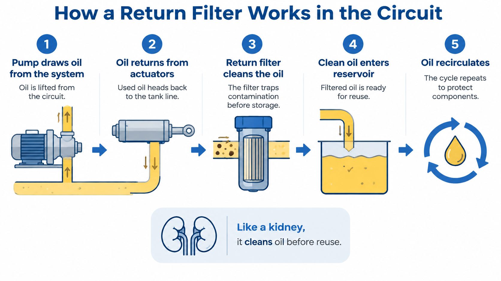
A return filter behaves like a kidney. It doesn't manufacture the fluid; it cleans whatever passes so the same fluid can be reused without carrying yesterday's wear into the pump. Stop the cleaning and the machine doesn't fail immediately. It gets dirtier until clearances open up and cycle times stretch.
The Five Stages
- The pump draws from the reservoir. It takes whatever the tank holds, clean or not, and pushes it into the pressure side. Nothing between tank and pump removes fine particles except, on some designs, a coarse suction strainer.
- Valves direct the flow. Directional, flow control and relief valves decide where the oil goes and at what pressure. Their spools and clearances are the first parts to suffer when the oil carries abrasives.
- Actuators do the work and hand the oil back. Cylinders and motors return oil carrying wear debris from rod seals, bore surfaces and motor internals, plus dust pulled in from outside.
- The return filter removes those particles. Sitting downstream of the valves and actuators, it catches contamination where it's generated, before the oil drops into the tank and gets drawn back into the pump.
- Bypass keeps the machine moving when the element loads. A restricted element raises back pressure, the bypass opens to protect the return line, and the machine carries on with unfiltered oil. The reservoir then becomes the dirtiest place in the system.
The reservoir is the one component nobody filters. Whatever arrives in it gets drawn out again, so tank cleanliness is decided at stage four. That's why a correctly specified return element does more for pump life than almost any other consumable on the machine.
A bypass that opens during normal running isn't protecting anything. It's telling you the element, the flow rating or the oil viscosity is wrong.
Trace the loop once on your own machine. Start at the pump outlet, follow the pressure line to the valve block and the actuators, then follow the return line back through the filter head to the tank. Mark where the bypass sits and where the indicator or gauge port is. That layout is what you'll be looking at when a reading starts climbing.
Return Filter Types and Where Each One Fits
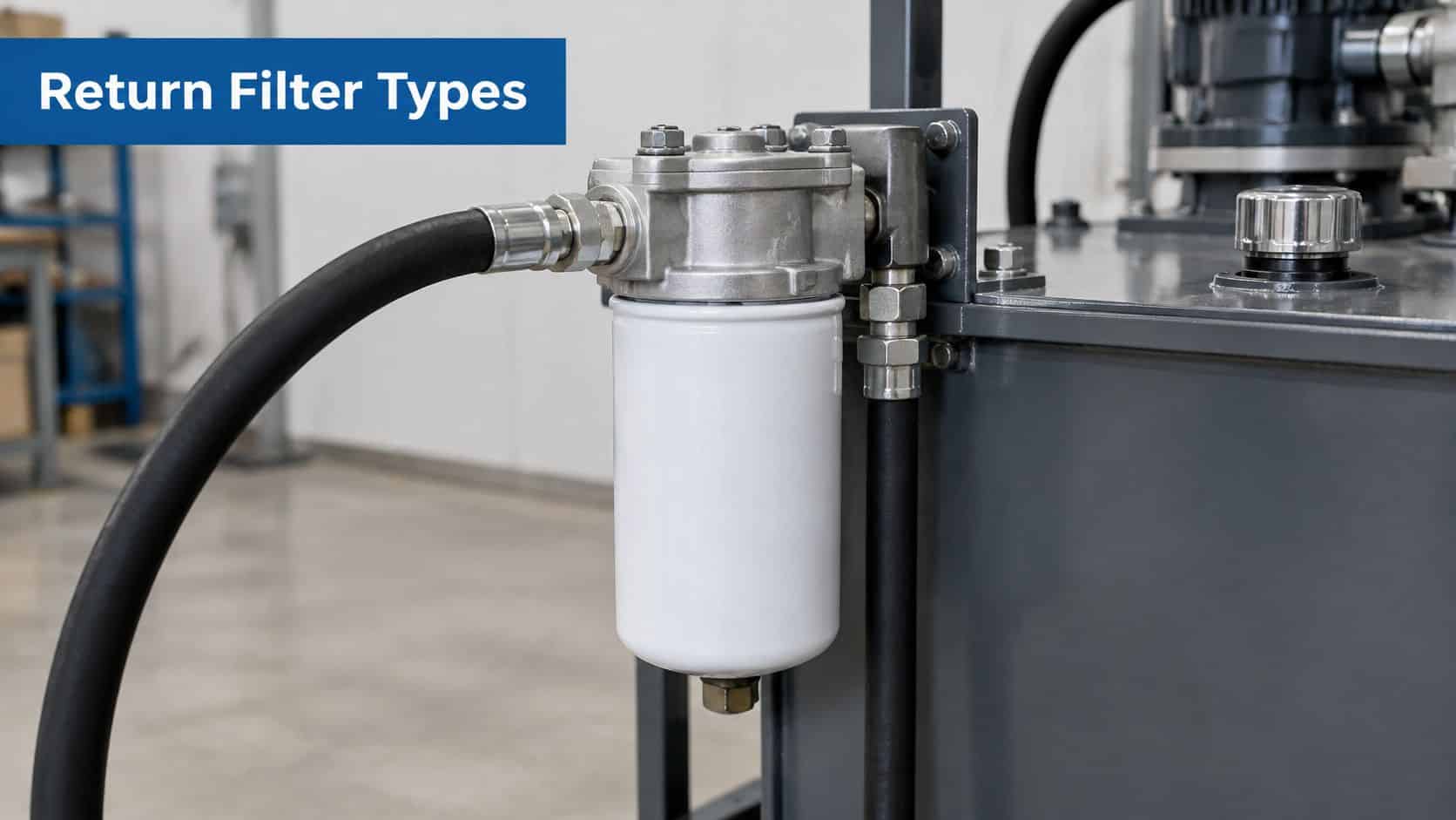
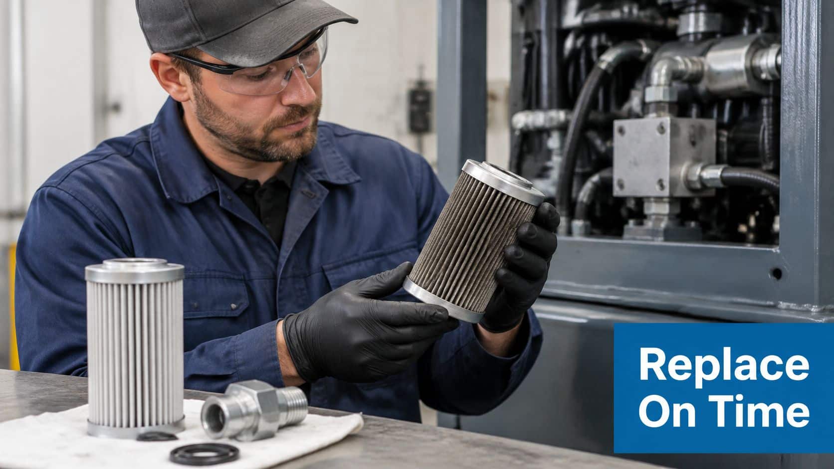
Placement decides what a filter protects, how fine it can be and how much pressure its housing has to survive. The unit pictured here is the arrangement most engineers meet first, a return element mounted on the tank line of an industrial power unit.
Return filter types and their main trade-offs
| Type | Location | Typical use | Main trade-off |
|---|---|---|---|
| Return-line spin-on | Return line before the tank | Most mobile and industrial circuits | Bypass opens if restricted; easy element change |
| In-tank return | Inside the reservoir | Compact systems with limited space | Needs tank access and draining for element change |
| Offline kidney loop | Separate pump and filter loop | Cleaning contaminated reservoir oil | Extra pump and space; separate from main circuit |
| Suction strainer | Pump suction line | Protecting the pump inlet | Coarse; not a return filter |
| Pressure-line filter | Pressure line before valves | Protecting sensitive proportional or servo valves | Higher pressure rating; sits on the pressure side |
Matching the Type to the Machine
The return-line spin-on is the default on mobile plant and smaller power units, and deservedly so. Element and canister come off as one piece, a change takes minutes, and the housing never sees system pressure. The cost is a disposable canister and a lower pressure ceiling, which matters only if someone fits one in the wrong place.
In-tank return filters sit submerged in the reservoir, saving external space on compact machines and often quietening return flow. The price appears at service time: tank access, a clean working area and usually a drain-down before the element comes out. Machinery serviced in a muddy field is the wrong place for one.
An offline kidney loop runs its own small pump and element, pulling oil from the tank and returning it filtered while the machine is idle. It supplements the return filter and is the practical way to clean a reservoir that is already contaminated. It needs space, a power source and a justification, so it earns its keep on large reservoirs and dirty systems.
A suction strainer guards the pump inlet against large debris and nothing else. It has to be coarse, because a fine element on the suction side starves the pump and causes cavitation, which wrecks it faster than the particles would. Treat it as a last line of defence rather than a substitute for return filtration.
A pressure-line filter sits downstream of the pump and protects proportional or servo valves, so it carries a full-pressure housing and a fine element. It is the right answer for contamination-sensitive control, and it costs what that answer costs.
Where the element lives decides how the service is done. The walkthrough below shows where the element sits and how it is changed, so watch it before a first change on unfamiliar equipment.
Whichever type you fit, judge it by evidence gathered after installation. Take repeatable oil samples from the same point each time and log the differential-pressure trend across the element: a falling particle count with a bypass that stays shut is a filter doing its job. A finer element that spends its life in bypass delivers worse reliability than a coarser one filtering continuously, because unfiltered oil reaches the tank every time the bypass lifts. Specifying the right position and type is only half the work; the trend data confirms whether the choice holds up in service.
Choosing Micron Rating, Flow and Bypass Settings
A micron rating is a claim. A beta ratio is evidence. Most catalogue entries give you the first and leave you to ask for the second.
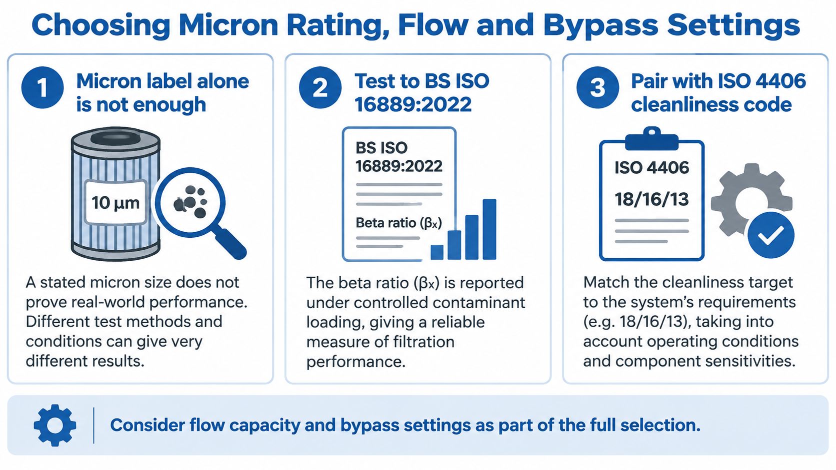
For UK procurement, ask for the element tested to BS ISO 16889:2022, the British adoption of ISO 16889, which reports the beta ratio under controlled contaminant loading rather than in a clean single pass (UFI hydraulic filter specifications). Pair it with a cleanliness target in ISO 4406 codes, which count particles larger than 4, 6 and 14 µm(c). Visual clarity can't establish compliance: oil that looks perfectly clean will still fail a 16/14/11 target. A commonly cited baseline for general hydraulic circuits is ISO 4406 19/17/14, while contamination-sensitive proportional or servo systems may need approximately 16/14/11. Our ISO cleanliness code guide explains what the three numbers mean when you're writing a sampling spec.
Six Checks Before You Specify
- Identify the least tolerant component. A proportional or servo valve sets the target; anything finer than that target is money spent on the wrong problem, anything coarser is a warranty claim waiting to happen.
- Confirm peak return flow in L/min. Not pump delivery. A differential cylinder returns considerably more oil on retraction than the pump supplies, and an accumulator discharging in bursts does the same thing in a shorter window.
- Check the viscosity range at the coldest start. Pressure drop rises as oil thickens, and the worst case is a cold machine in a January yard, not a warm test bay.
- Confirm the bypass setting against the OEM specification. A bypass set too low turns every cold start into an unfiltered circulation event.
- Check dirt-holding capacity against expected loading. A small element in a dusty environment loads in weeks and gets changed late because nobody is watching the indicator.
- Confirm the housing rating against maximum return-line pressure. Return lines aren't always low pressure once check valves, surge and shared tank lines are in the picture.
The trade-off that catches people is efficiency against pressure drop. Choosing the finest element available raises restriction, and restriction is what opens the bypass. On a machine with a cold-start duty cycle, the smaller advertised rating can deliver dirtier oil to the reservoir than a slightly coarser element that stays in circuit all day.
Practical rule: specify the element against the bypass setting, not against the finest number in the catalogue.
When you order, put it in one line: element format and micron rating, beta ratio stated at that rating, rated for peak return flow at the coldest working viscosity, bypass at the OEM setting, and the ISO 4406 target the circuit is meant to hold. That sentence removes most of the guesswork at the counter.
Replacement Intervals and Installation Practice
About 50 operating hours for the first change on new or rebuilt equipment, then 250 to 500 hours or six months, is the schedule most UK maintenance guidance quotes, and it's a starting point rather than a limit (servicing guidance for hydraulic filters). The same guidance is clear that a return filter should be sized around the circuit's maximum return flow rather than pump delivery, because actuator regeneration, differential-cylinder areas and intermittent accumulator discharge all create short-duration peaks.
The Three Signals Worth Trending
Differential pressure is the only signal that reports on the element itself. A rising reading means loading, and a reading that climbs within days of a change means something is shedding debris into the oil.
Oil temperature changes viscosity, and viscosity changes pressure drop. A machine that sits comfortably at 50 °C and trips the indicator on a cold start has a viscosity problem, not a dirt problem.
Particle counts tell you whether the filtration is working at all. Sample from the same point, on a warm machine, after the same amount of running each time, otherwise you're measuring your own sampling method.
One clean sample proves nothing. Three samples taken the same way tell you whether the element, the bypass or an ingress point is the problem.
Fitting the Element Correctly
- Clean around the housing before opening anything, so the debris on the outside doesn't become the debris on the inside.
- Transfer the new oil through clean equipment. Oil straight from the drum isn't automatically clean enough for a sensitive circuit.
- Fit new seals, lubricate them with the system oil, and check the flow arrow on the housing matches the return direction.
- Fill and bleed air from the housing before start-up, then run and check every joint for weeps.
- Reset the differential-pressure indicator after the change and log the operating hours, so the next decision has a datum.
Set three numbers before the first sample: where you sample (a live port downstream of the return filter, or the reservoir sampling valve), the baseline target (the ISO code from the specification table), and the alarm threshold, usually where differential pressure approaches the bypass setting or the particle count moves a full code above target. If a reading jumps early, work through the causes in the troubleshooting section before fitting another element. Our guide to changing a hydraulic filter covers the handling side in more detail. After that first sample you have a decision to make: hold the interval, shorten it, or chase a debris source. That decision, not the calendar, should set your service schedule.
Troubleshooting Return Filter Symptoms and Causes
The most common complaint isn't a burst element. It's an indicator that climbs within days of a change, or never resets at all, and the usual response is to fit another element and hope.
Return filter symptoms, likely causes and fixes
| Symptom | Likely cause | First action |
|---|---|---|
| Differential-pressure indicator rising quickly | Element loading or debris from a recent repair | Check operating hours, sample the oil and look for a pump or seal source |
| Bypass indicator open on cold start | Viscous oil raising pressure drop | Warm the system and check the bypass setting against the OEM specification |
| Oil still dirty after a new element | Ingress downstream of the filter or dirty incoming oil | Pre-filter new oil and check breathers and rod wipers |
| Foam or aerated oil in the reservoir | Air entering the return side | Check return-line joints and reservoir level |
| Milky or cloudy oil | Water ingress or condensation | Check breathers and seals, then drain and treat the water source |
| Particle counts high after several changes | Tramp oil or contamination the filter cannot remove | Fit an offline filter, skimmer or vacuum system and repeat sampling |
Where a Return Filter Stops Helping
Fluid quality is a broader control problem than any single element can solve. HSE guidance on maintaining hydraulic systems treats contamination as something that arrives through oil transfer, reservoir openings, seals and maintenance activity, and notes that tramp oil may need mechanical skimmers, coalescers or vacuum systems rather than ordinary particle filtration.
A return-line element only treats fluid while the machine is running. It can be bypassed on a cold start or under restriction, and it can't reliably remove water, dissolved contamination, varnish precursors or particles introduced after it. Knowing that boundary is what separates a maintenance plan from a filter-changing habit.
Field rule: fix the ingress before you fit another element, or the new one will load in exactly the same number of hours.
When contamination persists, the sequence that works is: pre-filter delivered oil before it goes in the tank, inspect breathers and rod wipers for the entry point, and move to offline filtration or fluid analysis when the reservoir itself is the source. Agricultural and mobile equipment exposed to rain, dust and irregular servicing is where this pays off fastest. And if the element is loading quickly while the oil tests clean, revisit the pressure-drop trade-off in the selection section. A finer element that trips bypass is worse than a coarser one that stays in circuit.
Confirm Your Return Filter Choice Before You Order
A clean order starts with six details: machine make and model, current element part number, maximum return flow in L/min, operating viscosity range, bypass setting and the cleanliness target in ISO 4406 codes. With those, a supplier can confirm the element and cross-reference alternatives instead of guessing from a photograph.
Before you commit, decide how you will prove the choice was right. Take a baseline differential-pressure reading at stable flow and temperature, trend it at each service, and pull oil samples from the same point under the same conditions. If ΔP climbs toward bypass while samples stay dirty, the element is too fine or the circuit needs attention upstream; if samples clean up and ΔP stays stable, the specification is doing its job.
A hydraulic filter cross-reference against the original part number is usually quicker than working from a description, particularly on older imported machinery where that number has been superseded. MA Hydraulics Ltd supplies hydraulic filters and the OMT range of filters, bellhousings and couplings, and can source from most major manufacturers when the original part is obsolete or hard to find. Call 01724 279508 or email info@mahydraulics.co.uk with the specification, then check the element against the table in Return Filter Specifications at a Glance and set the first service interval from the first sample rather than the calendar. See the wider range at MA Hydraulics Ltd.
