You've got a machine running, the alarm has just gone quiet, and someone is already blaming the pump. In reality, the problem often started much earlier, with dirty oil, poor sampling, or a cleanliness target that was never written down properly. The ISO cleanliness code gives you a practical way to control that risk before it turns into a strip-down, a parts order, and another lost shift.
For hydraulics, cleanliness isn't a nice-to-have. It's part of how you protect clearances, preserve valve response, and keep pumps alive for longer. If you want a broader maintenance reference point outside hydraulics, the maintenance and modernization of hydraulic elevators resource from Crane Elevator Company is a useful reminder that fluid condition affects reliability across similar lifting and power systems too.
Why Ignoring Fluid Cleanliness Costs You Dearly
A technician changes a failed pump, tops up the reservoir, and sends the plant back into service. A week later, the same circuit starts whining, the valves feel sluggish, and the new pump is already showing the same damage pattern. That's the usual shape of a contamination problem, the failure is rarely isolated, because the dirt that killed the first component is still in the system.
Hydraulic fluid cleanliness matters because solid contamination becomes an internal abrasive load. Once particles circulate through pumps, valves, manifolds, and motors, they score surfaces, disturb clearances, and shorten service life. In a mobile plant or an industrial power pack, that means the repair bill is only part of the cost, lost production and repeated intervention are usually the bigger hit.
Why the code matters in the workshop
The ISO cleanliness code turns a hidden problem into a measurable one. Instead of saying the oil looks dirty, you can write down a code, compare it with the target, and decide whether to run, filter, or flush. That shift matters because technicians need a common language, not a guess based on colour or smell.
The most useful habit is simple. Check the code, compare it with the component requirement, and act before wear spreads. That's especially important on mixed systems where a durable pump can survive longer than a sensitive valve stack, but the whole circuit still suffers if the oil is allowed to drift.
Practical rule: if a machine keeps failing after a component replacement, look at cleanliness history before you blame the replacement part.
Decoding the ISO 4406 Cleanliness Code
A machine comes back from a service, the oil looks acceptable, and the next sample still shows the same wear pattern. That is usually the point where the ISO 4406 code earns its keep. It gives you a particle-count result you can compare against a target, rather than relying on the colour of the oil or a guess from the sump.
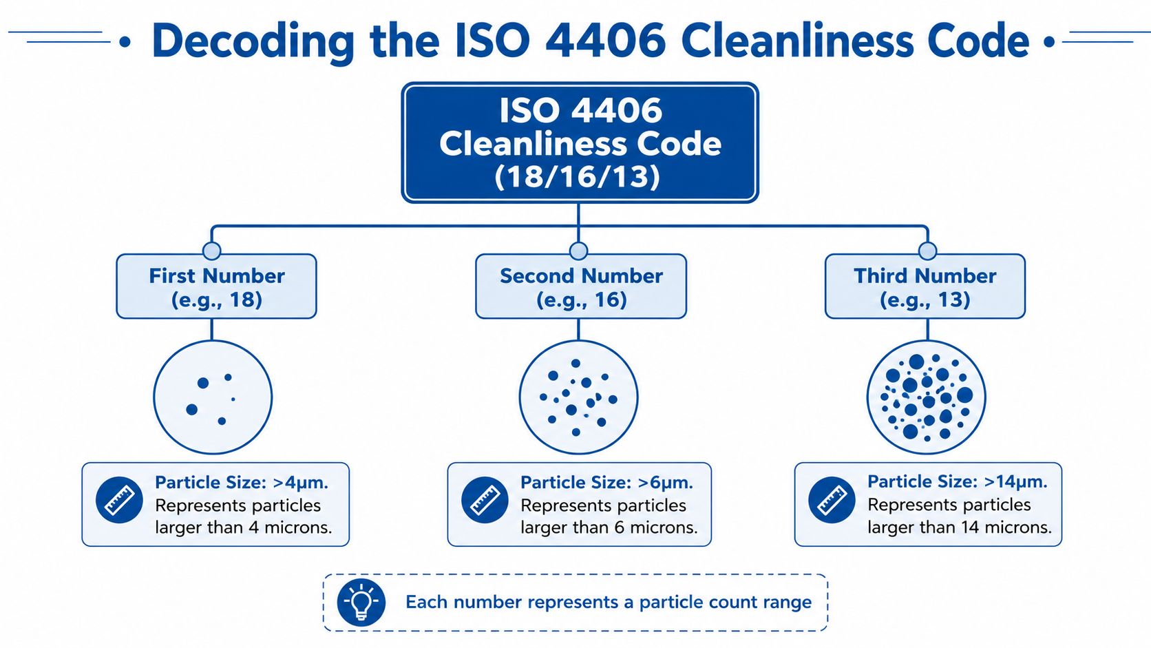
The code uses three numbers, so a reading such as 18/17/13 describes contamination across three particle size bands, particles >4 µm, >6 µm, and >14 µm. The idea is simple enough. Each band is reported separately, so you can see where the contamination sits instead of treating all dirt as the same problem ISO cleanliness code guidance.
How to read the numbers
Read the code as three separate results from the same sample. The first figure covers the smallest band, the second covers the middle band, and the third covers the larger particles. A higher number means more particles in that size band, so 18/16/13 is dirtier than 17/15/12.
The scale is logarithmic, not linear, and that changes how you judge a sample. One step on the code represents roughly a doubling of particle concentration BS ISO 4406:2021 overview. A code that only looks one step worse on paper can still mean a much higher abrasive load in the circuit.
For a practical reading of the numbers, a code of 15/14/12 corresponds to 160–320 particles per mL above 4 µm, 80–160 per mL above 6 µm, and 20–40 per mL above 14 µm. That is why the code belongs on a maintenance sheet, not just in a lab report. It tells you how much contamination is present, and it tells you whether the sample is moving in the wrong direction.
Why the logarithmic scale changes decisions
Once you work with the doubling effect, the target becomes more than a label. A one-step drift can mean a real change in wear rate, valve response, and seal life. On a mixed system, that matters because a gear pump may keep running while a proportional valve starts to suffer long before the pump gives an obvious warning.
The practical job is to write a cleanliness target into the spec sheet, then use it in the maintenance plan. For mixed-component systems, the target should reflect the most sensitive component in the circuit, not the least sensitive one. The published hydraulic fluid cleanliness standards used in UK practice are a useful reference point when you are turning a lab result into an action on the plant floor.
A technician does not need theory for its own sake. They need a code they can compare, a limit they can understand, and a decision they can act on before contamination turns into repeated component failure.
Recommended Target Cleanliness Levels for Components
A power pack with a gear pump, a directional valve, and one proportional valve does not get a sensible cleanliness target from a generic “clean oil” label. Start with the most sensitive component and work back from there. In UK practice, the target has to protect the tightest clearances in the circuit, because that part will show wear first and will usually drive the reliability problem long before the rest of the system complains. The hydraulic component benchmark levels used in ISO guidance show the spread clearly, with gear pumps around 19/17/15, piston pumps around 17/15/13, and servo valves around 16/14/11. That difference is the practical trade-off. Tighter clearances need cleaner fluid, and mixed systems should be written around the most sensitive item, not the easiest one to satisfy.
Typical target codes by component
| Component Type | System Pressure < 140 bar (<2000 psi) | System Pressure > 140 bar (>2000 psi) |
|---|---|---|
| Gear pump | 19/17/15 | 18/16/13 |
| Piston pump | 17/15/13 | 16/14/11 |
| Servo valve | 16/14/11 | 15/13/10 |
Use the table as a starting point, then check the actual duty. A machine that spends its life in harsher service, or runs at higher pressure, often needs a tighter target than the basic figure suggests. Severe operation above 3000 psi may justify tightening the target by one ISO code level across all three particle-size bands. That is the kind of judgment a maintenance engineer has to make. Pressure does not change the cleanliness requirement in isolation, but it raises the wear risk and shortens the margin for error.
How to use component targets properly
A gear pump can survive dirt better than a servo valve, but that does not mean the gear pump's figure belongs on the specification sheet. The circuit target follows the most sensitive component. If the system includes a servo valve, that valve sets the limit for the whole package.
Engineering habit: write the target against the most sensitive component first, then check whether pressure or duty cycle justifies tightening it further.
That habit matters during commissioning and when you are reviewing an older machine. A supplier may hand over a broad “acceptable cleanliness” note, but the component mix and pressure regime decide whether that note is fit for purpose. A relaxed target may keep a simple pump set running without trouble, while the same target can leave a proportional or servo-controlled circuit exposed to premature wear, sluggish response, and avoidable downtime.
Setting the Right Cleanliness Target for Your System
Mixed systems cause most of the confusion. A power pack may run a gear pump, feed a directional valve, and still include one proportional valve that is far less tolerant than the rest of the circuit. The target should follow the most sensitive component in the circuit, not the average one.
A practical way to set it is to start with the component mix, then work back from the weakest link. If the system includes a proportional valve or servo valve, that valve usually drives the cleanliness target for the whole machine. Gear pumps may tolerate more contamination, but their tolerance does not justify a looser spec if the rest of the circuit needs cleaner oil. In practice, the spec sheet should reflect the part that will suffer first, because that is the part that controls reliability.
A simple decision framework
List every component that sees the fluid. Include pumps, proportional valves, servo valves, motors, manifolds, and any item with tight internal clearances. Then identify the most sensitive item, because that is the part contamination will hurt first.
From there, set the system target to protect that item, and make sure every support process can meet the same standard.
- List the critical parts: include pumps, proportional valves, servo valves, motors, manifolds, and any component with tight internal clearances.
- Find the most sensitive item: if one valve is much cleaner-duty than the others, that part sets the target.
- Match the support equipment: transfer carts, drum pumps, and top-up kits should all be able to reach the same target.
- Write the target into the plan: put the ISO code on the spec sheet, the commissioning checklist, and the maintenance route.
That last point is where many systems slip. Cleanliness gets discussed during design or commissioning, then it never makes it into the documents the workshop utilizes. If the ISO code is not written into the spec, the maintenance team will fall back on habit, and habit is rarely consistent enough for a mixed hydraulic circuit.
What happens when the rule is ignored
If a mixed circuit is allowed to run to a target that suits only the stronger components, the sensitive parts become the first wear point. The symptoms often start with stick-slip, poor response, or erratic motion, long before a hard failure appears. By the time the problem is obvious, contamination has usually spread through the rest of the circuit as well.
The value of particle counting is in matching the result to the correct target. Count the particles, compare the result with the strictest component requirement, and make the decision from there. That is the difference between a cleanliness reading that looks acceptable and a target that actually protects the machine.
How to Measure and Sample Hydraulic Fluid Correctly
A cleanliness code only helps if the sample reflects what is happening in the circuit. Pull a poor sample from a dirty bung or a stagnant reservoir and you may end up servicing the machine for the wrong fault. The sampling point matters just as much as the analyser.

The British Standards inspection framework for hydraulic components requires the inspection document to state both the cleanliness requirement and the inspection method used, and it applies to particulate contamination on the wetted surfaces and volumes of components BSI inspection framework. That matters because cleanliness control is not limited to finished oil samples, it also covers parts and assemblies entering the system.
What good sampling looks like
Sample from a live, circulating system wherever possible. A running circuit shows you what the components are seeing. Reservoir-only sampling can mislead you if dirt has settled out or if the pickup point sits in a quiet zone.
Use a clean bottle, flush the sample point first, and keep the cap on until the last moment. Do not wipe the port with a rag that sheds lint, and do not sample from a container that has been left open on the bench. Those habits add contamination that has nothing to do with the machine.
Consistency matters more than fancy kit. Sample the same way every time, from the same point, under the same operating condition. That gives you a trend you can trust and makes it easier to decide whether a change in the iso cleanliness code is real or just a sampling error.
A good sample tells you about the system. A bad one only tells you how the bottle was handled.
Once you have a reliable result, use particle counting to compare it with the target written for the machine. That is what turns a number on a report into a maintenance decision. If the port, bottle, or handling is poor, the reading is noise and the code will lead you in the wrong direction.
The video reinforces the sampling workflow, but the discipline stays the same. Good documentation, clean handling, and a consistent test method stop you chasing false alarms and unnecessary fluid changes.
Achieving and Maintaining Your Target Cleanliness
A machine that meets its iso cleanliness code on paper can still drift out of spec in service. The usual causes are plain enough, poor handling, weak breathers, dirty top-up oil, and filtration that is not matched to the system's duty. If any one of those is neglected, the particles come back and the component life follows them down.
What to control first
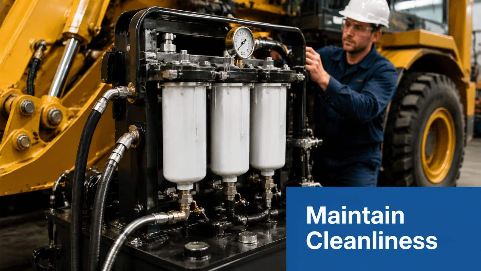
Start with the sources that feed dirt into the circuit. Good pressure and return line filtration remove what is already circulating, while offline filtration helps when a system needs a deeper clean-up between service intervals. Sealed reservoirs and proper breathers matter as well, because every tank breathes, and the intake air can carry dust and moisture straight into the oil.
That is why contamination control has to sit beside the filter spec, not behind it. A lot of maintenance plans focus on the cartridge and leave the fill point, the drum handling, and the breather arrangement untouched. That is a poor trade-off, because those small weak points often decide whether the oil stays clean or drifts back up again.
The ISO 4406 code, by itself, does not identify water, air, or oxidation by-products ISO 4406 limitations. A system can look acceptable by particle count and still give trouble because the oil has absorbed moisture or lost some of its protective properties. In practice, that means particle counting works best alongside tests for water content and viscosity.
Build a fuller picture of oil health
Particle counting tells you how many solid particles are in the fluid. It does not tell you where they came from, and it does not tell you whether the oil has taken on moisture or started to lose its protective film. If you chase the ISO code alone, you can miss the fault that is wearing the machine out.
The cleaner approach is to treat oil analysis as part of the maintenance routine, not as a separate exercise. A maintenance contract that asks only for a particle count can leave actual service conditions hidden, especially where a power pack has a mix of gear pumps and proportional valves with different sensitivity to dirt. If a system keeps drifting away from its target, the fix may be in the breathers, the transfer kit, the topping-up process, or the storage and handling of new oil rather than in the main filter element.
For a practical equipment-focused approach, MA Hydraulics also discusses contamination control in a way that fits day-to-day hydraulic maintenance. It is a useful companion topic when you are trying to keep dirty oil out of the circuit from the outset.
Your Hydraulic Cleanliness Action Plan
Start with the component that least tolerates dirt. Write its target ISO code onto the spec sheet, the commissioning checklist, and the maintenance route, then make sure every transfer and sampling tool can support that target. After that, sample from a consistent live point, trend the results, and don't treat one clean report as proof that the system is healthy forever.
If you're building a maintenance plan from scratch, the easiest way to keep it practical is to break it into clear actions, much like the guide to action planning for teams suggests for other technical workstreams. In hydraulics, that means one owner for sampling, one owner for filtration, and one owner for trend review, so the work doesn't disappear between shifts.
A workable checklist is straightforward. Identify the most sensitive component, set the system target from that requirement, sample the fluid correctly, and use filtration and breather control to hold the result. Then add water and viscosity testing so you're not blind to failures the ISO code can't see.
MA Hydraulics Ltd can support that process with component selection, filtration advice, and bespoke power pack builds that are specified around cleanliness from the start. If you want help turning an ISO target into a real maintenance plan or a cleaner system design, phone 01724 279508 today, or send us a message at MA Hydraulics contact page.
A CTA for MA Hydraulics Ltd.