
You've fitted the replacement valve, the connector looks familiar, and the machine needs to return to service. Before you reconnect it, establish what happens when the command disappears. A coil that energises correctly can still leave a loaded actuator moving, a cylinder drifting or pressure trapped where someone expects it to be safe.
Knowing how to wire a hydraulic solenoid valve means matching the electrical supply and connector to the coil, then proving that the hydraulic circuit responds safely. Use the manufacturer's datasheet and machine schematic together. Neither wire colour nor a familiar-looking plug is enough.
Read the Coil Data Before You Connect Anything
A coil can match the connector and still be wrong for the circuit. Confirm the exact coil and connector combination against its nameplate and datasheet before choosing a supply or switching device.
Check the rated voltage, AC or DC supply type, and current draw or power rating first. These set the electrical requirements for the circuit. Cable selection also depends on the installed length and permissible voltage drop.
Coil data to confirm before wiring
| Item | Where to Find It | Why It Matters |
|---|---|---|
| Rated voltage and AC or DC type | Nameplate and datasheet | A mismatch can prevent operation or overheat the coil |
| Current draw or power rating | Datasheet | Determines the requirements for switching capacity and circuit protection |
| Connector type and pin assignment | Connector moulding and datasheet | Incorrect pin identification can prevent operation or create an unsafe state |
| LED, suppression diode or driver fitted | Coil body and datasheet | May make DC polarity critical |
| Protection class (IP rating) | Nameplate | Helps determine the enclosure and sealing needed for the operating environment |
| Fail position when de-energised | Datasheet and machine schematic | Shows what the valve does when its electrical command is lost |
| Hydraulic pressure and flow rating | Datasheet | Confirms the valve is suitable for the circuit |
Record the coil details and connector orientation on the job sheet. This is especially useful when a drawing shows the mating face rather than the wiring side.
Confirm the valve's spool function, pressure rating and flow capacity against the hydraulic circuit. A correct electrical connection cannot make an unsuitable valve safe for the machine.
Practical rule: Identify terminals from their markings and the manufacturer's drawing, never from wire colour alone.
A 24 V DC coil is not interchangeable with a 24 V AC coil. Follow the current UK wiring regulations (BS 7671), including suitable overcurrent protection, conductor sizing and voltage-drop checks. The manufacturer's datasheet governs the coil's electrical figures and connection details.
Wiring Arrangements for DC and AC Coils
For a conventional DC relay circuit, take fused positive to the relay contact, connect the switched output to the coil's designated supply terminal, and return the other terminal to the supply common. Keep the functional return conductor separate from protective bonding. Don't use the valve body as a substitute for the return wire.
A PLC output changes the switching arrangement. A sourcing output supplies positive to the load; a sinking output switches its return. Confirm the output type, channel rating and permitted inductive load before choosing the connection.
Coil wiring arrangements by type
| Arrangement | Supply and Switching | Polarity and Suppression | Usual Fault |
|---|---|---|---|
| 12 V or 24 V DC coil switched by relay | Fused DC positive to relay contact, relay output to one coil terminal, other terminal to 0 V | Check polarity if LED or diode fitted; fit flyback diode per datasheet | Relay contact rated below coil current, causing contact wear |
| 12 V or 24 V DC coil driven from PLC output | Protected supply and coil connected to suit the output; sourcing switches positive, sinking switches the return to 0 V | Match sourcing or sinking output type; confirm approved suppression | Output channel rated below coil current |
| AC coil switched directly | Fused supply at rated AC voltage, switch in line, neutral to other coil terminal where the supply provides a neutral | No coil polarity; confirm voltage and approved AC suppression | DC or wrong AC voltage overheats the coil |
| Coil with built-in LED and diode | Connect per printed terminal marking | Reversal stops the LED and may stop the coil or damage protection components | Connection made against the marking |
These 12 V and 24 V DC arrangements follow the coil-control principles described in the UK wiring guidance; the exact connector and output instructions still govern the installation.
An AC coil doesn't require DC polarity, but that doesn't make its connections arbitrary. Keep switching in the designated live conductor and use the manufacturer's specified suppression, not a DC flyback diode.
Use the machine schematic and our circuit design basics to check the complete command path. If the fitted coil label disagrees with the drawing, resolve that discrepancy before connecting anything.
How to Wire a Solenoid Coil Step by Step
Prepare a suitable multimeter, lock-off equipment, insulated hand tools, correctly sized terminals and the connector manufacturer's tightening instructions. Only a competent person should carry out the electrical work and controlled live measurements.
The HSE guidance on working safely with electrical equipment requires secure isolation against inadvertent re-energisation; machinery electrical design should also follow the applicable principles of BS EN 60204-1.
Make the installation safe
-
Isolate and lock off every energy source. Disconnect electrical power, secure hydraulic and pneumatic isolation, and mechanically support loads that could fall or move. Prove electrical isolation and bleed trapped hydraulic pressure before touching the valve or conductors.
-
Check the coil and connector against the job record. Confirm supply type, current, pin assignment and fail position before selecting cable cross-section and protection; an undersized conductor can leave insufficient voltage at the coil.
-
Fit the specified fuse or circuit breaker near the supply. Coordinate its rating and operating characteristics with the cable, coil demand and output device. Don't increase the fuse rating to conceal repeated trips.
-
Route the command through the designated relay or PLC output within the machine's safety-control architecture. Don't feed the coil directly from a permanent live supply or bypass an interlock to make it operate.
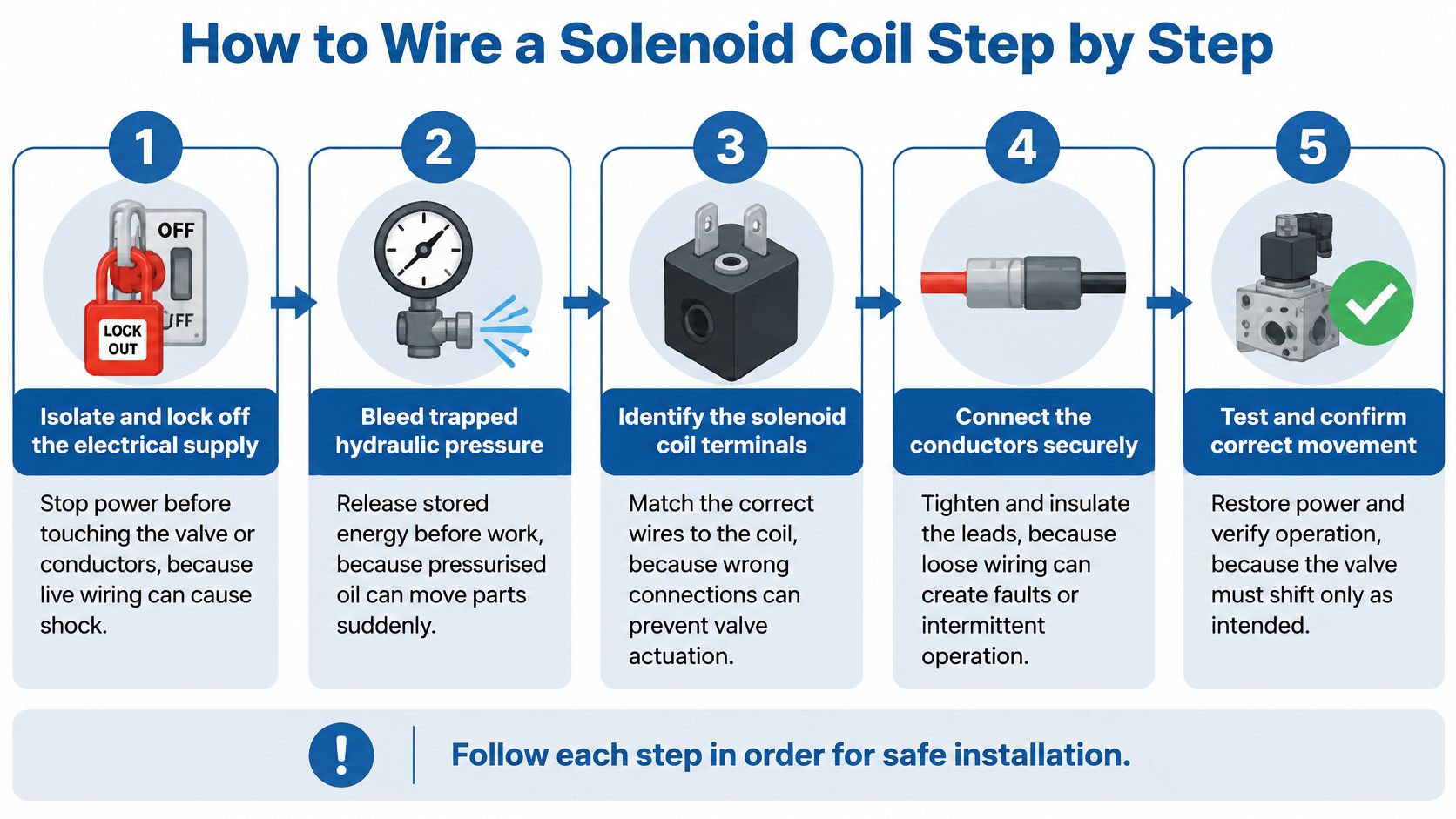
The process illustration provides a visual reminder of the isolation, connection and movement checks.
Connect and commission
-
Connect the correct return and verify polarity. Use the designated supply common or neutral, and follow the connector's printed markings where an LED, diode or driver is fitted. A reversed connector can damage suppression components rather than merely prevent operation.
-
Fit the manufacturer-specified flyback diode, suppression module or RC device where required. Check orientation and compatibility before energising; suppression selection can affect release behaviour, so don't substitute components without approval.
-
Seat the connector gasket, tighten terminals to the specified torque and secure the cable gland around the outer sheath. Provide strain relief and bond exposed conductive parts as the electrical design requires, keeping protective bonding distinct from the functional return.
-
Test before restoring normal operation. Measure resistance and perform the approved insulation checks with sensitive electronics disconnected as required, then commission with people clear and loads secured. Jog the valve under controlled conditions, verify movement and actuator direction, inspect for leaks, measure terminal voltage under load and record terminal numbers, wire colours and the de-energised state.
A successful energisation test proves only that the command can operate the valve. Acceptance also requires a safe response when that command disappears.
Safety Checks That Stop Unexpected Movement
A spring-centred valve isn't automatically safe. Its centre condition may trap pressure, unload a circuit or connect ports in a way that allows a loaded actuator to move. The correct outcome depends on the load, stored energy and the complete hydraulic arrangement.
The HSE machinery-safety guidance states that loss of electrical power to solenoids or loss of hydraulic pressure must not create a dangerous situation in safety-related machinery. It also supports appropriate valve monitoring and prevention of restart after a valve fault.
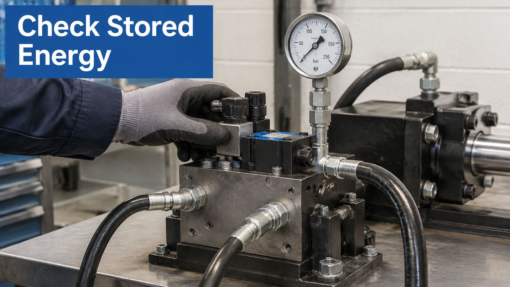
The valve, actuator and pressure indication must be considered together during commissioning.
Separate command from safety verification
An emergency-stop contact in series with the coil isn't, by itself, a complete safety function. Use the risk-assessed safety architecture, which may require a safety relay or safety PLC, monitored valves, controlled pressure dumping and independent load holding.
Coil current doesn't prove spool position. Where the safety function requires confirmation, monitor the relevant valve position or use an appropriately designed redundant arrangement. A deliberate reset must not itself command hazardous movement.
For teams reviewing responsibilities and hazard controls, Opus Safety's essential health and safety principles provide useful general context. Machine-specific validation still needs competent engineering assessment.
Validate every operating mode
Use a documented test plan, with hazardous faults simulated safely rather than created on an uncontrolled machine:
- Emergency stop: Record stopping behaviour and load retention.
- Power restoration: Confirm that movement doesn't restart automatically.
- Broken wire: Verify the response to loss of a command conductor.
- Failed coil: Check that loss of actuation produces the intended outcome.
- Stuck valve: Assess each hazardous spool position through an approved validation method.
- Pressure loss: Confirm that the actuator remains safe when hydraulic pressure disappears.
Provide an accessible, lockable local isolator and hydraulic shut-off and drain points. Maintenance must not depend solely on removing coil power.
Testing the Coil with a Multimeter
Test in separate stages: isolated resistance checks first, controlled live voltage checks second. Disconnect the coil before measuring resistance so parallel wiring and output electronics don't distort the result.
Compare readings with the manufacturer's specification at the stated temperature. A small coil and a larger coil needn't have similar resistance, and a continuity buzzer alone won't establish that a winding is healthy.
Multimeter readings for coil and supply checks
| Test | Meter Setting | Healthy Reading | Fault Indicated |
|---|---|---|---|
| Coil resistance | Ohms, coil disconnected | Within the datasheet value at the stated temperature | OL suggests a broken winding; unexpectedly low resistance suggests a winding fault |
| Supply voltage at coil, energised | DC or AC volts | Within the manufacturer’s stated tolerance | Low voltage from cable drop, poor connections or an undersized supply |
| Continuity from supply to coil terminal | Continuity or ohms, isolated conductor | Low resistance consistent with cable length | Open cable, loose terminal or failed fuse |
| Coil to earth | Ohms, power off and coil disconnected | Very high resistance, no unintended path to earth | Possible winding insulation failure |
| DC supply polarity | DC volts | Positive reading with the positive probe on the marked positive terminal | Reversed polarity can stop the LED or damage a diode |
| Coil temperature after running | Surface probe or thermometer | Within the manufacturer’s temperature limit | Excess temperature warrants checks for supply, duty or mechanical problems |
Measure where the load is connected
Measure voltage across the coil terminals while energised, using safe access and suitable probes. A correct reading at the power supply doesn't establish that the same voltage reaches the coil through the fuse, relay and harness.
For continuity testing, isolate both ends of the conductor where necessary to exclude alternative paths. Never select resistance mode on an energised circuit.
Testing caution: A multimeter earth check is only a screening test. It doesn't replace a specified insulation-resistance test.
Use an insulation tester only at a manufacturer-approved test voltage and with vulnerable electronics disconnected. Don't judge temperature by gripping the coil: permitted operating temperatures can be unsafe to touch. Record readings, operating conditions and measurement points as the known-good baseline.
Fixing a Valve That Will Not Shift
The coil clicks, but the actuator stays still. Don't order another coil until you've separated the electrical command from the hydraulic response: an energised winding doesn't prove that the spool moved or that oil can reach the actuator.
The HSE guidance on machinery control and maintenance highlights control-system failures and warns that pressurised hydraulic fluid can penetrate skin, causing injuries requiring major surgery or amputation. Isolate and release stored energy before unplugging connectors, opening hydraulic connections or checking mechanical freedom; live voltage measurements require a separate controlled procedure.
Symptoms, causes and first checks
| Symptom | Likely Cause | First Check |
|---|---|---|
| Coil clicks or hums but spool does not move | Blocked spool, contamination or pressure imbalance | With energy isolated, pressure released and loads secured, check spool freedom by the approved procedure |
| Coil stays cold and valve does nothing | No supply at coil, failed fuse or open winding | Controlled voltage check at energised coil, then isolated resistance test |
| Coil runs hot and fails early | Excess voltage or AC coil supplied with DC | Compare supply voltage and coil type against nameplate |
| Valve operates intermittently | Loose connector, poor return or failing relay contact | Isolate and reseat connector; then measure relay-contact voltage drop safely |
| Valve shifts but actuator drifts | Spool leakage, inadequate load holding or stored energy | Secure load and isolate pressure before inspecting load-holding components and leakage paths |
| LED does not light on DC coil | Reversed polarity or failed indicator | Isolate, verify markings and correct leads only where the datasheet requires |
| Valve does not reach safe state when power is removed | Wrong fail position or incorrect terminal connection | Compare fitted valve and wiring with schematic |
Fix the cause, not the symptom
Replace a failed fuse only with the specified rating and investigate why it opened. Check contamination, pressure imbalance, spool configuration and return-path restrictions before blaming the electrical supply.
Black Rhino Electric's electrical troubleshooting resource offers general fault-isolation context, but residential guidance doesn't establish machinery safety requirements. Use our hydraulic fault-finding techniques alongside the machine documentation.
If a correctly supplied coil fails, replace the approved failed component rather than attempting a winding repair in the field. Replace the complete valve where it isn't serviceable or its integrity is uncertain.
Sign Off the Wiring Before Power Up
Use a go/no-go record, not a verbal assurance. Authorise controlled commissioning only when the installation checks pass, then release the machine for service after functional safety validation.
- Identity: Coil voltage, AC/DC type and pinout match the documentation.
- Protection: Fuse or breaker and cable cross-section suit the circuit.
- Connections: Polarity, suppression, sealing and bonding are confirmed.
- Safety: Emergency-stop and restart behaviour pass the approved tests.
- Traceability: Fail position, terminal numbers, wire colours and readings are recorded.
Where formal authorisation applies, Safety Space's explanation of work permits helps distinguish permission to work from technical acceptance. Store the signed testing and commissioning record in the maintenance file; unresolved discrepancies mean the machine stays isolated.
We stock the full OMT Group inline circuit valve range, Hoyea Cetop directional and proportional solenoid valves, Cetop modular valves and a range of Orta valves. Have the coil details and machine schematic available when asking us to help select a replacement.
For valve selection and application advice, visit MA Hydraulics Ltd with your coil nameplate details, connector information and required fail position. Phone 01724 279508 today, or send us a message so we can help match the replacement components before the machine goes live.
