
One radiator's too hot to touch, the room at the end of the run never warms up, and on the machine next door one cylinder races ahead while its partner lags behind. You've already turned a valve twice, the noise changed, and the problem moved somewhere else. That familiar loop is exactly where good valve and balancing work starts, not with another quarter turn, but with a measurement.
Balancing means giving every branch the flow it was designed for, no more and no less. Once you understand why flow misbehaves, which valve does which job, and what to record before you adjust anything, the symptoms stop looking random. You'll also spot the trap that catches experienced teams, where restricting a valve hides a pump, pressure or contamination fault and raises energy use.
What Valve Balancing Does and Why It Matters
Think of a garden hose feeding several sprinklers on one line. The sprinkler nearest the tap soaks its patch, the middle one does fairly well, and the farthest one barely drips onto dry grass. The water isn't being awkward. It's taking the easiest route, and the near sprinkler offers the least resistance.
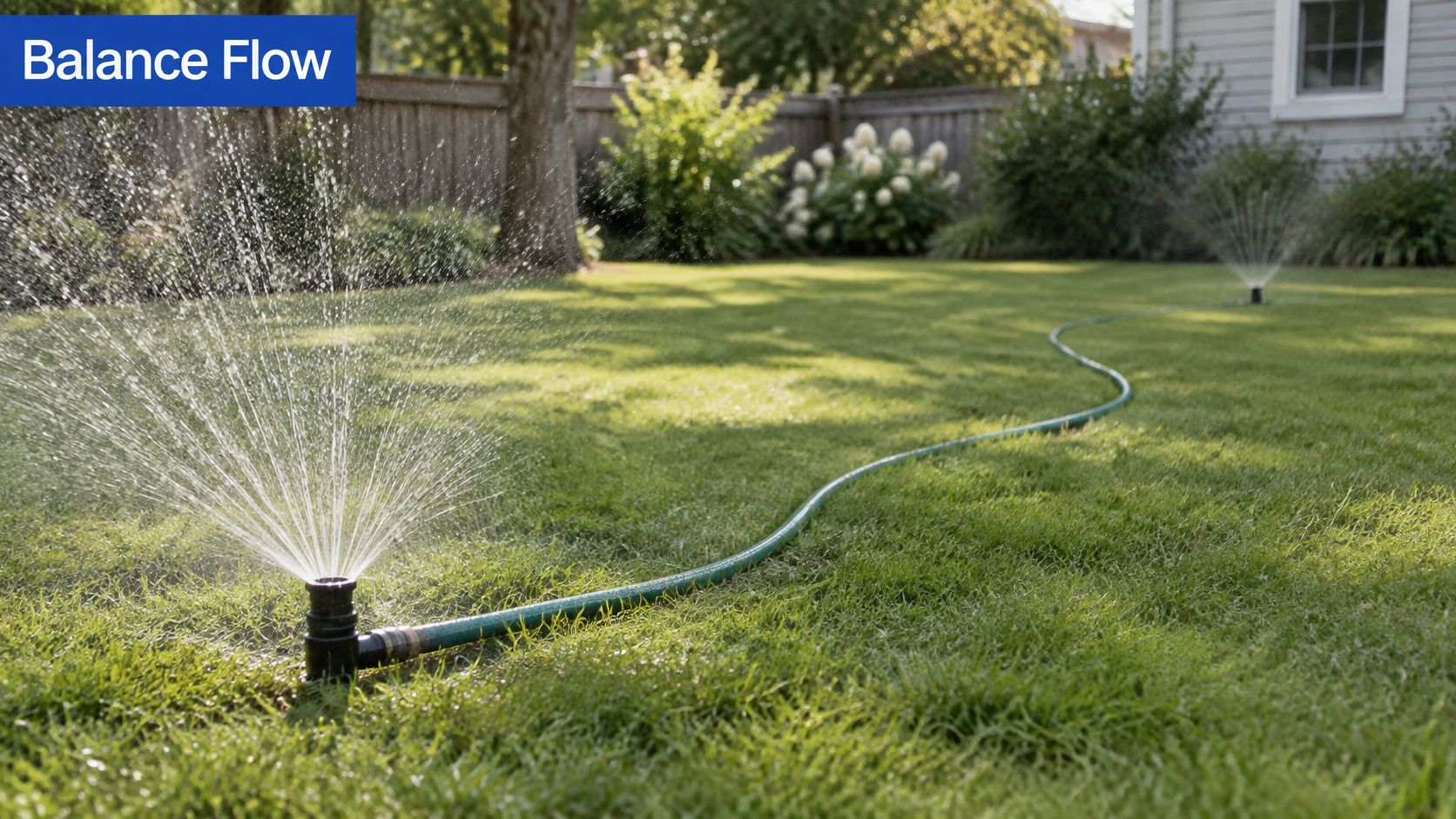
Your heating circuit or hydraulic machine works the same way. Flow follows the path of least resistance, so branches nearest the pump take more than their share until you deliberately add resistance to them. Balancing is that deliberate adjustment. You restrict the favoured branches just enough that every terminal unit, cylinder or motor receives its intended design flow, even when pump pressure changes.
Gardeners solve the same problem by grouping sprinklers with similar demands, and a useful overview of commercial sprinkler zone planning shows how splitting a system into zones stops one area stealing pressure from another. The scale differs, but the logic transfers directly to pipework and hydraulic branches.
Static and dynamic balancing
There are two families to keep straight. Static balancing sets a valve once to a fixed maximum flow. It suits steady systems where conditions rarely change. Dynamic balancing uses pressure-compensated devices that keep adjusting internally, so flow stays steady when other branches open, close or change load.
If conditions in your system keep changing, a valve set once and forgotten can't keep up. Something in the circuit has to respond for you.
Why this is commissioning work
UK practice has moved from fixed-flow systems toward variable-flow control, and industry reporting on hydronic balancing stated that more than 95% of new UK projects were designed with differential-pressure control valves protecting small terminal-unit circuits by around 2010, although those circuits still required proportional balancing between terminal units. UK building regulations require fixed building services to be commissioned through testing and adjustment, so balancing sits inside commissioning rather than being a casual tweak after installation.
Pressure-independent control valves go further by combining flow regulation with pressure compensation at each terminal unit. One warning is worth underlining. A variable-speed pump saves no energy if it's left running at constant speed, whatever the nameplate promises.
Apply one test to any system you're handed. At design load, does each room, machine function or actuator get the flow it was designed for? If you can't answer with readings, the system isn't balanced yet, however quiet it sounds.
Balancing Valve Types Compared Side by Side
Start with the overview, then read down the same list in order. Each device solves a different problem, and choosing the wrong type is the most common reason balancing never quite holds.
| Device | Main job | Adjustment | Typical use |
|---|---|---|---|
| Manual balancing valve | Sets a fixed maximum flow by adding controlled resistance | Manual, set on site with a flow meter | Hydronic heating and chilled water branches |
| Automatic flow limiter | Holds a set flow despite changes in pressure | Set once, fixed flow cartridge | Terminal units on variable-pressure circuits |
| Differential-pressure control valve | Holds a constant pressure difference across a branch | Pressure setpoint adjustment | Protecting small terminal-unit circuits |
| Pressure-independent control valve | Combines flow regulation with pressure compensation | Flow setting plus control signal | Fan coils, air handling units and radiators |
| Hydraulic flow control valve | Controls flow rate to an actuator in a hydraulic circuit | Adjusted orifice or setting | Mobile and industrial hydraulic machines |
| Flow divider | Splits flow between two or more actuators | Set by design, checked per group | Synchronised cylinders and motors |
The chart below shows the same families visually, with function, adjustment method and best use side by side.
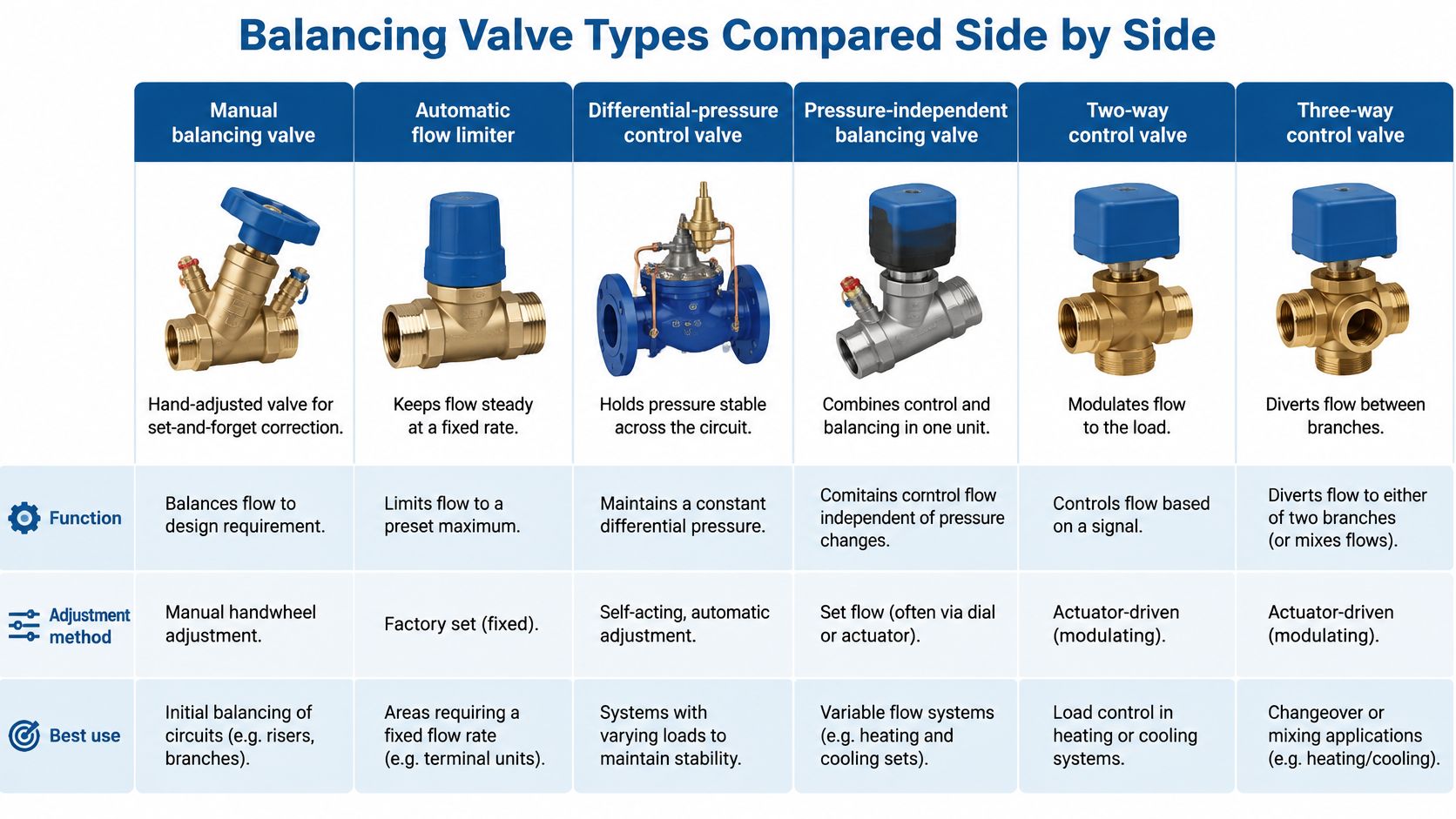
A manual balancing valve is the simplest option. You turn it, measure the flow, lock it, and it stays there. A double regulating valve adds a memory stop so it can be closed for maintenance and reopened to the same setting. Use these where load is steady.
An automatic flow limiter holds a fixed flow using an internal cartridge, even when pressure upstream wanders. A differential-pressure control valve works one level up, holding pressure difference steady across a whole branch so the valves inside that branch behave predictably.
A pressure-independent control valve combines both jobs in one body. You set the design flow, the valve compensates for pressure swings, and a control signal modulates delivery to the load. It's the tidy answer for fan coils and air handling units on busy variable-pressure circuits.
In hydraulic machinery, a hydraulic flow control valve meters oil to an actuator so a cylinder or motor runs at the right speed. A flow divider tackles a different problem. It splits one supply between two or more actuators so paired cylinders or motors move in step, which matters on lifting platforms and mobile plant.
This short video walks through how these valves behave in a working circuit, so watch it with the table in mind and match each device to its job.
Three questions that decide the choice
- Does supply pressure vary? If it does, favour automatic or pressure-independent devices over fixed manual settings.
- Does the load change during operation? Changing load needs a valve that responds, not one locked at commissioning.
- Must two or more actuators move in step? If yes, you're looking at a flow divider, not individual restrictions.
Balanced flow alone doesn't guarantee efficient control. The BEAMA summary of the University of Salford study reported that replacing a simple manual radiator valve with a thermostatic radiator valve could reduce heating energy use by approximately 20%, because the valve also responded to changing room temperature. Flow gets the water there. Responsiveness stops it overheating the room once it arrives.
Before ordering, confirm the design flow, the pressure range, the connection size in millimetres, and how you'll measure flow after fitting. If any answer is missing, you're not ready to order.
Measuring Flow and Pressure With the Right Units
You can't balance what you haven't measured, and you can't compare readings taken in mixed units. Keep one standard set, record it the same way every time, and the numbers start telling a story.
| Parameter | Metric unit | Typical instrument | When to record |
|---|---|---|---|
| Flow rate | litres per minute (L/min) | Flow meter or balancing meter at a measuring point | Before and after each adjustment, at design load |
| Pressure differential | bar or kPa | Differential pressure gauge or transducer | Across the valve, pump and each branch |
| Absolute pressure | bar | Pressure gauge with pulsation damper | Supply, return and relief setting checks |
| Temperature | degrees Celsius (°C) | Calibrated probe thermometer | Flow and return, or oil temperature in hydraulic circuits |
| Pump speed | revolutions per minute (rpm) | Tachometer | Whenever the drive is variable-speed |
| Fluid cleanliness | ISO cleanliness code | Particle counter or oil sample | Baseline at commissioning and after major faults |
Why metric is a compliance point
This isn't a house style preference. The UK Government guidance on units of measurement states that metric units must generally be used for trade purposes under the Weights and Measures Act 1985, with imperial figures shown only as supplementary information and never more prominently. So write millimetres, litres per minute, bar and degrees Celsius as your primary values on every sheet, label and report.
Consistent units also prevent silly errors. A flow noted without units, or converted in someone's head, is a fault waiting to happen. If you need to work out expected flow from pump data first, run through the flow rate calculations before you pick up a meter, so you know what a sensible reading looks like.
Reading habits that make numbers trustworthy
- Measure under representative load: An idling system gives flattering readings that collapse under real demand.
- Let temperatures stabilise: Cold oil is thicker and cold water circuits haven't settled, so early readings drift.
- Measure differential pressure directly: One gauge across a valve beats two absolute readings subtracted later, with half the error.
- Check gauge calibration: An uncalibrated gauge turns careful balancing into guesswork with extra paperwork.
Practical rule: If a reading surprises you, repeat it before you act on it. Surprises are often air in a tapping point or a gauge that hasn't settled.
A small maintenance team doesn't need a laboratory. Capture flow, pressure differential, temperature and a cleanliness code, logged against the design values for each branch. That minimum set lets you prove balance today and spot drift next year.
How to Balance a Hydraulic or Fluid Circuit Step by Step
Work through these eight steps in order. Skipping ahead is how people end up adjusting the same valve four times.
-
Gather the design data. You need the intended flow in litres per minute for each branch, the design pressure and the relief setting. Without a target figure, every adjustment is a guess, so get the numbers from the drawings or the machine manual first.
-
Check the circuit is clean and bled. Confirm filters and strainers are fitted and clean, then bleed air from high points. Air compresses and debris blocks orifices, and both give readings that wander while you watch them.
-
Open every balancing valve fully. Start from a known, unrestricted condition and run the pump at its normal operating speed. The common slip is starting from wherever the last person left the settings, which bakes their mistakes into yours.
-
Measure the pump, then each branch. Record pump outlet flow and pressure first, because that tells you whether the supply itself is healthy. Then measure each branch flow in turn and write every value down, however wrong it looks.
-
Start with the branch furthest from the pump. Close its valve gradually until flow matches design. That branch has the hardest job getting its share, so secure it first. Adjusting near branches first starves the far ones and forces you to start again.
-
Work back toward the pump, then recheck. Set each nearer branch to its design flow, knowing each change nudges the others. Loop round again until every branch sits within the agreed tolerance, commonly around 10% of design in a worked example. Patience here is the whole craft.
-
Lock and mark every setting. Use the valve's locking device or memory stop, then mark the position with a paint pen or tag. An unmarked valve will be "helpfully" adjusted by someone within a month.
-
Record before and after values. Log each branch flow, pressure differential and valve position alongside the original readings. That sheet becomes your baseline for every future fault, so file it where the next engineer will find it.
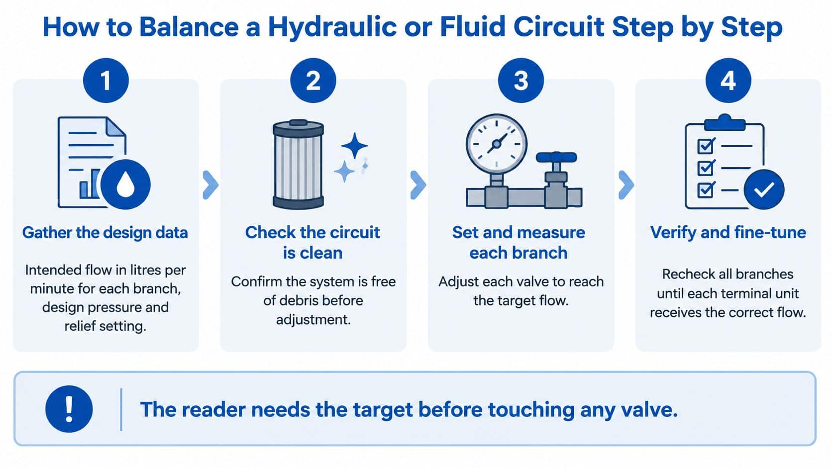
The process diagram below summarises the same sequence. Its four stages are design data, clean circuit check, branch setting and verification, matching steps 1 to 8 above.
What a balanced circuit looks like
Picture a three-branch circuit in words. The pump feeds a common header, each branch has its own balancing valve, and flow measuring points sit at the pump outlet and on each branch. Those four measuring points are exactly where steps 4, 5 and 6 take their readings.
- Pump outlet point: Confirms total flow and supply pressure before you touch a branch.
- Branch one, nearest the pump: Usually needs the most restriction.
- Branch two, middle distance: Set after the farthest branch is secure.
- Branch three, farthest away: Set first, rechecked last.
You're finished when every branch sits within tolerance, the pump runs at its design point, and adjusting one branch no longer changes flow in another. Balancing on a cold, unrepresentative load is the classic shortcut that undoes all of it, so always verify at working temperature and real demand.
Diagnosing Balancing Faults Before You Adjust Again
A branch runs cold while another overheats. The first instinct is often to turn a valve, but that can hide the underlying problem. Treat balancing as commissioning and diagnosis: measure flow and pressure before changing a setting, then check whether the readings support that change.
| Symptom | Likely cause | First fix |
|---|---|---|
| One branch runs cold while others overheat | An upstream branch is taking too much flow, starving the farther branch | Measure branch flows, then balance from the farthest branch toward the design flow |
| Valve noise or whistling | Excessive differential pressure across the valve | Measure the pressure difference, then check the balancing valve setting and pump setting |
| Flow falls over time | A blocked strainer or contaminated fluid | Inspect and clean or replace the strainer, assess the fluid, then recheck flow |
| Actuator drifts when held | Internal leakage or a worn valve spool | Test for leakage and replace seals or the spool as needed |
| System pressure is high at every point | The relief valve setting may be too high, or the pump may be running too fast | Compare the relief setting and pump speed with the design values |
| Valve adjustment does not change flow | The valve type may be wrong, or a bypass may be open | Confirm the valve type and check the circuit for an open bypass |
More balancing is not always better
A valve that is restricted further may quiet a symptom without correcting its cause. An oversized pump, excessive pressure, internal leakage or a control problem can all be masked by squeezing a branch. The system may appear fixed while using more energy.
Fixed building services are required to be energy-efficient, effectively controlled and commissioned through testing and adjustment. The UK building regulations link is to a commencement order, not the instrument that sets those requirements. The practical point remains: assess measured performance, not whether a balancing valve is present.
A valve wound nearly shut is a clue, not a cure. Find what it is compensating for before restricting it further.
Separating a balancing fault from everything else
Use a consistent diagnostic order. Check the setting first against the commissioning record, since a valve may have been knocked or changed. Check the readings next, comparing flow and pressure drop with the recorded baseline. Note the duty cycle too, so the comparison reflects how hard the circuit was working. Then check the fluid and other components. Contamination, pump wear, electrical control faults and actuator leakage can resemble a balancing fault but call for different repairs.
A measurement helps distinguish these causes. If flow is low and the pressure drop across a branch is also different from its baseline, the branch restriction or supply conditions may have changed. If flow does not respond when the valve setting changes, look for a bypass or a mismatch between the valve and the circuit. High pressure across the system points toward a pump or pressure-control issue, not a reason to keep tightening a branch valve.
Building hydronic circuits and industrial or mobile hydraulic circuits share balancing principles, but their components and procedures differ. Proportional and directional valves, flow dividers and pressure-compensated circuits do not behave like a basic heating branch. Apply the wrong circuit assumptions and an adjustment can make diagnosis harder.
Stop if the readings suggest a safety risk. Never raise a relief setting beyond the component rating to force flow, and do not continue restricting a noisy valve when pressure may be excessive. If measured values fail to respond as expected, or pressure remains high throughout the circuit after basic checks, have a specialist investigate with suitable test equipment rather than making further adjustments.
Commissioning and Maintenance Routines That Hold Balance
A circuit can leave commissioning in balance and drift as filters collect debris, pumps wear, seals age or settings are disturbed during repairs. The remedy is a repeatable routine: retain the original measurements, check them under comparable operating conditions, and investigate changes before turning a valve again.
A six-step routine that holds
- File the commissioning record. Keep design flows, measured values, valve positions and the commissioning date together. This record is the baseline for future checks.
- Repeat key readings after settling. Recheck once air has worked out and temperatures have cycled properly. The readings show whether the original settings still suit normal operation.
- Monitor on a fixed schedule. Track pressure, flow, oil temperature, contamination and pump vibration at planned intervals, not only after someone reports a problem.
- Trend against the baseline. One reading is a snapshot. Comparing readings over time can reveal gradual changes, such as a loading filter or a wearing pump, before they become more serious.
- Service filters and strainers on time. A clogged strainer changes the circuit's resistance and can upset its balance.
- Re-balance after component changes. Replacing a valve, pump or motor can alter branch resistance. Recheck the affected branches using this guide to testing and commissioning.
Keep the routine practical. Record what was measured, the operating conditions and any adjustment made. When a reading changes, compare it with the baseline before adjusting again. A restricted valve may be compensating for a pump, pressure or contamination problem. Continuing to restrict flow can conceal the fault and increase energy use, rather than restore proper operation. Planned maintenance is also familiar in settings such as air conditioner maintenance. Your hydraulic and hydronic circuits deserve the same treatment.
Sensors help, competence decides
The National Fluid Power Centre update describes training that covers monitoring pressure, flow, oil temperature, moisture, contamination, pump vibration and electrical performance, alongside predictive maintenance and root-cause analysis. Sensors can show that conditions have changed, but someone competent still needs to place them appropriately and interpret the readings.
Technicians must be able to diagnose valves, pumps and gearboxes and interpret circuit diagrams. Digital monitoring supports that work by making trends visible. It cannot compensate for poor sensor placement, missing baselines or weak fault interpretation.
Balance, verify and trend. Record intended values, measure actual values under load, and keep both so the next reading has meaning.
When readings drift, use the symptom table to diagnose the cause before rebalancing. Stable readings within tolerance, supported by a dated record of changes and reasons, show that the routine is holding.
Choose Balancing Components With Confidence
A valve that fits the connection may still be the wrong choice for the job. Start by confirming the design flow for each branch in litres per minute, then consider pressure variation, changing loads and whether actuators need to move together. These details guide valve selection and give you target values to check during commissioning.
Keep the measured results with the circuit drawings. A dated, branch-by-branch record of readings before and after adjustment makes later diagnosis easier. If a valve needs repeated adjustment, measure again before restricting the flow further. A restriction can mask a pump, pressure or contamination fault and increase energy use.
Component choice matters when a circuit has different duties. MA Hydraulics supplies Hoyea Cetop 3, Cetop 5, Cetop 7 and Cetop 8 valves, Hoyea modular valves, OMT Group valves, Oleoweb hydraulic valves and components, Taicin valves, ORTA manual and diverter valves, and Vivoil flow dividers. Its wider range includes pumps, valves, gearboxes, filters and power transmissions, motors, flow dividers, power packs, accessories and pressure switches.
Discuss the duty cycle and branch flows before ordering. MA Hydraulics can help with cross-references for hard-to-find parts, component selection and complete power pack assemblies. Send us a message to review your circuit and valve selection before you commit.
