
Pressure class and operating temperature are separate limits. BS EN 13828 covers building-water ball valves classified up to PN16 and sets a normal distribution temperature limit of 65°C. Check the standard's scope and requirements against the intended duty, then assess pressure, temperature, materials and approval together.
A valve may fit the pipe yet still be unsuitable for the installation. For engineers, maintenance teams and buyers, the useful test is whether the complete valve suits the system's worst operating conditions, not whether a supplier labels it low pressure. Low pressure is a rating, not a valve category: selection depends on the duty, seal material and applicable regulatory route.
Low Pressure Ratings at a Glance
| Control | Limit | What it means for selection |
|---|---|---|
| Building-water valve scope | Manually operated copper-alloy and stainless-steel ball valves | Confirm that the valve’s intended service matches the standard’s scope |
| Nominal pressure class | PN10 or PN16, with PN16 meaning 16 bar nominal | Select by system rating, not bore alone |
| Size designation | DN | Check the actual bore and connection separately |
| Temperature rating | Manufacturer’s pressure-temperature limits | Confirm the rating for the assembled valve and its intended duty |
These are separate selection checks, not interchangeable descriptions. Nominal size, pressure class and temperature each govern a different part of the choice.
Building-water requirements apply to drinking-water supply in buildings, not every circuit operating at modest pressure. A valve suitable for that service is not automatically suitable for hydraulic oil, steam or industrial cleaning fluid. Low pressure describes a duty and rating, not a universal valve category.
Read the complete specification
PN is a nominal pressure designation, not permission to operate at the marked pressure under every temperature condition. Read the manufacturer's pressure-temperature information with the body marking. Confirm that the rating applies to the complete valve, including its seats, stem seals and end connections.
DN identifies nominal size. It does not specify the ball's clear passage, the connection thread or flow resistance. Check those details when replacing a compact valve with a similar-looking alternative, especially where restriction could affect the circuit.
Before comparing product descriptions, establish:
- The pressure class: Match the valve to the system's maximum permitted duty.
- The size and connection: Confirm nominal size, actual bore and end arrangement separately.
- The thermal envelope: Include operating temperature, cleaning conditions and foreseeable abnormal conditions.
A catalogue label can narrow the options, but the complete specification determines whether the valve suits the duty. Check ratings for the actual fluid and operating conditions, rather than relying on the words “low pressure” or the nominal pressure marking alone.
What Low Pressure Means in Practice
A low pressure ball valve is a ball valve with a rating suitable for a particular duty, not a universal category with a single operating limit. The same-looking component might suit a gauge service and be completely unsuitable at a hydraulic power-unit outlet. Think of a hinge: similar appearance doesn't mean a garden-gate hinge can carry a heavy fire door.
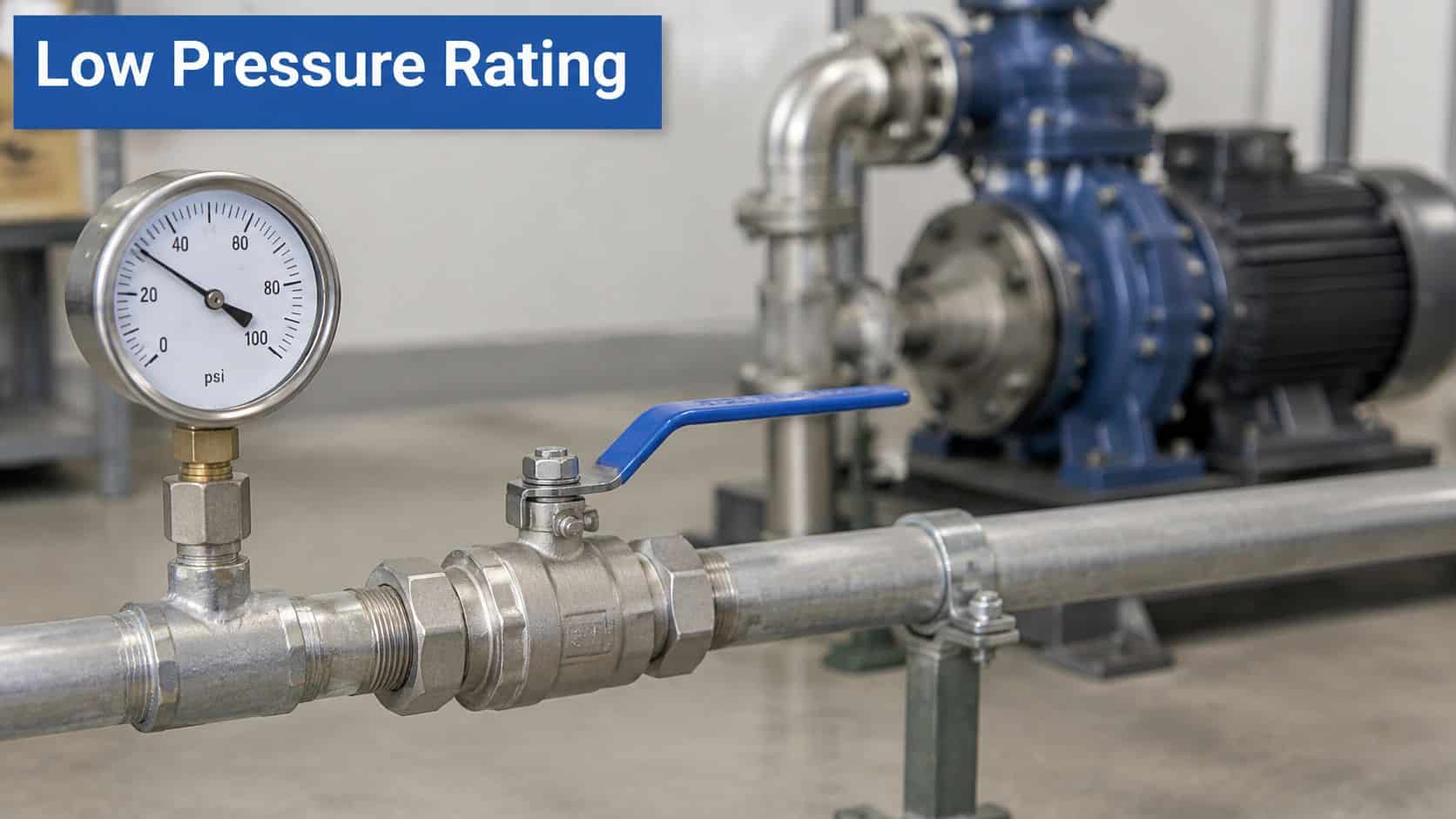
Inside the body, a bored ball rotates with the stem. Seats bear against the ball to provide shut-off, while separate seals prevent leakage around the stem and body joints. The handle gives a quick operating action, but it doesn't tell you what those internal materials can tolerate.
Bore and body construction matter
A full-bore valve keeps the passage close to the connected pipe's internal diameter. A reduced-bore valve introduces a smaller passage, which can be acceptable for a drain point but adds restriction where you need sustained flow. Choosing solely by connection size misses that difference.
Two-piece bodies are a common practical choice for straightforward isolation. Serviceable three-piece designs can allow the centre section and seats to be removed while the pipe-connected ends remain in place, provided there's sufficient access and the manufacturer permits that maintenance method. That can justify a higher purchase price where dismantling pipework would be awkward.
A low pressure rating only becomes useful when it's paired with a temperature range, a size and compatible materials.
Approval is specific to the duty
The Water Regulations Advisory Scheme approval examples associated with the building-water specification include ball valves with a maximum working pressure of 16.0 bar and a maximum operating temperature of 99°C. Those are product-specific limits, not permission to apply those conditions to every potable-water valve or to assume that both maxima apply simultaneously.
For wholesome-water installations, check the actual approval entry and its conditions. For hydraulic duty, obtain the relevant fluid compatibility and operating documentation instead. Where the duty exceeds the candidate valve's envelope, assess a properly specified high-pressure ball valve rather than stretching a lower-rated product.
Seal Materials and Body Choices for Each Fluid
| Material | Suits | Limitation |
|---|---|---|
| PTFE seats | Water, air and many hydraulic oils | Damage from debris in dirty fluid |
| EPDM seals | Water, glycol and hot water | Swells in petroleum-based oils |
| NBR seals | Mineral hydraulic oils | Poor resistance to ozone and some hot fluids |
| FKM (Viton) seals | Oils, fuels and higher-temperature duties | Higher cost |
| Brass body | Water supply and drainage | Dezincification risk in some waters |
| Stainless steel body | Potable and hygienic duties, with suitable design and approvals | Higher cost |
Match the seals to the fluid and temperature, not just the pressure. Material names identify families, not universal performance guarantees. The compound, seat construction and complete valve design determine the permissible operating envelope.
PTFE seats are useful across many water, air and hydraulic-oil duties. Their broad compatibility doesn't protect them from grit dragged across the sealing surface. Clean assembly and suitable filtration can matter more than choosing an expensive body material.
EPDM is a useful choice for compatible water and glycol services. It's not a substitute for an oil-compatible elastomer in a mineral-oil circuit. Also check the glycol formulation and additives rather than approving the seal from the word glycol alone.
Choose the elastomer before the body finish
NBR is a practical starting point for many mineral hydraulic oils. Check the actual oil, its additives and the valve's permitted temperature range, especially near hot return flows. External exposure also matters where an elastomer is vulnerable to weathering or ozone.
FKM, often identified by the Viton trade name, can suit oils, fuels and hotter duties where the particular compound is approved. It costs more, and it isn't automatically the best choice for every hot fluid. Paying for a more expensive elastomer won't correct an unsuitable seat design or an incorrect body rating.
- Brass bodies: Practical for suitable building-water and drainage duties, but water chemistry can make dezincification resistance important.
- Stainless-steel bodies: Useful for compatible corrosive or hygienic services, but the grade, connections and internal finish still need checking.
- Complete seal sets: Confirm stem seals and body seals as well as the seats touching the ball.
Apply the choice to the actual fluid
Say you're selecting an isolation valve for a warm mineral-oil return line. An NBR- or FKM-sealed assembly may be a sensible candidate, subject to its datasheet; an EPDM-sealed water valve isn't a sound substitution merely because its pressure rating appears adequate.
Any generic material temperature range is only a preliminary guide. The manufacturer's complete-valve datasheet governs the final choice, and you should compare it with the highest temperature the system reaches, not its average running temperature.
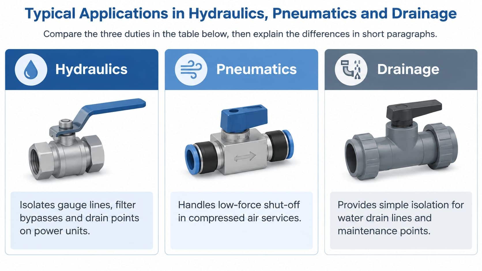
Typical Applications in Hydraulics, Pneumatics and Drainage
| Duty | Typical fluid | Seal to check | Key rule |
|---|---|---|---|
| Hydraulics, gauge lines, filter bypasses and drain points | Mineral hydraulic oil | NBR or FKM elastomers, with compatible seats | Confirm compatibility with the actual oil formulation |
| Pneumatics, compressed-air isolation | Dry compressed air | PTFE seats and air-compatible stem seals | Keep working pressure comfortably within the approved envelope; air approval doesn’t cover oil |
| Drainage and water, supply, drain-off and irrigation | Water | EPDM seals or PTFE seats | Use a suitable brass or stainless body for isolation duty |
The connection arrangement may look similar across these services, but the operating risks differ. Choose the valve for the fluid, the possible pressure exposure and the maintenance task it must support.
Hydraulic service points
Gauge branches, drain points and suitable filter-bypass arrangements are practical isolation duties. However, a small branch connected to a pressure gallery can experience the gallery's full pressure. Its small diameter doesn't make it low pressure.
Return lines also need careful assessment. A blocked filter, cold viscous oil or an incorrect operating sequence can produce conditions well beyond normal return pressure. Check every credible source of pressure before treating the location as a low-pressure service point.
Compressed-air isolation
For pneumatics, confirm the valve is approved for compressed air and establish whether the supply is dry, lubricated or likely to carry condensate. A water-compatible valve isn't automatically an appropriate air-isolation device. Consider how the downstream equipment will be exhausted after isolation.
Closing a supply valve can leave stored air downstream. Where maintenance requires depressurisation, provide a suitable means of venting and verify that pressure has been released before work starts.
Water and drainage duties
Supply, drain-off and irrigation valves usually need dependable shut-off rather than precise regulation. Debris, scale and infrequent operation can be more important selection factors than a compact handle or polished finish.
Use an isolation valve for isolation. For sustained throttling, choose a suitable needle valve, globe valve or purpose-designed control valve.
Leaving a standard ball valve partly open concentrates flow around the seat edges and can accelerate wear. A valve approved for air shouldn't be assumed suitable for oil, and an oil-service component shouldn't be transferred into drinking-water service without the appropriate evidence.
Compliance Checks for Great Britain Installations
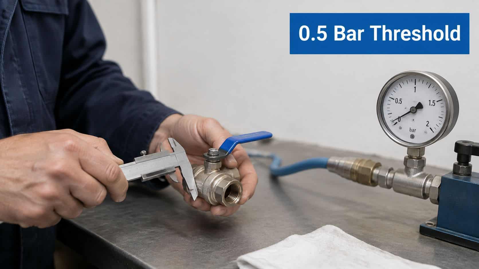
A low-pressure label doesn't settle the regulatory position. The HSE guidance on the Pressure Equipment (Safety) Regulations 2016 explains that the regulations generally apply to equipment and assemblies with a maximum allowable pressure, PS, greater than 0.5 bar.
That is a regulatory threshold, not a definition of low pressure. Classification, exclusions and the intended assembly determine the applicable route, so a relatively modest hydraulic or pneumatic duty can still require a documented assessment.
Keep an integration record
For OEM integration, record more than the supplier's part number. Keep the relevant information with the technical documentation:
- Maximum allowable pressure: Record PS rather than substituting normal operating pressure.
- Maximum allowable temperature: Identify the limit applying to the supplied assembly.
- Medium: Name the fluid and any compatibility-critical additives.
- Installation orientation: Record restrictions and necessary maintenance access.
- Isolation function: Explain what the valve isolates and how residual pressure is released.
Equipment below the relevant classification limits still needs sound engineering practice and adequate instructions. For equipment placed on the Great Britain market, applicable marking and conformity assessment depend on category and exclusions; operating instructions must be supplied in English.
Assess the system as well as the component
A manifold or power-pack assembly needs assessment as an assembly. Its pressure boundary, connected equipment and protective devices can affect the compliance route. Buying individually documented components doesn't, by itself, complete that assessment.
Keep supply conformity separate from in-service examination. Most qualifying pressure systems require a written scheme of examination prepared or certified by a competent person, covering the relevant vessels, pipework and protective devices. Not every hydraulic installation has the same examination obligations.
Decide whether PE(S)R applies, record PS and the medium, establish the examination position and retain the documents with the equipment. Use HSE guidance and a competent assessment for your specific system, rather than treating a catalogue description as compliance evidence.
How to Install and Test a Low Pressure Ball Valve
-
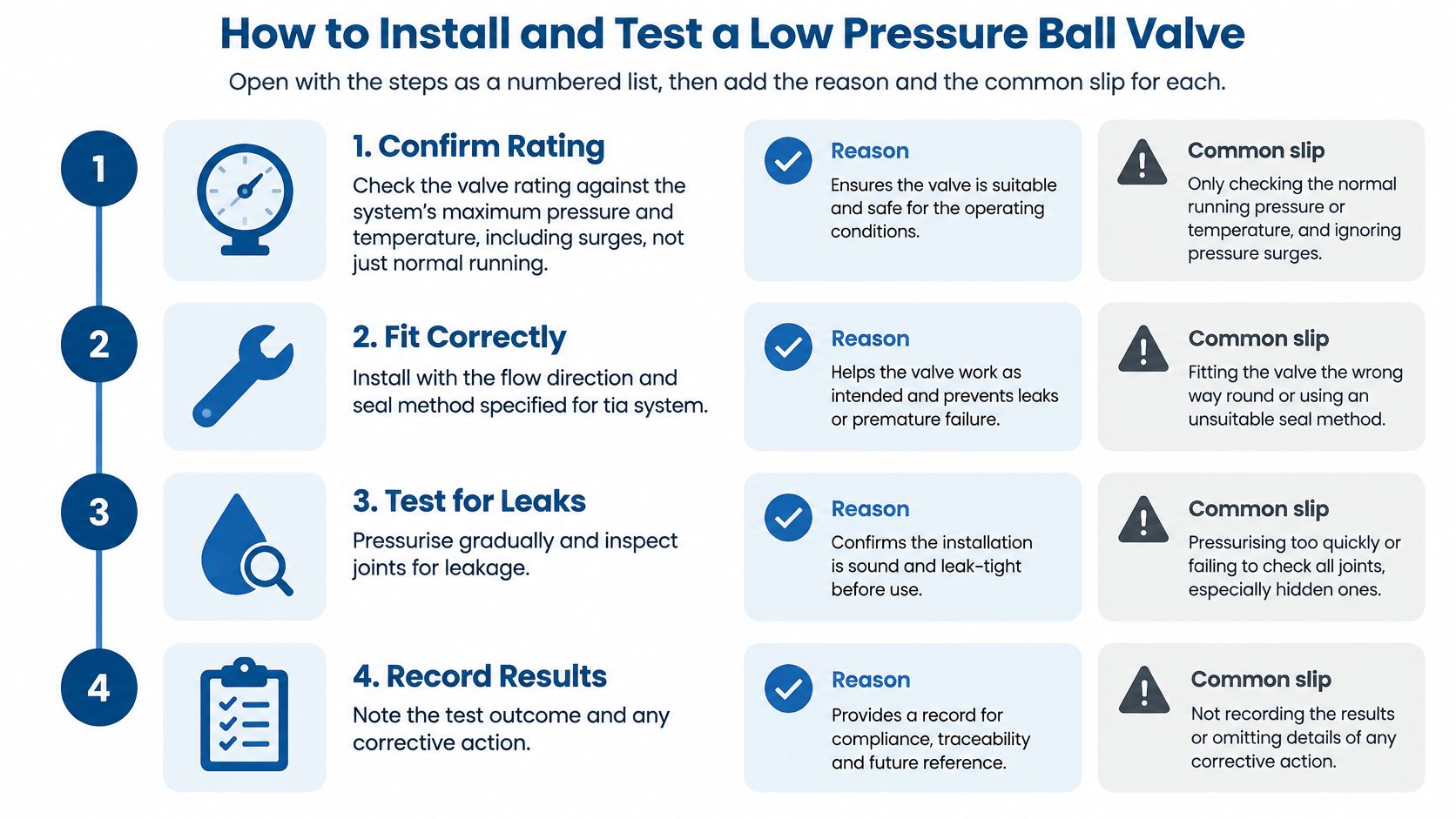
Confirm the complete operating envelope. Check maximum system pressure and temperature, including surges, against the body, seats, seals and end connections. Don't select from normal gauge pressure alone.
-
Check direction and handle indication. Follow any flow arrow and the manufacturer's orientation instructions; some designs are directional, although many standard isolation valves are bidirectional. Assuming every ball valve works identically can compromise sealing or cavity relief.
-
Support the pipework and leave operating clearance. Align the connections without pulling the pipe into position with the valve. Use a correctly sized spanner on the appropriate body flats, not the handle, and prevent bending loads reaching the ports.
-
Use the correct joint seal. Apply a fluid-compatible thread sealant only where the connection requires it, keeping excess away from the bore. Don't apply tape indiscriminately to connections that seal on a washer, cone or O-ring.
-
Clean, inspect and operate before pressurising. Flush debris from the pipework, then cycle the handle fully to confirm smooth movement. Cycling alone doesn't remove contamination, and dragging grit through the seats can damage them before commissioning.
-
Protect trapped liquid. Provide suitable pressure relief wherever liquid can become blocked in and heated. Don't assume an external line-relief device also protects an isolated internal ball cavity; check the valve's cavity-relief design.
-
Leak-test under an approved procedure. For a commissioning leak check, increase pressure gradually to the specified level within the installed assembly's allowable limits, then inspect every joint. A formal proof test is a different operation and must follow its own authorised procedure.
-
Verify status and record the result. Check that the handle and any labels unambiguously identify open and closed positions. Rectify defects, repeat the relevant checks and retain the final result before releasing the system for use.
Test the assembly, not just the valve
HSE pressure-system user guidance requires users to establish safe operating limits, provide suitable protective devices and ensure equipment is suitable and correctly installed. Apply that system-level approach when planning the commissioning leak test, rather than treating the valve's catalogue rating as the test instruction.
Check the downstream components against the pressure the pump or supply can deliver. If any component has a lower allowable pressure, the protective arrangement must prevent that limit being exceeded. A higher-rated valve doesn't protect a lower-rated hose or instrument.
Control the test and retain the evidence
Establish an exclusion area, use suitable calibrated instruments and keep people away from potential release paths. Never tighten a leaking connection while it's pressurised. Isolate, depressurise, rectify and retest.
Use a documented pressure-testing procedure that identifies the test medium, pressure, acceptance criteria and safe release method. Record the test pressure, date, person responsible, defects found and corrective action. Keep that record with the equipment so the next maintenance engineer can distinguish a verified installation from an undocumented replacement.
Common Faults and Fixes
Depressurise and verify isolation before adjusting or dismantling the valve. A closed handle isn't proof that the downstream equipment is safe to open.
Leakage and difficult operation
- Seat leakage when closed: Debris or damaged seats can allow fluid past the ball. Flush the line safely, confirm fluid compatibility and replace the correct seat kit if leakage persists.
- Stem or gland leakage: Where the design has an adjustable gland, make only the permitted small adjustment and recheck. If leakage continues after operation, replace the stem seal rather than repeatedly tightening the gland.
- Stiff or seized handle: Investigate scale, contamination or damaged sealing surfaces. Move the handle cautiously only when safe, and never use an extension bar to overcome unexplained resistance.
Material damage and lost movement
- Swollen, softened or hardened seals: Suspect chemical incompatibility or excessive temperature. Identify the installed compound and replace it with an approved material after correcting the underlying duty.
- Pink-brown or pitted brass: This can indicate dezincification or other corrosion, but colour alone isn't a diagnosis. Replace a weakened body and assess water chemistry before choosing a suitable resistant brass or stainless alternative.
- Handle movement without a flow change: Check for a loose handle connection or failed stem-to-ball drive. Isolate elsewhere, release pressure and inspect rather than trusting the handle position.
Replace by identity, not appearance. Order seat kits and stem seals against the valve's make, model, size and datasheet. Don't mix internal parts between manufacturers.
For plants managing many isolation points, AI for Manufacturing's factory predictive maintenance use cases offer context for organising condition information. Start with useful maintenance records: leakage location, operating stiffness, fluid condition and replacement reason. Monitoring can help prioritise intervention, but it doesn't make a leaking isolation valve safe.
Confirm Your Valve Choice Before You Order
A listed price applies to a specific specification, not to low-pressure ball valves as a category. For example, STAUFF UK lists its 2-inch BSP female/female low-pressure ball valve at £334.82 per piece in 2026. Compare like-for-like specifications and check the live quotation before ordering.
BSP connection designations use established trade naming. Give the exact thread description and measured dimensions when identifying a replacement, rather than substituting a metric pipe measurement. A photograph can help identify the connections, but it cannot confirm the internal seal compound.
Send a duty specification with the enquiry
Provide enough information for procurement and the supplier to assess whether an alternative suits the application:
- Fluid: Specify the oil grade, water service or air condition.
- Pressure: State normal operation and the maximum possible exposure.
- Temperature: Give normal and maximum conditions.
- Size and connections: Include nominal size, thread type, end arrangement and required clear bore.
- Materials: Identify preferred seals and any body-material restrictions.
- Regulatory route: State applicable PE(S)R requirements and whether potable-water approval evidence is needed.
Ask for the datasheet, pressure-temperature information and relevant test certificate with the quotation. If flow restriction matters, specify the passage required. A matching connection alone does not confirm a full-bore valve.
Confirm availability before committing
Confirm ball valve availability with MA Hydraulics Ltd before ordering. For wider circuits, the company offers Hoyea modular check, flow control, reducing and relief valves, CETOP directional valves and steel manifolds. Its OMT Group range includes cross relief, flow divider/combiner, overcentre, pilot-operated check, pressure reducing, priority flow control, pump unloader, relief, sequence and solenoid valves.
Base the decision on the application and supporting documentation, not only the line price. A replacement that matches the duty and connections is less likely to cause avoidable disruption than one chosen by appearance alone.
MA Hydraulics Ltd offers hydraulic component selection support and bespoke power solutions, helping you match an isolation valve to its fluid, connections and operating conditions. Send us a message with your valve details so we can help assess the requirement and confirm availability before you order.
