
The most common advice about a hydraulic filter kit is also the least useful: replace the element at a fixed interval and move on. That approach treats filtration as a consumable cost rather than a diagnostic system. If a new element blocks early, the filter may be reporting a breather problem, cold oil, component wear or contamination introduced during filling.
A properly selected kit protects pumps, valves and motors, but it also gives maintenance teams evidence about what is happening inside the circuit. The objective is not just to fit a filter that matches the old part. It's to control contamination, preserve hydraulic performance and understand why restriction changes over time.
Understanding the Role of a Hydraulic Filter Kit
A filter kit isn't an interchangeable commodity just because two elements share a nominal micron description. The housing, media, seals, bypass setting, flow direction and dirt-holding capacity all affect whether the assembly protects the circuit or becomes a restriction that the system tries to bypass.
Particle contamination is particularly damaging to gear pumps, proportional valves, servo components and hydraulic motors. Hard particles can score surfaces, interfere with valve spools and accelerate leakage. Once wear creates more debris, the system can enter a damaging cycle where contaminated oil produces component wear, and that wear produces still more contamination.
The UK market reflects the importance of filtration in demanding circuits. The UK hydraulic and lube filters market generated USD 189.5 million in 2022, and pressure-side filters held a 37.04% revenue share, reflecting their use in high-pressure industrial and mobile systems, according to the UK hydraulic and lube filters market outlook. The same source projects the market to reach USD 212.0 million by 2030, with a 1.4% CAGR over the forecast period. If a USD example is used for commercial comparison, UK buyers should request a current GBP equivalent from the supplier rather than assuming a direct conversion or fixed price.
Why placement matters
A return-line filter protects the reservoir from contamination returning from actuators and valves. A pressure-line filter gives sensitive downstream components a cleaner supply, while a suction-line strainer helps prevent larger debris from reaching the pump without imposing excessive inlet restriction.
The right location depends on the circuit's contamination risk and the component being protected. A high-efficiency element installed in the wrong position can create unacceptable pressure drop, especially during cold starts. Conversely, a coarse strainer may keep large debris away from a pump but won't provide the control required by precision valves.
Practical rule: Specify the complete filtration assembly, not just the replacement element. The housing, indicator, seals and bypass behaviour are part of the protection strategy.
The UK has a long engineering history of separating contaminants from fluids. A sand filter was installed for public water treatment in Paisley, Scotland, in 1804, James Simpson developed a treated public water supply in London in 1829, municipal water filtration became obligatory across Britain in 1852, and automatic pressure filters were invented in England in 1899, as described in this history of British filtration engineering. Hydraulic filtration developed within that wider culture of managing contamination under both gravity and pressure.
Exploring Filter Element Types and Media Options
Filter media should be chosen according to the fluid, temperature, contamination target and circuit duty. No single material wins in every application. The practical decision is a trade-off between efficiency, cost, dirt-holding capacity, pressure-drop behaviour and serviceability.
Cellulose for straightforward duties
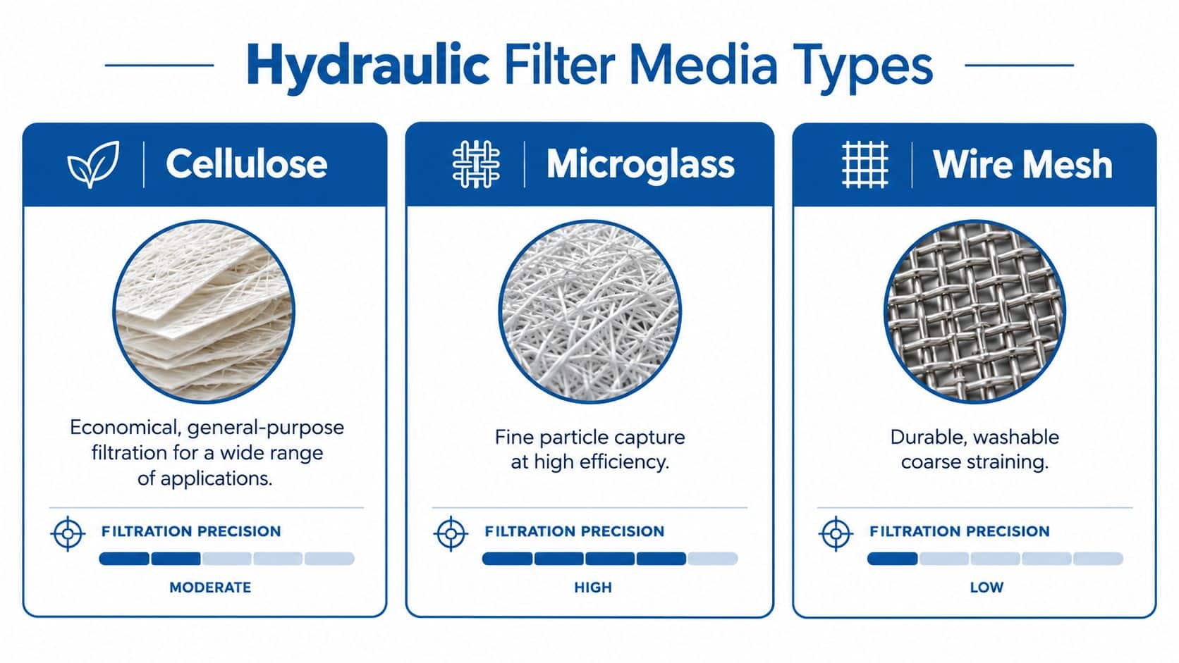
Cellulose media is often selected for general-purpose hydraulic filtration where operating conditions are moderate and procurement cost matters. Its paper-based fibres can provide effective protection for less demanding circuits, but performance depends on construction quality, fluid compatibility and the cleanliness target.
Cellulose isn't automatically a poor choice. It can be appropriate where the circuit has a sensible contamination-control regime and the element is replaced before restriction becomes excessive. The mistake is treating an economical element as a universal substitute for a higher-efficiency design in a sensitive pressure circuit.
Microglass for higher efficiency
Microglass media uses fine synthetic fibres to capture smaller particles with greater consistency. It's commonly considered for high-efficiency applications, pressure circuits and systems where maintaining a cleaner fluid is more important than minimising initial element cost.
The trade-off is that a finer, higher-efficiency element can load rapidly if the circuit has an uncontrolled contamination source. That doesn't mean the media is unsuitable. It means the maintenance team must monitor differential pressure and investigate abnormal loading instead of assuming the element has failed.
Wire mesh where durability matters
Wire mesh provides a durable, washable medium for coarse straining and applications where mechanical durability is important. It can suit suction protection or circuits where the primary objective is to stop larger particles from reaching a pump.
Mesh isn't a direct replacement for fine hydraulic filtration. Its open structure may allow particles through that a microglass element would capture, so it should be matched to the component tolerances and cleanliness requirement. Cleaning must also be controlled. A damaged mesh, poor inspection or incomplete removal of debris can return contamination to service.
| Media | Useful strength | Main limitation |
|---|---|---|
| Cellulose | Economical general-purpose filtration | Less suitable for the most contamination-sensitive duties |
| Microglass | Fine particle capture and high efficiency | Can load quickly when contamination sources are uncontrolled |
| Wire mesh | Durable, washable coarse straining | Doesn’t provide the same fine filtration as specialist media |
Fluid viscosity and temperature also matter. A filter that performs acceptably with warm oil may create excessive restriction during a cold start. For mobile machinery operating outdoors, the element must be assessed against the actual start-up condition, not only steady-state flow.
Decoding Micron Ratings and Beta Efficiency Standards
A micron figure on its own doesn’t tell you enough. The label may describe a nominal rating, which indicates approximate capture performance under a particular test method, while another element with the same stated micron size may deliver very different efficiency in service.
The more useful specification is the beta ratio. It compares the number of particles upstream with the number downstream at a stated particle size. A higher beta ratio indicates that fewer particles of that size pass through the element under the test conditions.
Read the test method, not just the label
For UK industrial systems, filter performance should be validated against BS ISO 16889:2022, the British Standard implementation of ISO 16889. The standard uses a multi-pass method to assess the element’s beta ratio under controlled contaminant loading, as explained by the British Fluid Power Association’s fluid power standards guidance.
That matters because two elements can both be described as a particular micron size while differing materially in efficiency, lifespan and pressure-drop growth. A procurement team that compares only the micron number risks accepting a false equivalent.
Ask the supplier for the beta rating at the relevant particle size and confirm the test standard. Then consider how that result fits the circuit’s target cleanliness. The filter must remove particles effectively without reaching bypass too quickly.
Connect filtration to cleanliness
The ISO cleanliness code guidance for hydraulic systems helps teams translate a cleanliness target into a practical maintenance requirement. The target should reflect the most sensitive component, the fluid, operating pressure and the consequences of failure.
A useful specification records:
- Test standard: Confirm that the efficiency claim is based on BS ISO 16889:2022 or an equivalent, clearly identified method.
- Beta rating: Record the ratio and particle size rather than accepting “high efficiency” as a description.
- Element capacity: Check dirt-holding performance alongside initial efficiency.
- Pressure-drop curve: Review behaviour at the actual flow and viscosity range.
- Bypass behaviour: Confirm when unfiltered oil can pass through the assembly.
Nominal ratings still have a place in product identification, but they shouldn’t be the final purchasing criterion. The engineering question is whether the element delivers the required contamination control for the complete operating cycle.
Matching Sizing and Compatibility to Your System
A high-efficiency element can’t compensate for an undersized housing. Start with the circuit’s actual flow, maximum operating pressure, fluid viscosity and cold-start condition. Use pump displacement and operating speed to estimate flow, then allow for the possibility that several actuators or pump sections may contribute to the filter’s demand.
The selected assembly should operate with an acceptable pressure drop at normal flow and remain safe as the element loads. A filter that looks suitable at warm-oil conditions may become restrictive when the machine starts in cold weather. Check the manufacturer’s pressure-drop information rather than sizing from port diameter alone.
Verify the bypass setting
The bypass valve protects the element and housing when restriction becomes excessive. It helps prevent element collapse or burst, but it can also allow contaminated oil to pass when the element is loaded, so its setting must suit the circuit.
Standard filter assemblies normally use bypass settings between 0.8 and 7 bar, while suction-line filters may use low settings such as 0.14 bar or 0.2 bar to reduce cavitation risk and prevent element collapse, according to this Parker hydraulic filtration guide.
Suction filtration deserves particular care. Excessive inlet restriction can cause cavitation, noise, erratic pump operation and damage. A pressure-line filter can tolerate a different restriction strategy from a suction-line filter, so don’t transfer the bypass specification from one circuit position to another.
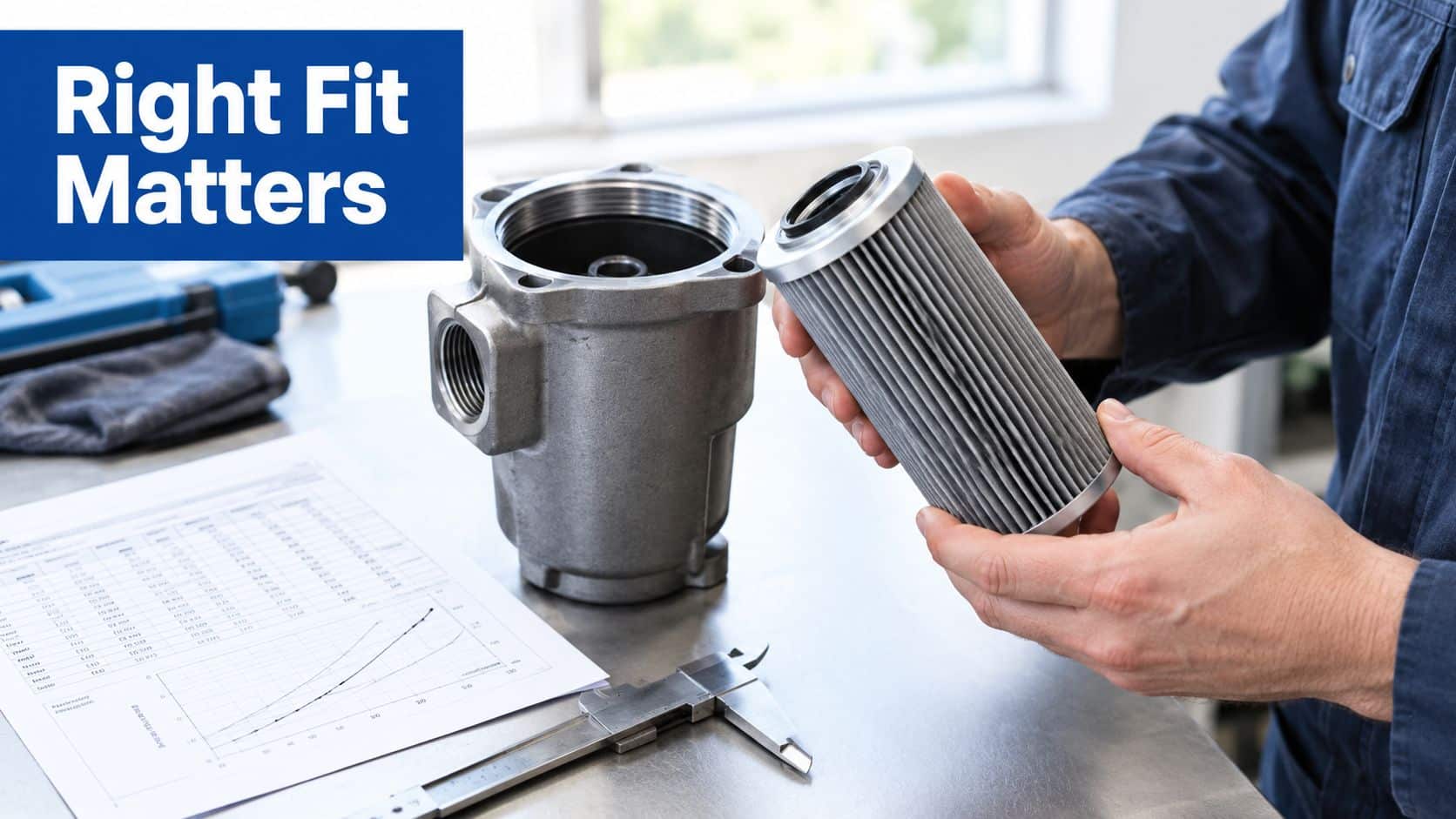
Check physical compatibility
Before ordering, compare the old and new assembly against the machine drawings and the actual installed parts. Confirm:
- Port size and thread form, including whether the connection is metric, BSP or another standard.
- Flow direction, shown by the housing arrow or circuit drawing.
- Seal material, matched to the hydraulic fluid and temperature.
- Envelope dimensions, including element length, lid clearance and service access.
- Pressure rating, based on the line’s maximum pressure and transient conditions.
- Indicator connection, including visual, electrical or differential-pressure monitoring.
A hydraulic filter housing selection guide can help identify the housing, port arrangement and service requirements before the element is specified. Don’t force a physical fit by modifying seals, threads or flow direction. A kit that needs improvised adaptation isn’t a controlled replacement.
Implementing Evidence-Led Maintenance and Installation
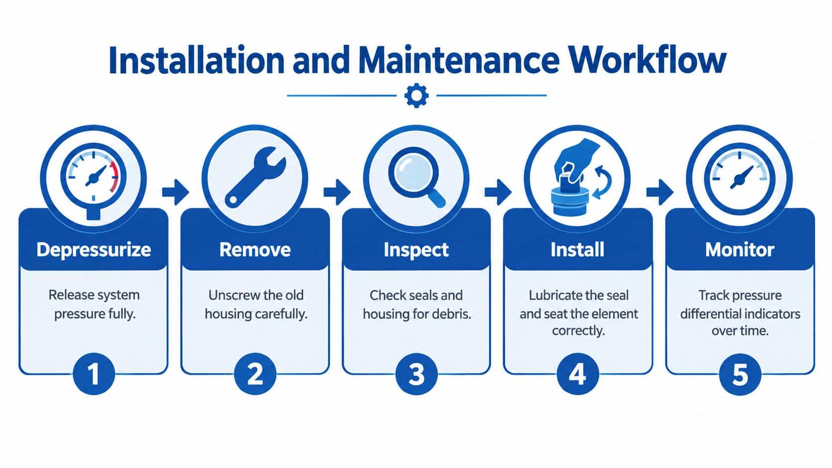
Installation quality determines whether a good element performs properly. Depressurise the circuit, clean the housing exterior, remove the old element without dropping debris into the open assembly and inspect the sealing surfaces. Lubricate compatible seals with clean hydraulic fluid, seat the element correctly and verify the flow arrow before closing the housing.
After installation, prime the circuit where required and bleed trapped air in accordance with the machine procedure. Air introduced during service can cause noise, erratic actuator movement and misleading pressure readings. Check for leaks at operating temperature, then record the element identity, operating hours and initial differential-pressure reading.
Replace by evidence, not habit
Calendar intervals are useful starting points, but they shouldn’t be the entire maintenance policy. A differential-pressure indicator shows how the element is loading, while oil sampling helps identify contamination that the filter alone can’t explain.
New equipment deserves special treatment. The recommended initial filter change is after 50 hours to remove break-in contaminants, followed by changes at 250 to 500 hours or six months, depending on duty cycle and contamination profile, as set out in this hydraulic filter replacement guidance.
Mature equipment may need a different pattern. A clean, stable machine with consistent readings shouldn’t automatically receive the same intervention as a dusty mobile machine, a heavily loaded press or equipment showing repeated debris. Record trends and adjust the schedule when the evidence changes.
A practical service record includes:
- Machine and circuit identification, including filter position.
- Element part number and media, including any approved cross-reference.
- Operating hours and oil temperature, especially during restriction checks.
- Differential pressure, recorded under comparable operating conditions.
- Oil sample result, where contamination or component wear is suspected.
- Removed-element inspection, noting metallic debris, seal damage or sludge.
The hydraulic oil analysis service adds another layer of evidence when differential pressure rises unexpectedly or a component shows signs of wear.
Diagnosing Common Failure Modes and Contamination Sources
When a hydraulic filter kit blocks early, replacing it without investigation often hides the actual fault. Start by comparing differential-pressure readings across the suction, return and high-pressure filters. The pattern matters more than one isolated reading.
A return filter that loads rapidly may be receiving debris from a worn actuator, valve or pump. A suction filter showing an unexpected restriction during a cold start may point to high oil viscosity, an unsuitable element or an obstructed inlet. If several readings change after the reservoir is sealed, inspect the tank breather. A blocked breather can interfere with tank pressure and oil movement, while a damaged breather can admit contamination.
Follow the contamination trail
Remove and inspect the old element carefully. Fine metallic material suggests component wear, while fibrous debris, seal fragments or sludge points towards different sources. Check the reservoir, filler strainer, hose interiors, cylinder rods and recent maintenance activity.
Bulk and drum-supplied oil can arrive with 2 to 20 times more particles than levels acceptable for many hydraulic systems, making controlled transfer, offline filtration and consistent sampling important, as explained in the hydraulic filter selection guidance. A new element may therefore be doing exactly what it should while removing contamination introduced during filling.
The target cleanliness level should be based on the machine’s components and duty. A common UK baseline is ISO 4406 19/17/14, while more contamination-sensitive systems may target around 16/14/11. The maintenance team should use the cleanliness code with differential-pressure history, oil analysis and component condition rather than treating it as a standalone number.
Treat early blockage as evidence
Contamination above ISO Code 19/17/14 can raise wear rates by 300% to 400%, while maintaining cleaner oil below Code 16/14/11 can extend pump and valve life by 25% to 30%, according to this preventive hydraulic maintenance guidance. Those figures make a blocked element more than a replacement cost. It can be an early warning that the system is operating outside its intended cleanliness control.
Diagnostic rule: Don’t condemn the element until you’ve checked the breather, oil viscosity, fill practice, upstream components and differential-pressure trend.
If a replacement element blocks at the same point in the circuit and under the same operating condition, look for a repeatable cause. Record the machine state when the indicator changes, including start-up temperature, recent component work and oil additions. This turns an unwanted filter change into useful failure evidence.
Using a Specification Checklist for Bespoke Orders
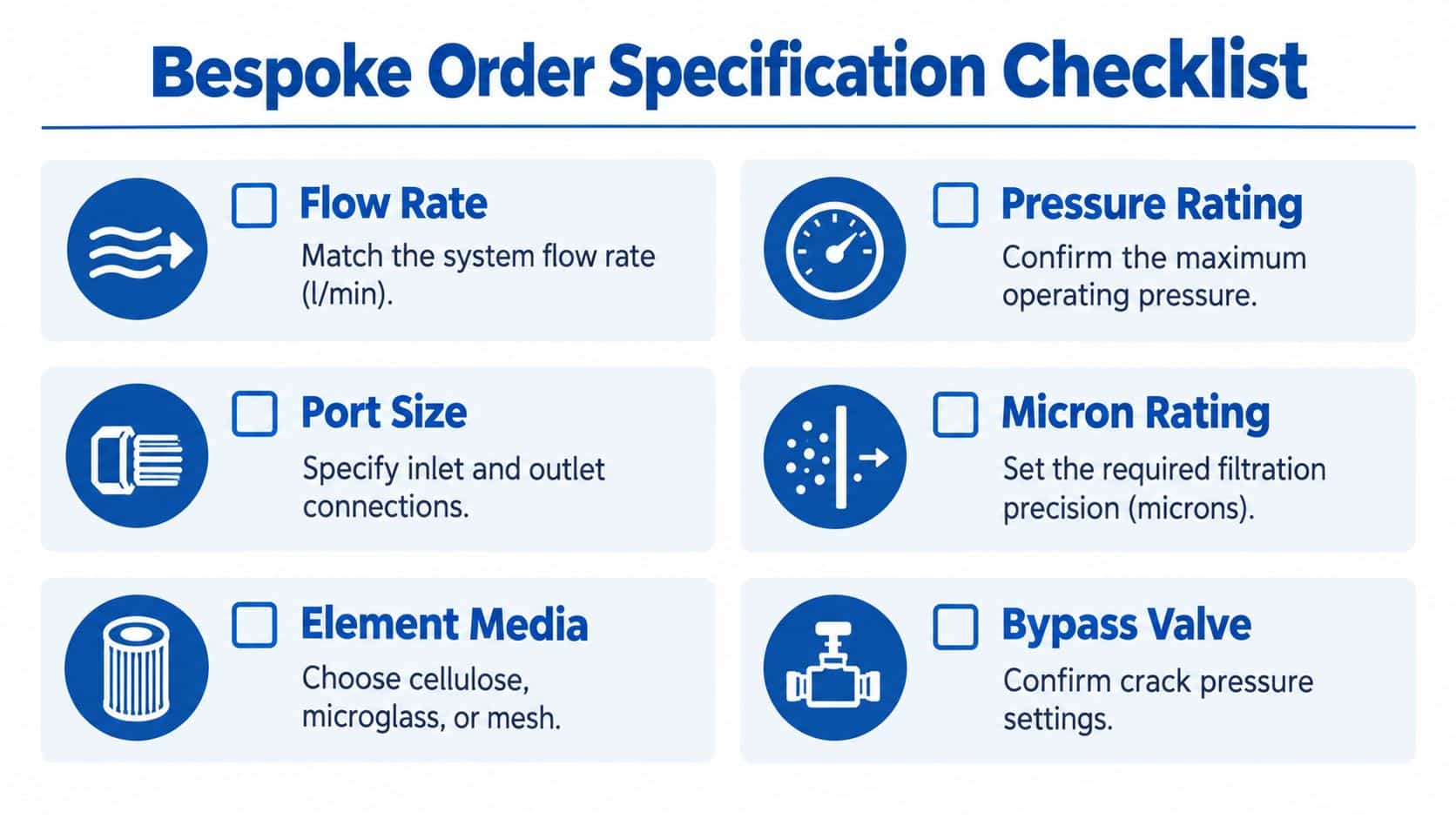
A bespoke hydraulic filter kit should be specified from circuit data, not from a photograph of an old element. Legacy labels fade, cross-references can be incomplete and similar housings may use different seals or bypass valves. Procurement should gather enough information for the supplier or design engineer to verify the complete assembly.
Record the operating facts
Start with the machine and circuit position, then document the following:
- Flow rate: State normal and maximum flow in metric units, including the pump arrangement and any simultaneous functions.
- Pressure rating: Record normal, peak and transient pressure for the selected line.
- Port size: Confirm inlet and outlet connections, thread form and orientation.
- Micron and beta requirement: Specify the cleanliness objective and require test information rather than a nominal micron claim alone.
- Element media: Choose cellulose, microglass or wire mesh according to duty, fluid and service conditions.
- Bypass valve: State the required crack pressure and whether an indicator or electrical switch is needed.
- Fluid and seals: Identify the hydraulic fluid, temperature range and seal material.
- Dimensions: Provide housing length, service clearance, mounting details and flow direction.
- Maintenance information: Include expected operating hours, contamination history and any early blockage reports.
A clear photograph can help with identification, but it shouldn’t replace measurements and circuit information. Include the old part number where legible, the machine make and model, housing markings and the dimensions of the removed element. For a bespoke power pack, provide the schematic and specify whether the filter protects the pump inlet, return flow or a sensitive downstream manifold.
Control oil added to the system
Top-up oil is part of the contamination-control plan. Don’t assume sealed drums or bulk containers are clean enough for a sensitive circuit. Filter transferred oil before it enters the reservoir, use dedicated clean containers and prevent filler equipment from becoming a contamination source.
Offline filtration, sometimes known as kidney-loop filtration, can reduce reservoir contamination without forcing the main circuit to operate through an undersized element. It works alongside the installed filter rather than replacing the need for correct in-line protection. Sample the oil consistently so changes can be compared over time.
MA Hydraulics Ltd supplies hydraulic components and bespoke power solutions, including filter selection support, cross-referencing assistance and complete assemblies for mobile and industrial applications. A specialist supplier can help resolve hard-to-read part numbers, check compatibility and match the kit to flow, pressure, cleanliness and cold-start requirements.
The most reliable order is one supported by evidence. Send the supplier the machine details, circuit position, old element information, operating conditions, contamination history and photographs of the housing and connections. That gives the design team enough information to recommend a controlled replacement instead of a guess based on appearance.
For hydraulic filter kit selection, cross-references, filtration components and bespoke power-pack support, contact MA Hydraulics Ltd on 01724 279508. The team can help match filtration to your circuit and source hard-to-find parts, or you can visit MA Hydraulics Ltd to send a message through the website.
