
A filter warning appears during a busy shift. The machine still moves, the oil looks reasonably clean, and production needs the equipment back in service. The tempting response is to remove the element, wash it, refit it and carry on.
That approach can create a larger failure. Hydraulic filter servicing is a controlled contamination-exclusion task, not merely a cleaning job. You need to protect people from stored pressure, protect the circuit from new dirt, identify what the filter has captured, and dispose of contaminated oil and materials correctly.
Why Visual Inspection Is Not Enough for Hydraulic Filters
A hydraulic filter can look clean and still be doing a poor job. Clear oil and an element with no obvious sludge tell you very little about the particles circulating through pumps, valves, cylinders and motors.
UK hydraulic cleanliness is commonly recorded using ISO 4406 particle-count codes. The code measures particles larger than 4, 6 and 14 micrometres per millilitre, providing a much more useful picture than an inspection by eye. In the relevant band, code 19 represents approximately 2,500 to 5,000 particles per millilitre, while code 14 represents approximately 80 to 160 and code 11 represents 10 to 20 particles per millilitre. These figures are set out in MA Hydraulics' explanation of ISO cleanliness codes.
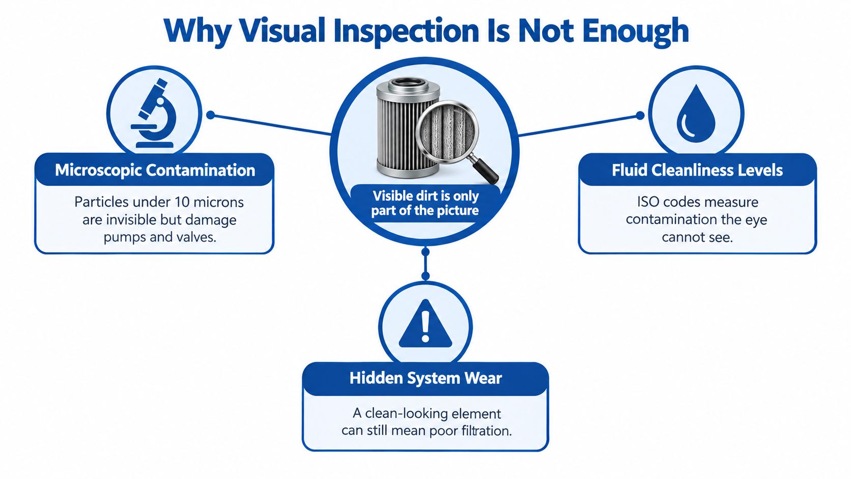
That difference changes the maintenance decision. Oil that looks bright may still contain enough fine contamination to accelerate wear in close-tolerance components. A filter element can also be incorrectly fitted, damaged, bypassing or unsuitable for the required flow and filtration rating while appearing perfectly normal.
Use inspection as evidence, not proof
Before opening a housing, record the filter location, element part number, operating hours, oil temperature and any differential-pressure indicator reading. Take a photograph of the installed arrangement and retain the removed element where possible. Those records help you compare a clean-looking element with actual oil condition and machine behaviour.
A filter service has succeeded only when the system returns to the required operating condition. Check for leaks, confirm that restriction is normal and use an oil sample or particle count when contamination is suspected. The equipment's specified ISO 4406 target matters more than a general statement that the oil “looks clean”.
Practical rule: A clean-looking element proves only that you can't see much contamination. It doesn't prove that the hydraulic circuit is clean.
Contamination can enter through breathers, open ports, poor storage, damaged seals or unfiltered oil transfer. It can also be generated inside the circuit by worn pumps, valves, hoses and cylinders. Cleaning or replacing the element without investigating those paths may leave the original fault in place.
Essential Safety and Depressurisation Procedures
Never loosen a filter bowl or cap until the machine has been isolated and the pressure state has been verified. Hydraulic fluid can remain trapped behind the element after the pump stops, and a suspended load or actuator can still move if stored energy isn't controlled.
The UK Health and Safety Executive requires maintenance to be carried out by competent people with suitable information, instruction and training under PUWER Regulations 8 and 9. Its maintenance guidance also requires pressurised plant and pipelines to be isolated, with isolating valves locked off where appropriate. The relevant HSE maintenance guidance supports a safe system of work rather than an informal workshop shortcut.
Establish zero energy before removal
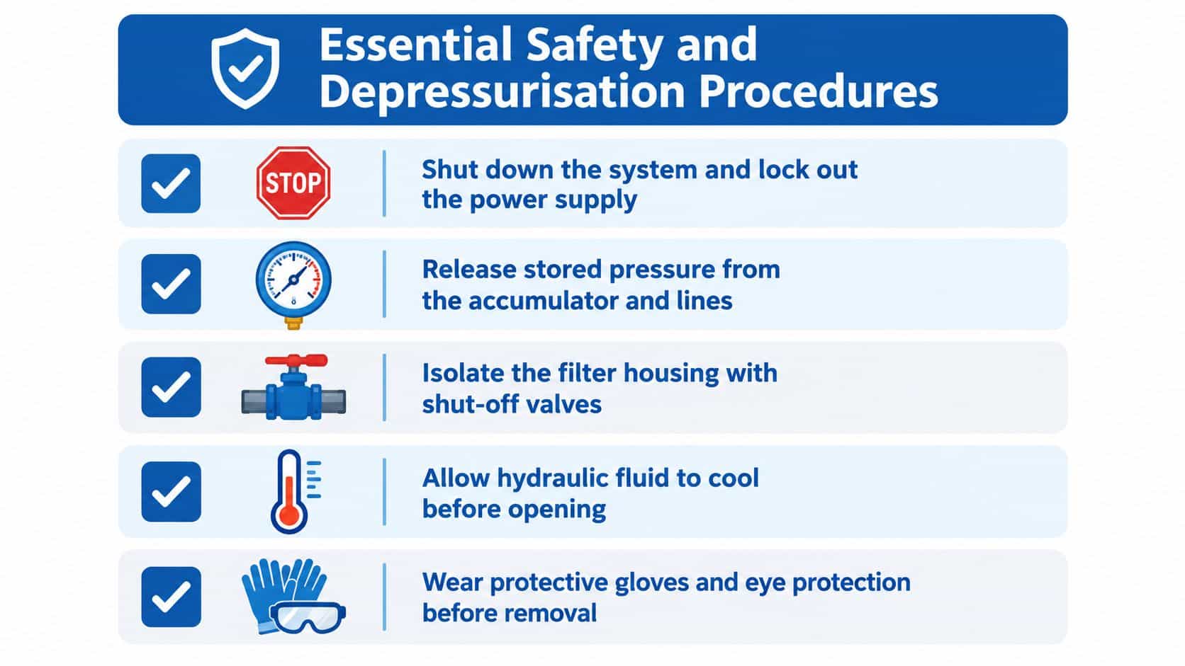
Use the manufacturer's procedure and work through the isolation sequence:
- Stop the prime mover and isolate electrical, engine or PTO energy. Apply the site's lockout and tagout controls.
- Lower suspended loads or support them mechanically. Don't rely on hydraulic pressure to hold an attachment, boom, platen or lift table.
- Isolate the filter housing using the correct shut-off valves where the circuit design permits. Lock them off when appropriate.
- Release stored hydraulic pressure from accumulators and trapped lines through the approved controls or test points.
- Verify zero pressure with the correct gauge or test point before loosening the housing.
HSE warns that hydraulic injection injuries can occur at pressures as low as 7 bar, as explained in its guidance on hydraulic injection injuries. Never use your hand to find a leak. Use cardboard or another suitable method, keep your face and body away from suspected jets, and seek urgent medical attention after any suspected injection injury.
Allow hot oil and components to cool before opening the housing. Wear suitable gloves and eye protection, place a drain pan beneath the filter, and keep absorbent material ready without allowing loose fibres into the circuit. If the isolation method, pressure state or mechanical support isn't clear, stop the work and obtain competent assistance.
The embedded safety video below should be checked in the page preview to confirm that its frame renders at the intended aspect ratio rather than appearing stretched or cropped.
Step-by-Step Filter Removal and Cleaning Techniques
Once the system is demonstrably safe, contamination control becomes the priority. Have the correct replacement element, new seals where required, a suitable drain container, lint-free wipes, compatible cleaning fluid and clean caps or plugs ready before disconnecting anything.
Start by cleaning the outside of the filter head, bowl, cover and surrounding pipework. This step prevents loose dust falling into the housing when the seal is broken. Clean the area around hose connections as well, then cap hoses and ports immediately after disconnection.
Separate reusable parts from disposable elements
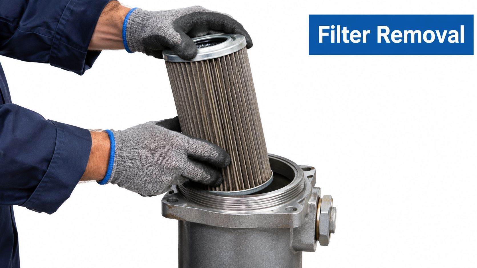
Remove the element carefully and keep debris from dropping into the bowl. Inspect it for collapsed media, damaged pleats, abnormal loading, metal particles, varnish and water-related contamination.
| Component | Suitable action | What to avoid |
|---|---|---|
| Reusable wire-mesh strainer | Clean in a compatible solvent or approved cleaning fluid, then dry thoroughly | Wire brushes, aggressive chemicals and contaminated solvent |
| Magnetic insert | Wipe clean and inspect for unusual ferrous debris | Returning it with captured particles still attached |
| Housing and bowl | Wipe with a lint-free cloth and clean compatible hydraulic fluid | Workshop rags that shed fibres |
| Disposable depth-media element | Replace with the correct specification | Washing it and assuming its filtration performance is restored |
Cleanable parts should be dried with filtered, low-pressure air directed from the clean side outward. High-pressure air can damage mesh, loosen fibres or drive contamination deeper into the element. If the element is wet, collapsed, damaged, heavily loaded or its cleanliness can't be verified, replacement is the safer option.
Inspect every sealing face. Replace any cut, flattened or hardened O-ring or gasket, and lightly lubricate seals with clean, compatible hydraulic fluid where the manufacturer permits it. Fit the element in the correct flow direction and use the manufacturer's specified housing torque. Under-tightening can cause leakage or air ingress, while over-tightening can damage the bowl or seal.
For compatible replacement options, confirm the part number, micron rating, flow capacity, bypass setting and seal material against the machine requirements. A hydraulic filter kit from MA Hydraulics may be suitable where the required element and associated sealing parts match the application.
Refill with clean, correctly specified oil. Don't pour directly from an unfiltered drum into an open reservoir. Restart at low load, check for leaks and abnormal noise, then verify restriction and fluid condition before returning the machine to normal duty.
Reading the Debris to Diagnose System Health
The removed filter is a record of what the hydraulic circuit has been carrying. Treating it as waste immediately can discard the earliest warning of pump, valve, hose or seal damage.
Photograph the element before disturbing the captured material. Look for the difference between ordinary fine loading and evidence of an active mechanical problem. Fine, evenly distributed debris may reflect normal operation or break-in, while concentrated metallic material, large fragments or a sudden change from previous services deserves investigation.
What different contamination can indicate
- Metallic particles may indicate wear in a pump, valve, motor, cylinder or other moving component. Use a magnet to distinguish ferrous debris, but remember that non-ferrous particles won't respond to it.
- Rubber particles can point towards deteriorating hoses, seals or flexible connections. Repeated rubber contamination shouldn't be solved by repeated filter replacement.
- Sludge or varnish may indicate degraded fluid, heat-related deposits, poor storage or contamination entering through the reservoir system.
- Water or milky fluid requires investigation of condensation, ingress, storage and sealing. Water can damage components and alter lubricant performance.
- Collapsed media or a distorted element may indicate excessive restriction, incorrect sizing, a blocked circuit or a bypass event.
Where practical, retain a sample of the removed element and take an oil sample from a representative live-flow point using clean equipment. A laboratory or suitable testing service can assess particle counts, water content and other condition indicators that visual inspection can't confirm. Hydraulic oil analysis support can help establish whether the correct response is an element change, flushing, component repair or a wider contamination investigation.
Parker's European hydraulic-filter reference attributes more than 85% of system failures directly to contamination. That figure is a reason to investigate contamination properly, not a reason to assume every dirty filter is the root cause. A bypassing element may have released retained dirt, while a new element with the wrong micron rating or bypass setting may fail to protect the circuit.
After reassembly, trend differential pressure, particle counts, water content and operating temperature where those measurements are available. If contamination is severe or recurring, inspect the reservoir, breathers, hoses, seals and damaged components before putting the machine back into routine service. The Parker hydraulic-filter reference provides further technical context on contamination control.
UK Environmental Compliance and Hazardous Waste Disposal
The job isn't complete when the replacement element is installed. Drained hydraulic oil, used filter elements, solvent, wipes and absorbents can all create a waste-control problem if the workshop treats them as ordinary rubbish.
UK government guidance classifies oil filters as hazardous waste under code 16 01 07*. Waste hydraulic oils are also listed as hazardous under relevant 13 01 waste codes. The government guidance on classifying vehicle and oily wastes explains why a used filter shouldn't go into a general industrial bin or be washed into a sink or drain.
Keep contaminated materials contained
Drain the filter into a suitable container and allow residual oil to run off. Store the element and contaminated absorbents in sealed, labelled, leakproof containers. Different fluids should remain segregated, with storage arranged to prevent a spill reaching soil, surface water or drainage systems.
Environment Agency material states that oil filters must be treated to remove residual oil, or stored in a leakproof container before removal for treatment. Follow the Environment Agency material on oil-filter treatment and storage and use an appropriately authorised waste contractor. Retain the transfer and service records required by your site procedures.
Cleaning a reusable strainer can also move contamination into solvent, wash water and cloths. Capture those materials rather than rinsing them into an open sink. Reuse drained oil only when its specification and cleanliness have been verified. If the oil has unknown contamination, water, abnormal colour or debris, contain it as waste instead.
A COSHH assessment should cover the hydraulic fluid, solvent, contaminated absorbents, skin contact, splash risk, storage and disposal route. Teams reviewing chemical controls may find these steps to complete a COSHH assessment useful when formalising the maintenance task.
Establishing a Reliable Maintenance Schedule
A calendar alone can't determine when a hydraulic filter needs attention. Duty, contamination exposure, oil condition, filter location, restriction and the manufacturer's procedure all affect the correct interval.
Technical guidance commonly identifies an initial filter change after about 50 operating hours on new or rebuilt equipment to remove break-in debris. Later servicing may fall around 250 to 500 operating hours or six months, depending on duty, contamination and manufacturer instructions. Other UK guidance gives broader typical ranges of 500 to 1,000 hours for suction elements and 1,000 to 2,000 hours for return elements. Pressure elements should normally be changed when the indicator reaches the specified restriction point. These intervals are discussed in UK hydraulic filter element guidance.
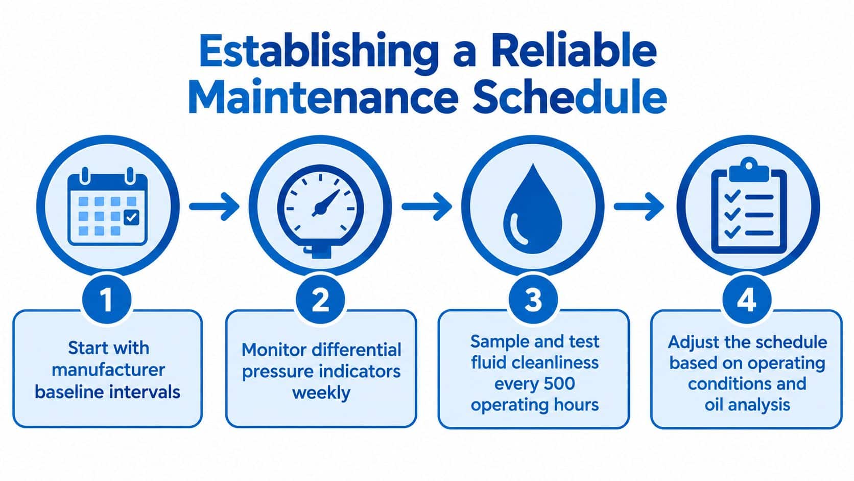
Build the schedule around condition
Use the manufacturer's baseline, then adjust it with evidence:
- Start with the approved interval. Confirm the filter type, element specification, bypass setting and required cleanliness target.
- Watch restriction. Record differential-pressure indicators during routine inspections. A rapid return to the service zone suggests an unresolved contamination source or excessive loading.
- Sample the fluid. Compare particle counts and water content with the equipment's specified target, rather than relying on oil appearance.
- Record every service. Note operating hours, filter location, element condition, oil added or removed, seal condition, debris and the return-to-service checks.
HSE fluid-quality guidance stresses supplier-defined maintenance, contamination prevention and regular flushing where stagnation or microbial growth presents a risk. Its fluid-quality guidance supports treating cleanliness as an ongoing control rather than a one-off wash.
For pressure systems, maintenance planning should also reflect equipment age, use, operating environment and the competence of people carrying out the work. The HSE pressure-systems guidance is relevant when filter servicing forms part of a wider pressure-equipment maintenance programme.
MA Hydraulics Ltd can help source replacement filter elements, cross-reference hard-to-find components, advise on hydraulic filtration and support bespoke power-pack requirements for mobile and industrial machinery. For practical guidance on filter selection, contamination control and safe servicing, contact 01724 279508 today or send a message online.
Contact MA Hydraulics Ltd for correctly specified filter elements, hydraulic component advice and support with bespoke power-pack requirements. Call 01724 279508 today, or send a message through the contact page to discuss a recurring contamination problem or hard-to-find replacement part.
