
The loader's lifting slowly, the excavator's whining, or the factory power pack is getting hot before the shift is properly underway. Someone suggests a new pump, but fitting one before checking the circuit can turn a repair into another breakdown.
The most useful approach to hydraulic pump failure causes is to treat the pump as the last component to condemn, not the first. Start with safe isolation, fluid condition, the suction path and pressure protection. Then measure whether the pump itself has failed.
Symptoms That Point to a Specific Pump Fault
| Symptom | Likely cause | First check |
|---|---|---|
| Whining or chattering noise | Cavitation from restricted suction or aerated oil | Inlet line, suction strainer and fluid level |
| Foam on the reservoir oil | Air entering the suction or return side | Breather, return line and suction joints for air leaks |
| Slow or weak actuators | Internal wear or bypass caused by particles | Oil particle count and case-drain flow |
| Pump running hot | Relief setting too high or sustained overload | Operating pressure logged against the relief setting with a calibrated gauge, with no adjustment |
| Milky or cloudy oil | Water ingress from rain or condensation | Breather, filler cap and seals |
| Metal flakes in the filter | Internal wear already in progress | Filter debris review and wear-metal analysis |
| Erratic or unstable pressure | Stuck valve spool or contamination in valves | Valve cleanliness and pressure readings across the cycle |
| No flow or seizure | Severe contamination, cavitation or dry running | Stop the machine, then inspect suction path and reservoir |
These are diagnostic starting points, not verdicts. A weak cylinder can result from insufficient pump delivery, but oil bypassing through a valve or actuator can produce much the same complaint. Don't order a pump solely because the machine won't lift its normal load.
Pay attention to combinations. A pump running hot alongside a pressure drop can indicate internal bypass, but a relief valve passing oil continuously can also generate heat while reducing useful output. Pressure alone won't distinguish them, so a competent engineer may need flow testing at operating temperature and under a controlled load.
Record the conditions, not just the symptom
Note whether the fault appears at cold start, after warming up, during a particular movement or whenever the engine reaches working speed. Record oil temperature, drive speed and the affected function alongside pressure readings. A description such as “slow only when hot” is more useful than “pump weak”.
Case-drain measurement is useful only on pumps with a suitable drain arrangement, and readings need the manufacturer's limits for comparison. Don't loosen a line to judge leakage by eye.
Practical rule: Test the cheapest explanation first: fluid level, appearance and filter condition. Move to measured pressure and flow before opening the pump.
How to Check a Suspect Pump Safely
A pinhole leak from a hydraulic hose can look like a wet spot until someone runs a hand over it. Hydraulic fluid injected beneath the skin is a medical emergency, and HSE's agriculture machinery fluid guidance treats that injection hazard as the reason to keep hands away from suspected leaks. The pump is usually the last component to condemn. Repeat failures often begin upstream, in dirty fluid, a restricted suction line or a pressure setting that overloads the unit.
Establish safe test boundaries
-
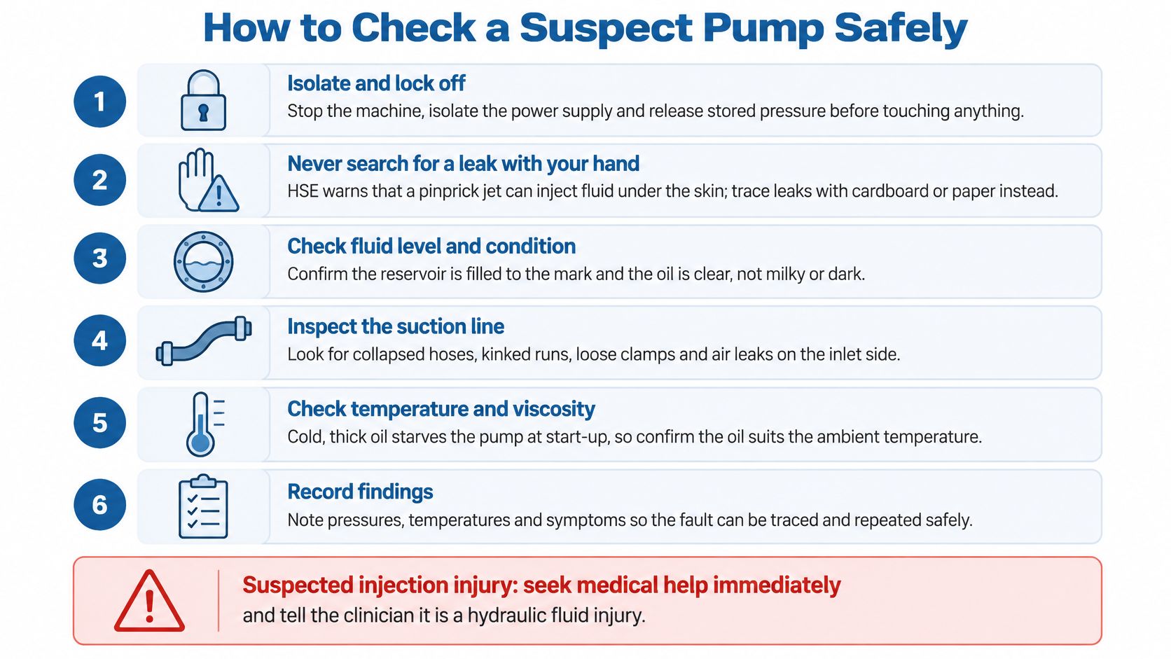
Stop and secure the machine. Severe noise, loss of control, seizure or a suspected pressure leak means stop. Lower attachments where safe, support raised equipment mechanically and prevent unexpected movement.
-
Isolate electrical power and the hydraulic drive. Lock off the supply and prevent engine, PTO or motor restart. A stopped control panel is not proof that the machine cannot move.
-
Release stored pressure. Follow the machine's specified procedure, including accumulators and trapped sections. Confirm zero on an appropriate gauge at the relevant test point. One gauge will not prove every branch is depressurised.
-
Never search with bare hands. Use card or a board only within an approved leak-testing procedure, keeping clear of the suspected jet. Suspected injection injury needs immediate medical attention even when the wound looks insignificant.
-
Check the oil safely. Examine level, colour, smell, foam and milkiness through the sight glass or an approved sample. Do not open a hot or pressurised reservoir.
-
Inspect filtration and breathing. With isolation confirmed, check the suction strainer, return filter and breather. Keep suspicious debris for examination rather than washing away the evidence.
-
Inspect hoses and fittings. Look for abrasion, damaged reinforcement, collapsed sections and insecure connections. Use compatible replacements matched to the original equipment specification, as set out in HSE's pressure-system safety guidance.
-
Record findings and escalate. Relief settings, internal wear and unexplained pressure faults need a competent engineer. Any live testing needs its own controlled procedure, suitable instruments and effective guarding.
The visual checklist reinforces the isolation and inspection sequence.
Never keep running a machine on a suspected fault to see whether it clears.
Contamination and Oil Monitoring That Catches Wear Early
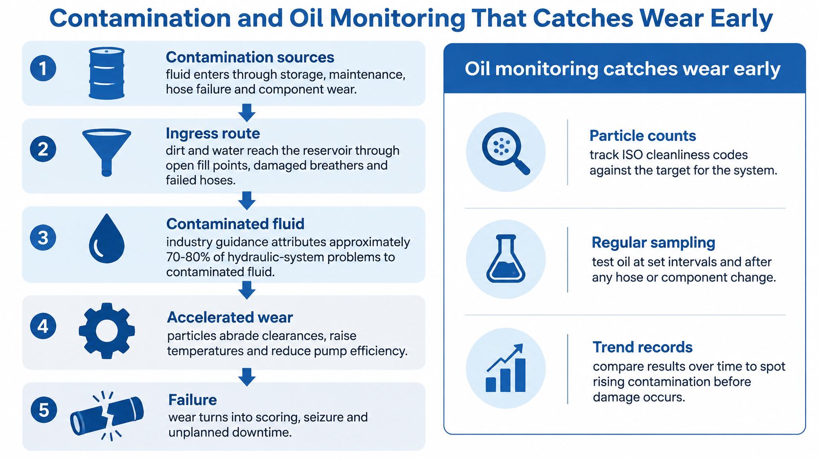
UK industry guidance from MA Hydraulics on fluid cleanliness attributes approximately 70–80% of hydraulic-system problems to contaminated fluid. That's an industry estimate, not a single audited national dataset, but it makes contamination the logical starting point.
Particles entering during storage, maintenance, hose failure or component replacement abrade the pump's close-clearance surfaces. They also obstruct valves and filters, impair lubrication and accelerate seal and bearing deterioration. Water from rainfall, condensation or an insecure filler cap weakens the lubricating film and promotes corrosion.
A replacement pump installed above a dirty reservoir can suffer the same damage as its predecessor. Replacing the visibly failed component doesn't remove debris already circulating through the machine.
The damage path explains why keeping dirt out is more effective than repeatedly changing components.
Build a trend rather than collecting isolated samples
For offshore lifting equipment, HSE guidance recommends filtered reservoir filling, agreed oil-sampling procedures and cleanliness assessment using ISO 4406. Those controls provide a useful model for maintaining agricultural and industrial circuits, while the equipment supplier should determine the actual cleanliness target.
A 1,900-hour study on a 22-tonne hydraulic excavator identified metallic-particulate detection as a reliable real-time indicator of hydraulic-component wear. Clear-looking oil alone therefore isn't enough to confirm good condition.
Use oil analysis to compare particle counts, wear metals and water over time. Rising readings should trigger investigation of filtration, breathers, reservoir cleanliness and relevant case-drain performance.
| Check | Typical frequency | What it reveals | Action if it fails |
|---|---|---|---|
| Fluid level and appearance | Before each shift or daily | Low level, foam or milkiness | Top up through a filter after tracing losses; check breather and seals |
| Filter condition indicator | At each service interval | Blocked filter or bypass | Replace filter and review debris |
| Oil sample for particles and water | At the interval set by the supplier or laboratory | Wear metals, ISO 4406 cleanliness and water content | Clean the circuit and trace the source |
| Breather and filler cap | At each service | Dust and moisture entering the reservoir | Replace the breather and seal the filler |
| Relief valve setting | After repairs or any pressure fault | Over-pressure risk | Set with specialist equipment only |
Treat these as planning checkpoints. Supplier instructions, laboratory advice and operating conditions should determine the maintenance schedule.
Suction, Aeration and Cold-Start Faults That Starve a Pump
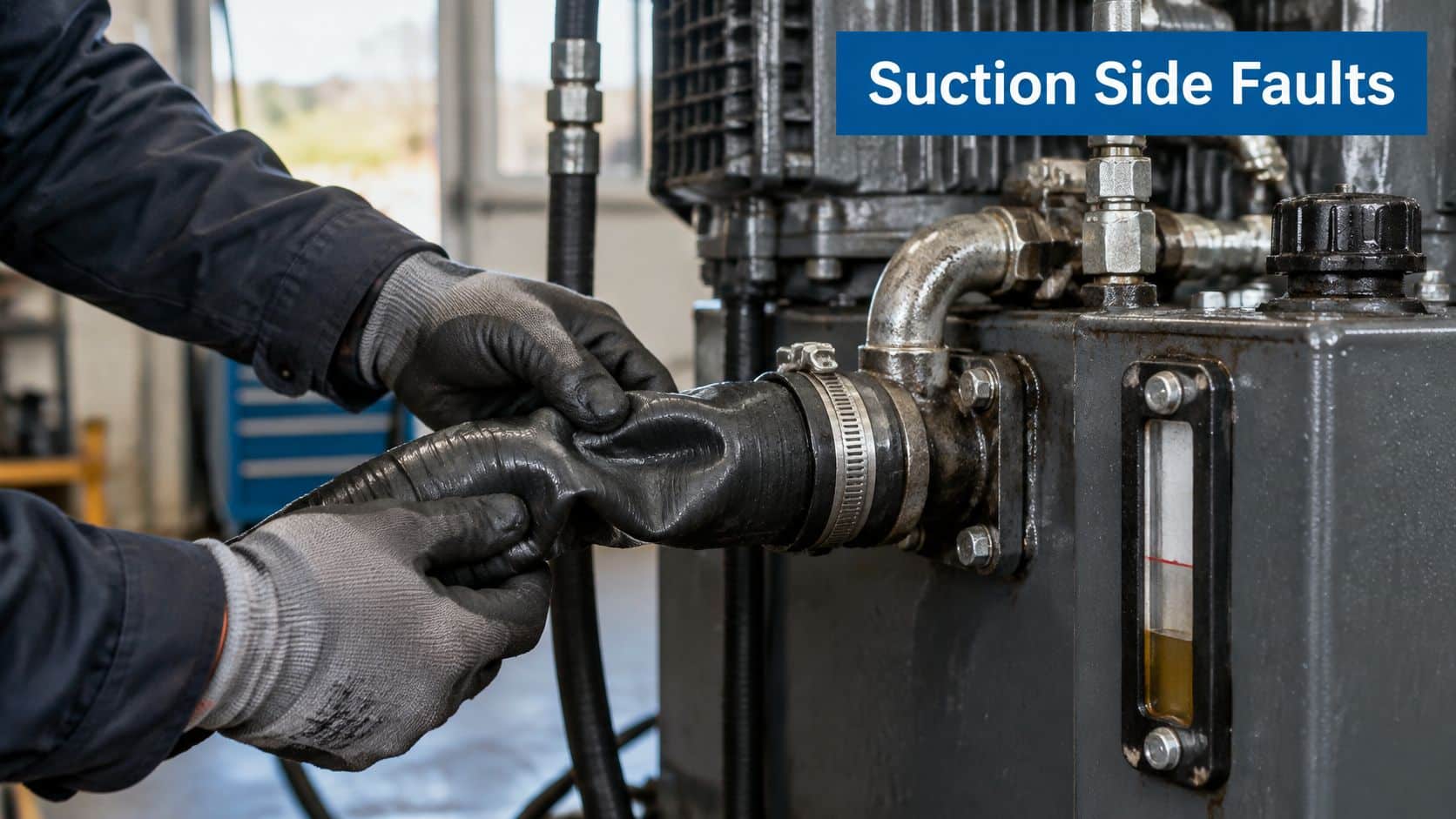
A pump drawing through a restricted inlet is like someone drinking through a kinked straw. The reservoir can be full while the pump still can't receive enough oil. MA Hydraulics' pump guidance identifies undersized suction lines, collapsed hoses, air leaks, excessive cold-start viscosity, incorrect rotation and excessive speed among recurring failure mechanisms.
Inspect the complete hose run, including bends and sections hidden behind guards.
Cavitation and aeration aren't interchangeable. Cavitation involves vapour cavities forming when local pressure falls too low; aeration involves air entering or becoming entrained in the oil. Both can produce noise, unstable delivery and damage, but identifying the inlet restriction or air-entry route matters more than naming the noise.
Follow the cold-start check order
- Check viscosity at the actual starting temperature. Compare the oil's viscosity in mm²/s, also expressed as cSt, against the pump supplier's permitted range. Don't assume the grade alone proves suitability.
- Check reservoir level and inlet restriction. Examine the suction strainer and establish whether a blocked breather is preventing the reservoir from breathing.
- Inspect the suction hose and joints. Look for kinks, internal collapse and loose connections. An inlet joint can admit air without leaving an obvious external oil leak.
- Verify the drive arrangement. Once the inlet checks pass, investigate rotation, engine or PTO speed, coupling condition and alignment.
Our explanation of pump cavitation gives further context for inlet starvation.
The following video provides additional visual context.
Keep separate hydraulic systems separate in your diagnosis. On a road vehicle with clutch-operation symptoms, Daf Marketplace Ltd's master cylinder or worn clutch? guide addresses that different diagnostic question, rather than the working-hydraulics pump.
Over-Pressure and Circuit Faults That Overload a Pump
Turning up pressure to compensate for weak performance is a poor diagnostic shortcut. An incorrectly adjusted or malfunctioning relief valve can expose a sound pump and its connected components to loads they weren't designed to withstand.
In laboratory testing of tracked-vehicle tensioning assemblies, HSE found that pressures above those normally expected could fail new-condition components and warned against adjusting relief valves without specialist setting equipment. That finding concerns a specific assembly, but the maintenance principle is clear: investigate unexplained pressure loss rather than increasing the setting.
Measure the circuit under the fault condition
A competent engineer should use suitable test points and a calibrated gauge or pressure transducer to:
- Confirm protection. Establish the specified relief opening pressure and verify the actual setting using the correct procedure.
- Compare working pressure. Check readings against the manufacturer's limits throughout the affected operating cycle.
- Capture transients. Log pressure spikes that a simple dial reading might miss.
- Locate restrictions. Examine valves, filters, hoses and actuators rather than assuming every pressure fault originates inside the pump.
Our guide to pressure relief valve sizing explains why protection must suit the circuit, not merely fit the available port.
A pressure adjustment can hide a symptom while increasing the load on the component that's already struggling.
Different circuit faults need different remedies. A blocked inlet starves the pump; a sticking actuator or restricted pressure path can force it to work against excessive resistance. Neither is corrected by fitting an identical pump and leaving the circuit untouched.
HSE's pressure-systems guidance calls for maintenance programmes that cover the whole system and account for age, use and operating environment. Apply that whole-system discipline without assuming every hydraulic installation has identical statutory examination requirements.
Repair, Rebuild or Replace the Pump
Make the purchasing decision after establishing the cause and measuring the damage. A restricted inlet doesn't automatically mean the pump is ruined, but correcting the restriction doesn't prove the pump survived either. Confirm delivery and leakage against the manufacturer's criteria.
| Option | When it makes sense | Main trade-off |
|---|---|---|
| Repair the circuit without opening the pump | External fault confirmed and pump performance remains within limits | Avoids unnecessary replacement, but needs convincing test results |
| Specialist rebuild | The design is serviceable and usable core components remain | Retains the existing configuration, subject to parts availability and rebuild cost |
| Replace the pump | Damage is severe, the unit isn’t economically serviceable, or a matched replacement is preferable | Can simplify the repair, but won’t remove the original cause |
Scored housings, worn gear faces, seized shafts and pitted bores need specialist assessment. They don't all carry the same repair decision: component availability, machining limits and the pump's construction determine whether rebuilding is sensible. Don't accept a seal change as a cure for worn internal running surfaces.
Answer the buying questions
- Has the cause been removed? Ask for the confirmed fault, supporting readings and corrective work, not just a description of the damaged pump.
- Does the specification match? Verify displacement, pressure rating, shaft, mounting, ports and rotation. A physically similar unit isn't necessarily interchangeable.
- Is the supply decision sound? Confirm availability, warranty terms and what testing is included. Obtain written quotes from at least two suppliers, with costs stated in GBP.
Following an over-pressure event, include hoses, actuators and pressure protection in the damage assessment. Record the cause, parts fitted and test results in the machine log so future maintenance decisions have a usable history.
Confirm the Fix Before Returning the Pump to Work
A repaired machine earns its return to service through documented checks, not because the new pump sounds quieter unloaded. Prove the original fault has gone: contaminated oil, a starved suction line or a pressure setting that overloaded the pump will destroy a replacement just as quickly. Work through the record and stop at any failed check.
Complete the commissioning record
- Clean the circuit. Flush pipework using an appropriate procedure and clean the reservoir, including accessible sediment traps.
- Renew filtration. Replace filters and breathers with the specified types. Do not substitute elements solely because they fit.
- Fill cleanly. Use the correct oil through a filtered filling system and keep fill connections protected throughout.
- Verify rotation. Check the pump plate and drive direction before starting.
- Confirm displacement and speed. Match the installed pump to the specified engine, motor or PTO operating range.
- Check starting viscosity. Confirm suitability at the actual ambient temperature, not just the warmed-up condition.
- Verify pressure protection. A competent person should set and check the relief opening pressure using specialist equipment and a calibrated gauge.
- Check the mechanical drive. Confirm alignment, coupling condition, mounting security and the specified installation clearances.
- Run under controlled conditions. Follow the manufacturer's priming and start-up procedure, begin at low load, and monitor noise, temperature and pressure stability before applying working load.
If a check fails, stop and investigate. Cleaning, filtration and controlled filling are not optional after a contamination failure. Running harder will not compensate for incomplete commissioning.
Keep a signed record of readings, instruments and acceptance criteria. MA Hydraulics Ltd can source equipment from most major manufacturers to help match the replacement to the machine.
At MA Hydraulics Ltd, we support product sourcing, system components, custom power-pack assembly and technical advice. Get in touch by phone or email, or send us a message with the pump identification, machine details and diagnostic findings.
