

You've changed the return filter, topped up the reservoir and put the machine back to work. The indicator is climbing again, the pump sounds different, and the oil still looks clean. Before ordering another element, check how contamination is entering the pack, not just where you're catching it.
A hydraulic power pack oil filter is part of a contamination-control system. Filling equipment, reservoir breathers, seals, operating temperature and maintenance practices all affect what reaches the pump and valves. The installed filter should be your last line of defence, not your excuse to pour unfiltered oil into the tank.
Where the Oil Filter Sits in a Power Pack
Think of reservoir filtration as the pack's kidney function. Oil circulates through different paths, and each filtration position has a different job. The reservoir itself stores oil and allows some settling, but it doesn't replace effective filtration.
A pack can have up to five filtration points, although many installations use fewer. Trace the pipework and identify what's fitted before choosing a replacement.
Filter positions in a hydraulic power pack
| Position | Typical rating | What it protects | Service |
|---|---|---|---|
| Suction strainer | 100-150 µm | Pump inlet from large debris | Clean at each major service |
| Pressure-line filter | 3-10 µm | Proportional and servo valves | Replace on pressure-drop indication |
| Return-line filter | 10 µm absolute | Tank and returning circuit | Replace on indicator or scheduled hours |
| Offline (kidney-loop) filter | 3-5 µm | Whole oil volume over time | Replace at cartridge hours |
| Reservoir breather | 3 µm (air) | Tank from airborne dust and moisture | Replace when clogged or wet |
These are starting specifications, not permission to substitute an element without checking its datasheet. A micron rating alone doesn't establish efficiency, pressure capability or suitability for the oil.
Follow the oil path
The suction strainer sits before the pump. Its coarse mesh intercepts larger debris, but excessive inlet restriction can starve the pump. Fitting finer suction media without checking the inlet conditions is a poor way to improve cleanliness.
The pressure-line filter sits downstream of the pump and upstream of sensitive components. Its housing must withstand pressure at that location, while its element must tolerate the specified differential pressure.
The return-line filter captures contamination before returning oil reaches the reservoir. It's often the element the service engineer changes routinely, which makes the other filtration points easy to overlook. Check the hydraulic filter mounting arrangement as well as the cartridge, including flow direction, indicator position and access for removal.
An offline filter uses a separate circulation loop to clean the reservoir contents over time. It supplements circuit filtration rather than protecting a valve immediately downstream of a failing pump.
Finally, the breather filters incoming air as the reservoir level changes. Particle filtration and moisture control aren't interchangeable, so specify moisture-removing capability where the environment requires it.
Before ordering: Count the filtration points on your own pack and identify which component each one protects.
Why Cleanliness Targets Set the Filter Rating
Clean-looking oil isn't necessarily clean enough for a hydraulic system. Fine particles can pass unnoticed during visual inspection while damaging the working surfaces inside pumps and precision valves.
As explained in MA Hydraulics' hydraulic oil filtration guidance, ISO 4406 expresses particle contamination using three size bands, particles larger than 4, 6 and 14 µm, producing a code such as 18/16/13. Each position describes its own particle-size band, not a filter rating.
For example, oil coded 18/16/13 contains fewer particles in the corresponding bands than oil coded 19/17/14. A lower code means cleaner oil, but the acceptable target comes from the installed components, not from a general preference for lower numbers.
Typical ISO 4406 cleanliness targets by component
| Component | Typical ISO 4406 target | Filter rating implication |
|---|---|---|
| Gear pump | 18/16/13 to 19/17/14 | 10 µm return filter usually adequate |
| Vane pump | 17/15/12 | 5-10 µm return filter with offline filtration |
| Piston pump | 16/14/11 | 3-5 µm pressure or offline filtration |
| Proportional or servo valve | 15/13/10 or cleaner | 3 µm pressure filter plus offline loop |
Treat these as typical selection starting points, not guaranteed outcomes. The pump and valve manufacturers' cleanliness requirements take precedence, and the proposed filtration arrangement must demonstrate that it can achieve them.
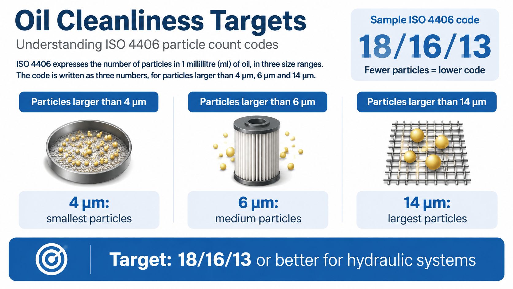
The general target illustrated above isn't suitable for every component. Use the component-specific table and the actual equipment datasheets when setting the acceptance limit.
Establish a baseline you can compare
Take a representative sample when commissioning a pack or returning it to service after substantial maintenance. Use a suitable sampling point and consistent sampling conditions, then record the result alongside oil temperature, operating condition and recent work.
Compare subsequent samples against that baseline. A rising count warrants investigation, particularly after opening pipework, replacing hoses or repairing a component. Sampling technique matters: a dirty bottle or contaminated sampling connection can lead you towards the wrong diagnosis.
Use the ISO cleanliness code guide to interpret the result rather than judging the oil by colour. Also record differential pressure, because an overloaded element may allow oil through its bypass instead of through the filter media.
The most contamination-sensitive component sets the cleanliness target. The pump type alone doesn't decide the filter.
How to Choose a Filter for Your Power Pack
Start with the component that needs the cleanest oil. A gear-pump power pack supplying a proportional valve needs a filtration strategy that protects the valve, not one that keeps the pump running.
A filter that fits the existing head can still be wrong for the application. Match its efficiency, capacity, flow performance and pressure capability before worrying about the thread.
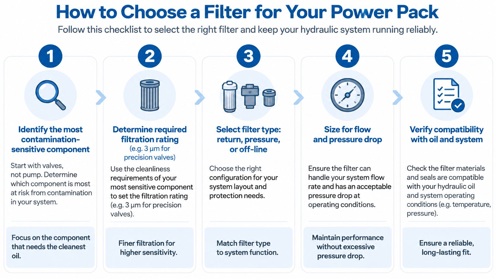
Check the specification in this order
-
Set the particle rating and beta ratio. Specify the required absolute rating together with the manufacturer's efficiency data, because two elements carrying the same micron description may capture particles differently. The beta ratio compares upstream and downstream particle counts at a stated particle size.
-
Check dirt-holding capacity. Dusty agricultural work, frequent hose connections and maintenance-intensive machinery can load an element faster than a sealed indoor installation. More suitable media area can provide useful service capacity without accepting excessive pressure drop.
-
Size for maximum flow. Use the highest flow through the filter's actual position, not just nominal pump delivery. Cylinder return flow can exceed pump flow, so check actuator geometry and simultaneous movements before selecting a return filter.
-
Confirm pressure capability. For a pressure-line installation, select the housing against maximum system pressure, relief setting and anticipated surges. A return housing needs checking against return-line transients, while the element itself needs adequate collapse resistance.
-
Verify the bypass setting. Around 2 bar is a typical return-filter starting point, not a universal setting. Check the specified valve, clean-element pressure-drop curve and cold-oil viscosity so normal operation doesn't repeatedly send oil around the media.
-
Choose connections and compatibility last. Confirm port size, thread, seals, fluid compatibility and service clearance after the filtration duties are established. An adaptor cannot correct an undersized housing or unsuitable element.
Check the complete housing-and-element assembly, not a cartridge in isolation. An element with the desired rating may still be unsuitable for the housing's bypass arrangement or the pack's operating fluid.
Make the specification maintainable
The HSE's guidance on maintaining fluid quality advises checking strainers and filters regularly for blockage. Fit an accessible indicator and make its reading part of the maintenance record.
At MA Hydraulics, we stock OMT Group filters and offer filler breathers, level gauges, power transmissions, bell housings, couplings, gaskets, feet and accessories.
Record the element part number, absolute rating, beta ratio and bypass setting on the maintenance label. That prevents the next replacement being selected solely because its dimensions match.
Keeping New Oil Clean During Filling and Storage
A new filter doesn't guarantee clean oil. If you pour contaminated oil into the reservoir, you've introduced a problem before the pack has completed its first working cycle.
MA Hydraulics' filter selection guide explains why oil transfer, storage and reservoir protection belong in the filtration plan. New oil from a drum or bulk supply shouldn't be assumed to meet the machine's cleanliness target.
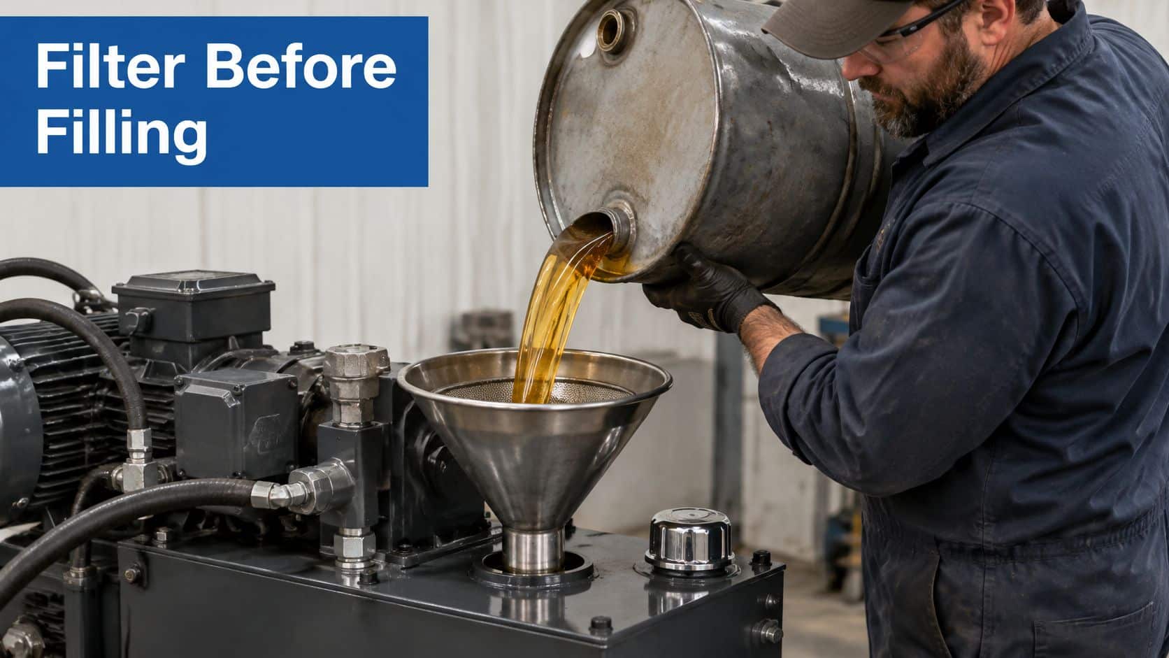
A filler screen catches coarse debris. It isn't a substitute for a transfer filter selected to achieve the required particle cleanliness.
- Use dedicated transfer equipment. Keep hydraulic-oil containers, hoses and connections sealed and separate from equipment used for other fluids.
- Pre-filter before filling. A 3 µm transfer unit, for example, may suit a demanding cleanliness target, provided its capacity and fluid compatibility are appropriate.
- Protect the filler opening. Clean around the cap before opening it and close the reservoir between filling operations.
- Check the breather. Replace damaged or contaminated equipment rather than transferring clean oil into a tank that immediately draws in dirty air.
- Record the batch. Log the oil grade, source and filling date so an abnormal sample can be traced to a transfer operation.
Keep workshop products out of the reservoir
Good housekeeping includes looking after maintenance tools, but tool-protection oils don't belong in hydraulic fluid. Evo Dyne Products' resource on oiling wrenches and shop tools is useful context for keeping tools protected separately from dedicated oil-transfer equipment.
On mobile and agricultural machinery, inspect damaged rod wipers, exposed connections and neglected breathers. Dust and wet operating conditions create ingress routes that a fresh return element cannot repair.
Practical rule: Prevent contamination at the filling point rather than paying to remove it after it enters the circuit.
Don't pursue finer filtration by restricting the pump inlet. Check cold-start viscosity, transfer flow and suction conditions, and use hydraulic oil filtration practices that protect the whole system. Take a particle count after refilling to establish the pack's return-to-service baseline.
Service Intervals for Filters, Oil and Breathers
Check and replacement intervals by duty
| Duty | Check differential pressure | Oil sample | Replace the element when |
|---|---|---|---|
| Indoor industrial, clean | Monthly | Every 2,000 hours | Indicator reaches red or bypass opens |
| Mobile or agricultural, dusty | Weekly | Every 500 hours | Indicator reaches red or sampling shows rising particles |
| Washdown or outdoor, wet | Weekly | Every 500 hours with water test | Water found in sample or indicator reaches red |
Use this as a provisional maintenance schedule, subject to the equipment manufacturer's instructions and the pack's condition history. Check indications more frequently during commissioning, after repairs or when contamination is suspected.
A green indication normally means differential pressure is below the warning threshold; it doesn't prove the oil is clean. A rising reading suggests increasing restriction, while red or bypass operation requires prompt investigation. Interpret colour indicators using the specific filter manufacturer's instructions.
Separate cold-start behaviour from a loaded element
Cold, viscous oil can produce a temporary high differential pressure. An indication that persists at operating temperature needs attention, and repeated cold-start bypassing warrants a sizing and viscosity review rather than being dismissed as normal.
A UK university field investigation of excavator hydraulics reported scheduled return-filter changes at 500 operating hours, with particulate trends changing across filter periods. That supports monitoring element condition and oil cleanliness together, not treating a scheduled interval as universally correct.
Replace the element without introducing more dirt
- Isolate safely. A competent person isolates and locks out the drive, secures supported loads and releases stored hydraulic energy, including accumulators. Confirm depressurisation using the designated test points; a single zero-reading gauge doesn't prove every trapped section is safe.
- Contain the oil. Clean the housing exterior, position a drain tray and remove the bowl according to its service instructions.
- Inspect the removed element. Bag it for examination and look for metallic material before arranging appropriate disposal.
- Fit the correct replacement. Install the specified element and new seal, then tighten the bowl to the housing manufacturer's torque.
- Verify operation. Refill with pre-filtered oil where needed, restore the system safely, check for leaks and confirm normal indication at operating temperature.
Outdoor storage, washdown and condensation also require water testing. Water can accelerate corrosion, weaken the lubricating film and deplete additives even when the particle code is acceptable.
Finding water calls for ingress correction and an appropriate oil-treatment or replacement plan. An ordinary particulate element won't remove dissolved water, and changing it alone won't solve the problem. Keep breathers protected and use competent personnel working under safe isolation and depressurisation procedures throughout.
Signs of a Blocked or Failing Filter
A red indicator or open bypass is the clearest warning, but it doesn't identify the cause by itself. Establish whether the oil is cold, the element is loaded or the assembly is undersized before fitting another cartridge.
Symptoms, causes and fixes
| Symptom | Likely cause | Fix |
|---|---|---|
| Indicator red or bypass open | Blocked element or cold oil | Check at operating temperature and change a loaded element |
| Whining pump, slow actuators | Restricted suction strainer | Clean strainer and check oil level and viscosity |
| Hot oil or foaming | Air or water ingress, among other causes | Check breather, filler seal and water content |
| Cloudy or milky oil | Suspected water in the reservoir | Sample for water, correct ingress and drain contaminated oil as appropriate |
| Metallic debris on element | Suspected pump or valve wear | Stop, trace the source and don’t simply replace the filter |
Diagnose the location, not just the noise
A whining pump with sluggish actuators directs attention towards the inlet. Check the suction strainer, oil level, inlet connections and oil grade before blaming the return filter. An inlet air leak can occur without leaving an obvious external oil leak.
Hot oil has several possible causes, including excessive throttling, cooling faults and internal leakage. Foaming makes air ingress particularly important to investigate, but neither symptom proves a filtration fault. Check the operating conditions alongside the oil sample.
Cloudy or milky oil warrants prompt water testing, although entrained air can also affect appearance. Don't drain and refill repeatedly without finding the entry point. Inspect the breather, filler seal and any water-cooled equipment connected to the oil circuit.
Treat metal as a component warning
Visible metallic material deserves more than an element change. Stop the pack safely, retain the element and sample, and investigate whether a pump, valve or another lubricated component is shedding material.
Cutting open an element requires suitable equipment and care to avoid adding debris that confuses the diagnosis. Record what you find, including its appearance and distribution, and use laboratory analysis when the source isn't clear.
A filter that repeatedly blocks inside its established service interval is evidence of an unresolved contamination source, abnormal wear or a sizing problem.
An accessible element replacement and warm-running check may fit into a day's maintenance. Tracing intermittent ingress may require a week of inspections and sampling across actual operating conditions; these are planning examples, not promised repair times.
Return the machine to work on evidence, not because the indicator has reset. Confirm acceptable operation and investigate any continuing deterioration in the sample results.
What to Send When You Need a Filter
Send the details that determine the element's job, not just a photograph of its thread. A readable housing label and current element number help, but they don't establish whether the existing specification is correct.
Have these details ready:
- Operating duty: Indoor industrial, mobile, agricultural or washdown, including cold starts and contamination exposure.
- Hydraulic conditions: Maximum working pressure, relief setting and maximum flow through the filter position.
- Installed equipment: Pump type and any proportional or servo valves.
- Filter specification: Element part number, micron rating, beta ratio and bypass setting.
- Condition evidence: Latest ISO cleanliness result, water findings, repeated blockage or metallic debris.
For maintenance teams improving their records, SIX ERP's discussion of turning spare parts data into advantage provides useful context for retaining failure and replacement information alongside part numbers.
Our team in Scunthorpe can help with component selection, cross-referencing and technical advice. Flag milky oil, metal or unusually short element life before another replacement is selected.
Ask for the quotation in GBP, and retain the agreed specification on the maintenance label. A correct part number is valuable; a part number backed by its rating and operating conditions is much harder to substitute incorrectly.
MA Hydraulics Ltd offers OMT filtration components, Bespoke Built Power Packs and Hydronit Mini Power Packs assembled to suit customer applications, alongside bespoke industrial power packs manufactured in house up to 11 kW. Visit MA Hydraulics Ltd for component and power-pack support, and send the filter specification and operating details so we can help identify a suitable replacement. Phone 01724 279508 today, or send us a message to discuss your pack's filtration needs.
