
UK consumption of hydraulic pumps classed as gear, vane and other rotary positive-displacement fell 33.3% year on year to about 1.2 million units in 2024, against domestic production of roughly 751,000 units, according to the IndexBox UK market overview. Consumption had peaked at 5.3 million units in 2019, which tells you how violently demand swings in a category that includes every tandem gear pump on a spreader, a refuse body or a telehandler.
That volatility decides how these pumps get bought. When machines are being built in volume, the specification drives supply. When they aren't, replacement availability and cross-referencing do, and the difference between a pump that fits and one that nearly fits lands on a service engineer at six in the morning.
A tandem gear pump is rarely the whole problem or the whole solution. It's a system decision, and it needs to be treated as one: what the arrangement is, how two gear sets share a single drive, what real UK machinery flows look like, when a tandem is the wrong answer altogether, how to size it against the drive, and how to commission it without wrecking a PTO.
Tandem Gear Pump Configurations at a Glance
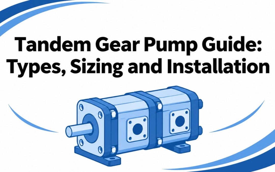
A tandem gear pump is two gear pump sections on one drive shaft, each with its own inlet and outlet, so a single engine, electric motor or power take-off feeds two hydraulic circuits. The sections turn at the same speed, but they don't have to be the same size. A common pairing is a large section for a high-flow implement circuit and a small section for steering, clamping, brake release or a fan drive.
| Configuration | Drive arrangement | Sections | Typical use |
|---|---|---|---|
| Tandem pump in a common housing | One drive shaft through both gear sets | Two gear sets, one body | Compact dual-circuit supply on mobile plant |
| Two pumps coupled in line | Coupling between two pump bodies | Two independent pump bodies | Retrofit where two standard units are fitted in line |
| Gearbox-mounted tandem | Power take-off drives both pumps | Two sections with separate outlets | Agricultural and municipal machinery |
Each configuration changes the mechanical question rather than the hydraulic one. A common-housing unit is a single item to align and one set of ports to pipe. Two coupled pumps let you build an assembly from stock units, which is often the only practical route on an older machine. A gearbox-mounted arrangement puts the assembly's weight somewhere other than the PTO shaft, and that distinction matters more than most catalogue pages admit.
The product class is long established in the UK. The British Fluid Power Association estimates the UK fluid-power market at approximately £1.1 billion in 2024, with hydraulics representing about 80% of it. That is a very large installed base of gear pumps in agriculture, waste handling, construction and factory maintenance, and it runs on replacement parts as much as new builds.
Before you compare a single flow figure, record three details:
- Drive type and interface. Splined shaft, keyed shaft, SAE flange or direct gearbox mounting decides which pump families are available at all, and how much bracketry the job needs.
- Shaft rotation. A unidirectional pump run the wrong way won't pump. A reversible unit is a different part number, often a different price and sometimes a different lead time.
- Circuit split. Whether each outlet feeds its own circuit or the two combine determines whether you need separate relief settings, check valves, isolation and independent filtration.
Record those three before you open a catalogue. They eliminate more wrong pumps than any flow calculation.
How Two Gear Sets Share One Drive
Think of a bicycle crank with two chainrings on the same axle. One turn of the pedals turns both rings, but each chain drives something different. A tandem pump behaves the same way: the input shaft passes through both gear sets, so one revolution of the drive produces one revolution of each section, and each section pushes oil only into its own outlet port.
Inside the casing, oil enters the inlet port on the suction side, fills the spaces between the teeth and the casing wall, is carried around the outside of the gear pair, and is forced out where the teeth come back into mesh. The sections are joined mechanically but not hydraulically. Isolation comes from separate outlets, separate relief valves and separate return paths, which is why the circuit design, not the pump body, decides whether the two functions interfere with each other.

Flow follows speed and displacement, and nothing else: litres per minute = displacement in cm³ per revolution × rpm ÷ 1000. A 40 cm³/rev section turning at 2,000 rpm gives a theoretical 80 L/min. If the second section is 22 cm³/rev on the same shaft, it delivers a theoretical 44 L/min at the same instant, so the pair moves 124 L/min before any losses. Neither figure changes unless speed or displacement changes.
Three limits govern what that assembly can do:
- Each section carries its own pressure rating. Continuous and peak limits are set per section and can differ in a mixed-displacement unit, so check both rather than assuming the higher figure applies to the whole body.
- The shared shaft sees the sum of both loads. Torque adds even when the circuits are separate. A small section working against a high pressure can dominate the driveline calculation while contributing very little flow.
- Delivery is always below the theoretical number. Internal leakage past the gears and side plates rises with pressure, oil temperature and wear, which is why a tired pump loses speed under load long before it drips on the floor.
The pump sets the flow. The load sets the pressure. That one distinction explains most tandem-pump trouble, because two circuits on one shaft stay joined mechanically even when they're completely separate hydraulically.
The single-section behaviour behind that leakage is set out in this guide to how a gear pump works, and it applies unchanged to each half of a tandem.
Flow Figures from UK Agricultural and Mobile Machinery
Published UK machinery specifications show why builders use multi-section layouts instead of one large pump. The figures below come from AAFM machinery specifications covering machines working demanding implements.
| Published specification | Pump arrangement | Flow rate | Engine speed |
|---|---|---|---|
| Single-pump agricultural system | Single pump | 200 L/min | Not stated |
| Same system with optional dual pump | Dual pump | 400 L/min | Not stated |
| Standard system | Single pump | 216 L/min | Not stated |
| Optional twin-flow system | Twin-flow | 428 L/min | Not stated |
| Triple-pump configuration | Triple pump | Up to 636 L/min | Not stated |
| Multi-section system at 1,650 rpm | Multi-pump | 205 L/min | 1,650 rpm |
| Multi-section system at 1,850 rpm | Multi-pump | 270 L/min | 1,850 rpm |
| Optional dual closed-centre pump | Dual closed-centre | 340 or 400 L/min | Not stated |
Read the smallest numbers first. A single pump giving 200 litres per minute rises to 400 litres per minute when the optional dual-pump arrangement is specified. Nothing about the implement changed. The second section exists purely to add flow to a circuit that was already at its limit, which is the cleanest possible argument for a tandem layout.
The next machine shows the same logic at a smaller step: 216 litres per minute standard, 428 litres per minute with the optional twin-flow system. That's roughly double the delivery from the same engine bay, which is what a second section buys when the implement, not the engine, is the constraint. At the top end, a triple-pump configuration is published at up to 636 litres per minute.
Why engine speed changes the answer
One specification gives 205 litres per minute at 1,650 rpm and 270 litres per minute at 1,850 rpm. Straight speed scaling from 1,650 to 1,850 rpm would land near 230 L/min, so the published 270 points to a different displacement or a different setting rather than revs alone. Compare flows at the speed your machine works at, not at the rpm that flatters the brochure.
The optional dual closed-centre pump is listed at 340 or 400 L/min, and that pairing is worth studying because closed-centre circuits behave differently from open-centre ones when two sections share a drive. Standby pressure, not flow, sets the heat load in that arrangement.
What the figures don't tell you
These are machine specifications, not ratings for one universal tandem gear pump. They don't state operating pressure, duty cycle or fluid condition. They also don't say how the flow splits between steering, implements and attachments on a municipal or waste machine that has to power all three at once. Match the arrangement, the flow and the engine speed to your own machine, then check pressure and duty at that speed.
When a Tandem Pump Is the Wrong Choice
Combining two sections isn't automatically the better answer, whatever the product pages imply. When both circuits work at similar pressures and run together, a tandem is efficient and hard to beat on packaging. When one circuit holds high pressure for long periods and the other idles at low pressure, the low-pressure section throttles its surplus across a relief valve or restrictor and that surplus leaves the system as heat in the oil.
| Criterion | Tandem gear pump | Separate pumps | Variable-displacement pump |
|---|---|---|---|
| Packaging and installation | Compact, one drive point | Larger, two drive points | Compact, one drive point |
| Efficiency with mismatched circuit pressures | Lower; surplus power becomes heat | Higher; each pump matched to its circuit | Higher; flow follows demand |
| Heat generation at part load | High where one section throttles | Lower | Lower |
| Maintenance access | One unit to service | Two units to service | Single unit, more control components |
| Control of each circuit | Fixed by each section’s displacement | Independent | Set by control system |
The heat is the part buyers underestimate. A section sized for a peak that happens twice a shift spends the rest of the day pushing oil over a relief valve, and the reservoir and cooler pay for it. On a machine with limited oil volume and a radiator already fighting engine heat, that's a genuine reliability problem rather than a rounding error.
UK fluid-power standards work addresses the same question in formal terms. PD ISO/TR 22164:2020, listed in the BFPA standards work on systems and accumulators, covers optimisation of hydraulic-system energy efficiency, which is a structured way of asking whether your circuit is generating heat it doesn't need. The same standards community keeps pushing condition monitoring of oil cleanliness, filter condition, leakage and temperature rather than fixed replacement intervals, because a pump's real service life depends on the oil it lives in.
Answer these before you commit:
- What share of operating time does each section run? A second section used twice a day rarely justifies the extra shaft, seal and bearing risk.
- What does the pressure-flow profile look like over a shift? Two circuits at 180 bar behave very differently from one at 250 bar and one at 40 bar.
- Where is unused flow throttled? Relief valves, restrictors and flow-control valves all convert surplus into heat in the same oil.
- How much heat must the reservoir or cooler reject? If nobody has calculated it, the answer is usually "more than the cooler can manage in August".
- Does the second section earn its place? Compare it against a separate electric pump, a power pack, load sensing or a variable-displacement unit.
A cheaper pump that adds heat is an expensive pump. Judge the decision on energy, noise, temperature, service access and downtime, not purchase price.
A tandem gear pump still wins in three situations: a compact retrofit where there's no second drive point, two circuits that run together at similar pressures, and machines where the drive interface is the scarcest resource on the whole installation.
Sizing Two Circuits Without Overloading the Drive
Sizing starts with the flow each circuit needs at working speed, then the pressures it works against, then the torque the drive must absorb. Doing it in that order stops you buying a pump that meets a flow target and destroys a PTO.
- Flow per section at rated speed. Calculate it from displacement and the rpm your engine or motor holds under load. A pump that makes the number at 2,500 rpm may be well short at 1,800 rpm.
- Working and peak pressure for each circuit. These set the section ratings, the relief settings and the heat rejection calculation, and a peak that lasts half a second still loads the shaft.
- Duty share per section. The proportion of running hours each section works decides whether the second one is earning its keep or just adding seal and bearing risk.
- Group size and displacement. Common gear pump ranges run from Group 0 to Group 3, and the largest displacement available in each group sets the torque you have to absorb at the drive.
- Shaft rotation and drive interface. Splined, keyed or flange mounting, and clockwise or anticlockwise rotation, decide fitment before performance ever comes into it.
- Mounting and overhung load. The weight of the assembly and its distance from the bearing decide whether a support bracket is mandatory.
Oversizing the second section is the most common error in specifications. It looks like headroom on paper and turns into a hot, noisy machine in service, because the surplus flow has to go somewhere and that somewhere is nearly always a relief valve.
Practical rule: size each section to the flow it needs at working speed, then add the torque of both sections at their own working pressures. If the total sits close to the drive's continuous rating, you've sized it, not over-sized it.
Run the arithmetic with the method in these flow rate calculations before you fix a displacement. Then write down, for each section: flow at working speed, working and peak pressure, share of operating time, required group size and displacement, shaft rotation, and the mounting arrangement. Add the combined input torque and the drive's published limit, and you have a sheet any supplier can quote from without guessing.
How to Install and Commission a Tandem Pump Safely
Sequence matters as much as component choice, and the mechanical checks come before the hydraulic ones because a correctly sized pump that's badly supported still fails. The process below covers the checks that decide whether the assembly survives real mobile-machine duty.
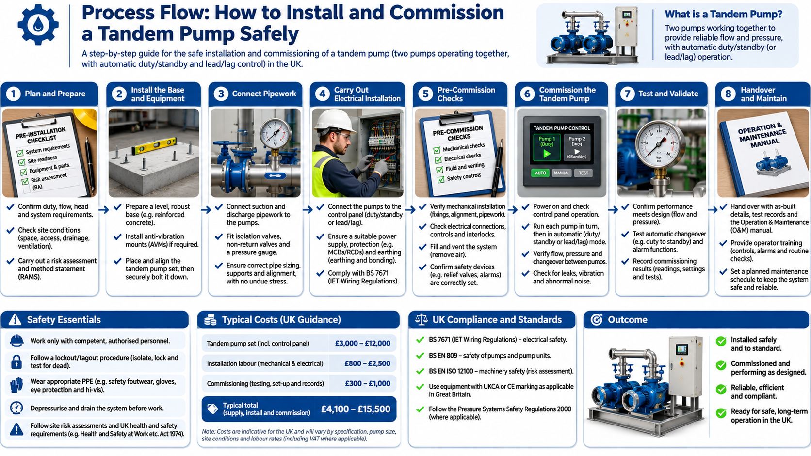
- Check the drive rating against the combined input torque. Parker's tandem pump installation guidance specifies a maximum transmitted tandem torque of 720 Nm for its stated pump range, which shows the order of magnitude such a driveline is designed for. Use your own pump's limit, and remember both sections add torque at the shared shaft. Exceeding it twists shafts and overloads bearings before anything visible fails.
- Compare the assembly weight with the PTO's permissible bending moment. The same guidance warns that a tandem assembly's weight can normally exceed what the PTO is allowed to carry, so the unit may need a gearbox-mounted support bracket instead of hanging off the vehicle chassis. Carrying that load on the PTO bearing shortens seal life and misaligns the coupling.
- Fill both pump bodies and purge air from each section before start-up. Running dry scores the gear faces and side plates within seconds, and a scored pump never recovers its volumetric efficiency. Prime at the inlet, not by cranking the engine.
- Set the standby pressures about 5 bar apart. Parker recommends a 5-bar difference between the two sections' standby settings, and the reason is practical: equal settings make the sections fight each other at start-up and produce hunting and noise. This is why "connect both outlets and run" is unsafe advice.
- Protect each circuit separately. Independent relief valves and check valves stop one circuit back-feeding the other and stop a dead-headed function from loading the shared shaft. Set reliefs at or below each section's rating.
- Start at low speed and verify each section on its own. Check standby pressure, peak pressure, oil temperature and noise for one section at a time so you know which half a fault belongs to. A combined test tells you there's a problem, not where it is.
- Isolate the machine and release stored pressure before any inspection. HSE stresses risk management for hydraulic power supplies, safe isolation and stored energy, and warns that fluid-injection injuries can require major surgery or amputation. Never hunt a leak with a gloved hand.
What good commissioning looks like: no air noise from either section, stable pressure at both outlets when the function is held, and oil temperature settling inside the maker's range at working load.
Follow the torque figures and port orientation in these installation guidelines alongside the pump maker's sheet.
Diagnosis after commissioning
If one section shows low flow, check the inlet line for air and the suction strainer for restriction before you condemn the pump. If both sections are noisy together, suspect cavitation from a starved inlet, which is a plumbing fault rather than a pump fault. If the oil runs hot, look at whether one circuit is throttling surplus flow across its relief at working pressure. If a shaft or seal fails early, recheck the PTO bending moment and bracket alignment before fitting another pump, because the replacement will fail the same way.
Confirm the Specification and Get in Touch
Run the completed sheet one final time before you order. Check that each circuit's flow is set at working speed rather than the lowest catalogue figure, that working pressure, peak pressure and duty-cycle share are recorded for both sections, and that the drive torque and PTO limit are confirmed against the pump you've chosen. Confirm shaft rotation and mounting match the machine, not the drawing.
Ask the awkward question as well. Would one of the alternative architectures serve this duty better? A separate electric pump, a variable-displacement unit or a power pack may cost more at the counter and less over five years, particularly where the two circuits run at very different pressures. Deciding on lifecycle cost and service access rather than headline flow is the difference between a machine that works and a machine that's always in the workshop.
For readers keeping mixed fleets on the road, a truck and trailer service catalog is a useful reminder of how body hydraulics and vehicle systems get scheduled into the same downtime window, which is usually when a tandem pump gets replaced.
Send the completed duty data to MA Hydraulics Ltd in Scunthorpe for cross-referencing, alternative pumps and assembly support. We stock Vivoil unidirectional and reversible gear pumps in Group 0, Group 1, Group 2 and Group 3, and we can match a tandem assembly to your drive's torque and flow. Phone 01724 279508 today, or send your specification through our contact page.
A tandem gear pump is only as good as the sizing and commissioning behind it, and that's where MA Hydraulics Ltd does the useful work. We supply Vivoil gear pumps in Groups 0 to 3, multiple-pump assemblies and alternatives to Parker and German-specification pumps, backed by application advice on torque, flow and drive limits. Send the completed specification sheet to our team in Scunthorpe and we'll cross-reference it, or visit MA Hydraulics Ltd to see the full range of pumps, valves, gearboxes and power packs.
