A lot of engineers only start looking seriously at proportional valve control when a machine begins to show its limits. The cylinder bangs into end of stroke. A grab swings too hard. A conveyor lift overshoots. The operator compensates, but only up to a point. After that, you're fighting the circuit instead of controlling it.
That's where proportional control earns its place. It gives you a usable middle ground between crude on/off movement and the cost and sensitivity that often come with servo hardware. In UK mobile plant, agriculture, materials handling, and general industrial equipment, that middle ground is usually where the practical answer sits.
The Need for Precision in Hydraulic Control
A basic directional valve does one job well. It sends oil one way or the other. If the machine only needs a simple extend and retract, that's often enough. But once the load changes, the operator needs a soft approach, or the machine has to handle product rather than just move steel, on/off control starts to show its weaknesses.
A common example is a boom, clamp, or feed function that moves acceptably when empty and badly when loaded. The same valve still works, but the machine no longer behaves properly. You get shock loading, poor repeatability, and a control feel that operators describe as twitchy or harsh.
Why the old approach stops working
Modern hydraulic equipment expects more than movement. It needs controlled acceleration, stable speed, and smoother deceleration. That matters on a farm machine, a loader, a press, or an injection moulding line. If you've ever looked at a machine specification sheet such as View Synergy 800 230 specifications, you can see how much machine performance depends on controlled and repeatable hydraulic motion, not just raw force.
The underlying idea isn't new. The control-valve lineage goes back to Roman bronze plug cocks and James Watt's moving-stem automatic valve in the late eighteenth century. Modern proportional control emerged later, through mid-20th-century research into variable control of hydraulic and pneumatic actuators, as outlined in this history of control valves.
Proportional technology became commercially useful when hydraulic systems moved beyond simple open or shut behaviour and started delivering continuous adjustment.
Where proportional control fits
In practical terms, proportional valve control sits between a standard directional valve and a servo valve. That's why it turns up so often in UK machinery. You get finer control of flow or pressure without building an ultra-sensitive servo system around every function.
For most site equipment, that balance is what matters. The machine doesn't need laboratory-grade response. It needs to lift, lower, feed, clamp, and position smoothly enough to protect the structure, improve operator control, and keep the process stable.
How Proportional Valve Control Actually Works
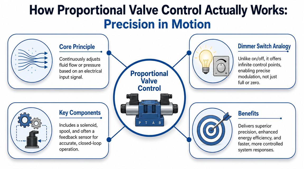
Think of the difference between a room light switch and a dimmer. A standard solenoid valve is the switch. A proportional valve is the dimmer. Instead of fully open or fully closed, the valve can sit somewhere in between and hold that position.
That's the basic principle, but on a hydraulic machine the consequences are much more useful. The spool position changes the metering area. The metering area changes the flow or pressure. That changes actuator speed, force, and acceleration.
A simple visual helps before getting into the details.
The signal path from controller to spool
At the electrical end, the controller sends a reference signal. In proportional systems, the valve driver converts that reference, typically ±10 VDC or 4–20 mA, into a regulated coil current, as described in Atos electrohydraulic proportional control guidance.
The key point is simple. The controller isn't really commanding voltage to the spool. It's commanding a coil current that produces force, and that force moves the spool proportionally.
In a straightforward directional application, the sequence looks like this:
- The controller sends a demand signal. That might come from a joystick, PLC, machine controller, or dedicated amplifier.
- The driver regulates current to the solenoid coil; stable current ensures stable force.
- The solenoid creates magnetic force. More current means more force.
- The spool shifts by a proportional amount. That opens the metering edges by a controlled amount.
- Oil flow changes accordingly. The actuator then moves at a controlled speed or develops controlled pressure.
What the hardware is actually doing
Three parts matter most in day-to-day work:
- The coil or solenoid controls magnetic force.
- The driver or amplifier conditions the command signal and regulates current.
- The spool and body meter the hydraulic oil.
Some valves are open loop. Others use spool feedback for tighter control. In both cases, the practical objective is the same. You want the spool to move predictably and repeatably, without sticking, overshooting, or wandering with temperature.
This video gives a useful view of proportional operation in practice.
Why engineers get caught out
The most common misunderstanding is assuming the electrical command directly equals hydraulic performance. It doesn't. The valve still sits inside a real circuit with pump variation, load changes, oil temperature changes, and pressure drops across metering edges.
That's why two identical valves can behave differently on two machines. The valve may be correct in both cases, but the circuit architecture, actuator sizing, and amplifier setup decide whether the control feels smooth or awkward.
Proportional vs On-Off vs Servo Valves
Choosing the wrong valve type creates problems that no amount of tuning will fully solve. Sometimes proportional control is the right answer. Sometimes it isn't. If the duty is simple, an on/off valve is easier to justify. If the machine demands very high dynamic accuracy, a servo valve may be the proper route.
Hydraulic Valve Control Technology Comparison
| Attribute | On/Off (Solenoid) Valve | Proportional Valve | Servo Valve |
|---|---|---|---|
| Control behaviour | Discrete states | Continuous adjustment | Very fine continuous adjustment |
| Precision | Low for variable motion tasks | Good for most mobile and industrial duties | Highest |
| Response | Abrupt | Controlled and progressive | Very fast and highly responsive |
| Contamination tolerance | Generally more tolerant | Moderate, depends on valve and circuit condition | Usually least tolerant |
| System complexity | Low | Moderate | High |
| Typical use | Simple directional functions | Speed, pressure, ramping, smoother motion | High-performance closed-loop control |
| Commissioning effort | Low | Moderate | High |
| When it’s the wrong choice | Any application needing smooth variable control | Extremely simple functions or ultra-high precision work | Dirty oil, basic machinery, cost-sensitive retrofits |
A broader overview of valve categories is useful if you're comparing circuits side by side. MA Hydraulics has a concise guide to types of hydraulic valves that's worth keeping handy during early selection.
What works in the field
For a tipper body, lock, or simple diverter, an on/off valve is often all you need. Adding proportional control there can complicate the system without delivering much return.
For a loader arm, baler function, saw feed, clamp, or press approach speed, proportional control usually makes much more sense. It allows you to ramp motion, trim speed, and reduce shock without having to build an elaborate servo architecture.
Practical rule: Use the simplest valve that genuinely meets the control task. Anything more creates cost, setup time, and extra failure points.
Where servo still earns its keep
Servo valves belong where the machine really does need top-end dynamic response and tighter control than a proportional valve can realistically provide. That's not most agricultural or site equipment. It's more often specialist industrial motion control, test rigs, or tightly controlled production machinery.
The mistake is assuming servo is automatically better. It's only better when the application can justify the cleanliness, integration effort, and control sensitivity that come with it. On many retrofits, proportional hardware gives the better engineering result because the rest of the machine isn't built to support servo-level performance anyway.
Selecting the Right Proportional Valve for Your Application
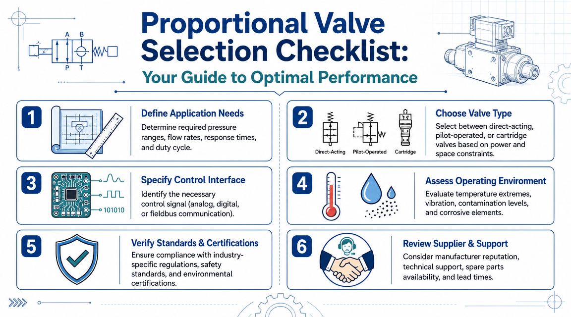
A proportional valve shouldn't be selected from the catalogue backwards. Start with the job the machine has to do, then choose the valve that supports it. Too many poor installations come from selecting by port size or mounting pattern first and asking performance questions later.
In the UK, this matters across a wide installed base. Agriculture alone covered about 17.4 million hectares in 2024, and UK construction produced about £151.5 billion in output in 2023, both of which reinforce how much machinery depends on controlled hydraulic motion in day-to-day service, as noted by Fluid Power Journal's discussion of proportional valve use in mobile equipment.
Start with the hydraulic duty
Before looking at brands or electronics, pin down the machine requirement:
- Flow demand: What actuator speed do you need through the duty cycle?
- Pressure condition: Is the valve controlling motion under light load, full load, or both?
- Control objective: Are you trying to control speed, force, pressure, or just soften starts and stops?
- Duty profile: Is this intermittent machine movement or a function that runs for long periods?
If the flow estimate is uncertain, use a proper sizing method rather than guessing. A simple reference such as these hydraulic flow rate calculations helps prevent a very common mistake, which is choosing a valve that is physically convenient but poorly matched to the actuator.
Open loop or closed loop
This choice affects both cost and behaviour.
Open-loop proportional control is often enough where the machine needs adjustable speed and manageable ramping, but doesn't need exact repeatability under changing load. Many mobile and general industrial functions fall into this group.
Closed-loop proportional control becomes the better choice when the machine has to maintain a tighter result despite load variation, oil temperature shift, or external disturbance. That may involve spool feedback, pressure feedback, position sensing, or a higher-level controller managing the loop.
A practical way to decide is to ask one question. If the load changes, can the machine tolerate some change in speed or position? If yes, open loop may be fine. If no, you need feedback somewhere.
The valve is not always the limiting factor
On retrofits, engineers often expect the new proportional valve to transform machine behaviour on its own. Sometimes it does. Often it doesn't.
What usually limits the result is one of these:
- Contaminated oil
- Poor actuator sealing or internal leakage
- Inadequate wiring and signal quality
- A circuit with too much uncontrolled pressure drop
- An oversized valve on a very small flow task
One option for component selection and application support in this area is MA Hydraulics Ltd, which supplies proportional, CETOP, modular, and inline valve options for mobile and industrial systems. The important point is the process, not the badge on the box. Match the valve, driver, and circuit to the actual duty.
When a proportional valve is the wrong answer
If the machine only needs a simple switched function, don't add proportional control because it sounds more advanced. Mechanical flow control with a standard directional valve can still be the right answer for steady and uncomplicated tasks.
The opposite mistake also happens. Engineers choose a proportional valve where the application really demands a servo-grade response or much tighter closed-loop behaviour than a standard proportional setup can offer. In both cases, the problem isn't the valve. It's the mismatch between expectation and system design.
Practical Tuning and Integration Guidance
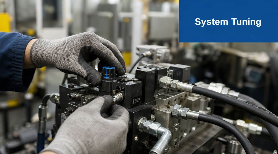
Many installations encounter difficulties. The valve is correctly sized, the wiring is complete, the machine starts, but the motion still isn't right. It jerks off neutral, hunts at low speed, or gets inconsistent as oil temperature rises. That's usually a tuning problem, not a valve problem.
Current control comes first
For proportional coils, the key control variable is current, not voltage. Coils are commonly operated at 12 VDC or 24 VDC, many manufacturers specify coil currents around 1.0 to 2.0 A, and PWM control is commonly recommended to reduce heating and maintain resolution, as explained in this proportional valve current control guidance.
That matters on site because coil resistance changes with temperature. If you try to tune by fixed voltage alone, the spool position won't remain as stable as you think once the machine warms up.
Tune the amplifier around the current the valve needs at real operating temperature, not around what the coil happened to do during a cold bench check.
The settings that matter most
Most practical setups come down to a handful of amplifier parameters:
-
Minimum current
This gets the spool moving cleanly off neutral and helps overcome stiction. Too little and the function feels dead around zero. Too much and the actuator jumps. -
Maximum current
This limits top spool travel. Set it too low and the machine never reaches required speed. Set it too high and the operator gets an over-sensitive top end with wasted heat across the valve. -
Ramp up and ramp down
These settings shape acceleration and deceleration. They are usually the quickest way to remove shock loads and harsh stopping. -
Dither or PWM behaviour
Small oscillation at the coil helps reduce sticking and improve low-speed response. Too much can make the function noisy or unstable.
A commissioning sequence that works
When I'm looking at a machine with a new proportional function, the most reliable sequence is straightforward:
- Verify the hydraulics first: Check pressure supply, return path, actuator condition, and whether the valve is installed in the correct orientation.
- Confirm signal scaling: Make sure the controller output and amplifier input match. A mismatch here creates false faults that look mechanical.
- Set a safe maximum current: Start conservatively so the machine can't run away during first movement.
- Bring in minimum current carefully: Increase only until the spool responds consistently without a jump.
- Tune ramps under load: Don't finalise ramp values with an unloaded actuator if the machine normally works loaded.
- Recheck when warm: Many systems feel acceptable cold and poor once oil and coils reach working temperature.
What usually doesn't work
Two habits cause most headaches. The first is trying to fix a hydraulic sizing problem with electronic tuning. The second is tuning for the empty machine and handing over a loaded one.
If the valve is oversized, the actuator can become difficult to control at small commands. If the pressure drop is badly chosen, the machine may feel lazy at one part of stroke and aggressive at another. No amplifier setting can fully correct a poor hydraulic layout.
Troubleshooting Common Control Problems
When a proportional system misbehaves, random part-swapping wastes time. A better approach is to separate the issue into command, valve movement, and hydraulic response. Check each stage in order and most faults become much easier to pin down.
For a broader fault-finding reference, MA Hydraulics also has a useful page on hydraulic valve problems that lines up well with site-level diagnostics.
Oscillation or hunting
Problem: The actuator keeps correcting itself, surges, or won't settle smoothly.
Likely causes:
- Gain or sensitivity set too aggressively
- Air in the hydraulic line
- Mechanical looseness or load instability
- Excessive dither or poor ramp settings
What to do:
Back the tuning off before replacing hardware. Bleed the circuit if air is suspected. Check whether the instability only appears under a certain load condition. If it does, the issue may be in the machine mechanics rather than the valve itself.
Slow or non-linear response
Problem: Nothing seems to happen for part of the command range, then movement arrives suddenly.
Likely causes:
- Minimum current set too low or too high
- Spool sticking from contamination
- Wrong command scaling
- Valve too large for the required flow
What to do:
Check the electrical input and actual driver output first. Then inspect oil condition and filtration history. A dirty proportional valve often shows up first as poor low-end control rather than complete failure.
If the first few per cent of command does nothing and the next bit gives a lurch, look at null adjustment, minimum current, and contamination before blaming the controller.
Drift when the valve should be closed
Problem: The actuator creeps even when neutral is commanded.
Likely causes:
- Internal leakage in the valve
- Cylinder leakage
- Incorrect spool condition at neutral
- Load-induced movement elsewhere in the circuit
What to do:
Isolate the valve from the actuator if possible. That tells you whether the drift is across the valve or inside the actuator. Don't assume all drift is electrical. It often isn't.
No movement at all
Problem: The function is dead.
Likely causes:
- No power to the driver
- Wrong polarity or broken wiring
- Failed coil
- No pilot or supply pressure
- Command signal absent
What to do:
Start with the basics. Power, enable signal, command signal, and coil continuity. Then confirm pressure is available at the valve. A surprising number of “valve faults” turn out to be upstream supply problems.
Partner with MA Hydraulics for Expert Control
Proportional valve control is often the most sensible answer when a machine needs more than switched movement but doesn't justify full servo complexity. Used properly, it gives smoother motion, better control of speed and force, and less mechanical shock across a wide range of mobile and industrial duties.
The important part is using it where it belongs. A proportional valve won't rescue poor oil cleanliness, bad wiring, or a weak circuit design. It also won't always be the right upgrade. Sometimes a basic directional valve is enough. Sometimes the job needs a higher-performance closed-loop solution. Good results come from matching the valve, electronics, and hydraulic layout to the specific duty.
If you're specifying a new system, retrofitting older equipment, or trying to make an existing machine behave properly, technical judgement matters as much as the valve itself. That's where practical application support saves time.
If you need help selecting, integrating, or troubleshooting proportional valve control, contact MA Hydraulics Ltd. Call 01724 279508 today, or send us a message.