
A machine that should be brisk on the ram feels lazy. A conveyor drive hunts instead of running steadily. A fresh power pack build looks right on paper, then comes up short once the oil warms and the job starts cycling. Most of the time, the root cause isn't mysterious. The flow rate calculations were off, or they were oversimplified for the actual duty.
That matters more than ever in drainage, transport and fluid handling work where assumptions can't stay academic. One frequently underserved angle is how to calculate flow rate when the fluid is not water-like, because standard examples usually assume constant density and easy conversions, while real systems in hydraulics, slurry handling and process lines need viscosity- and temperature-aware thinking. In the UK, practical conveyance design stays highly relevant because the Environment Agency's National Flood Risk Assessment 2 shows about 6.3 million properties in England at risk from flooding, which keeps demand high for drainage and conveyance calculations that go beyond textbook examples, with wider context noted in FHWA hydraulic guidance.
Why Accurate Flow Rate is the Heart of Your Hydraulic System
When a hydraulic cylinder moves too slowly, checking pressure is often the first step. Pressure matters, but flow decides speed. If the ram has force but not pace, the system usually has enough pressure potential and not enough oil volume arriving where it needs to go.
That shows up constantly on mobile and industrial kit. A tipper body lifts, but too slowly for a sensible cycle. A clamp closes eventually, but the operator waits. A saw feed works when cold, then drifts once the oil thins. In each case, poor flow rate calculations push the problem downstream into heat, wasted energy and awkward troubleshooting.
What flow errors look like in practice
On real equipment, the symptoms are often indirect:
- Slow actuator travel: The cylinder or motor works, but the machine misses its intended cycle behaviour.
- Hot running oil: Excessive restriction or recirculation turns power into heat instead of motion.
- Noisy suction side: A pump starved by poor line sizing often complains long before it fails.
- Component mismatch: The pump, valve bank and hoses may all be individually serviceable, yet wrong together.
A lot of avoidable confusion comes from treating flow as a catalogue number rather than a system value. A pump may have a theoretical displacement, but the circuit still has to pass that oil through valves, fittings, manifolds, filters and hose runs without choking it. If you're checking a live machine, a hydraulic flow gauge helps separate theory from what the circuit is delivering.
Practical rule: If a machine is slow everywhere, start at the pump. If it's slow only on one function, start at the restriction.
Why the calculation has to fit the application
A clean bench calculation can still fail in service. Oil temperature changes viscosity. Wear reduces actual output. Pipework routes around the machine rather than through an ideal straight line. A compact power pack that fits the available footprint may need tighter attention to reservoir, cooling and return flow than a larger installation.
Good flow rate calculations aren't about showing the maths. They're about making sure the actuator speed, pump displacement, motor speed, valve capacity and line sizing all agree with each other before metal gets cut and hoses get crimped.
The Core Formulas for Calculating Hydraulic Flow
Hydraulic flow rate calculations start with two formulas. One describes flow through a passage. The other describes the output of a positive displacement pump. If you keep these two straight, most sizing work becomes much easier.
Flow through a pipe or hose
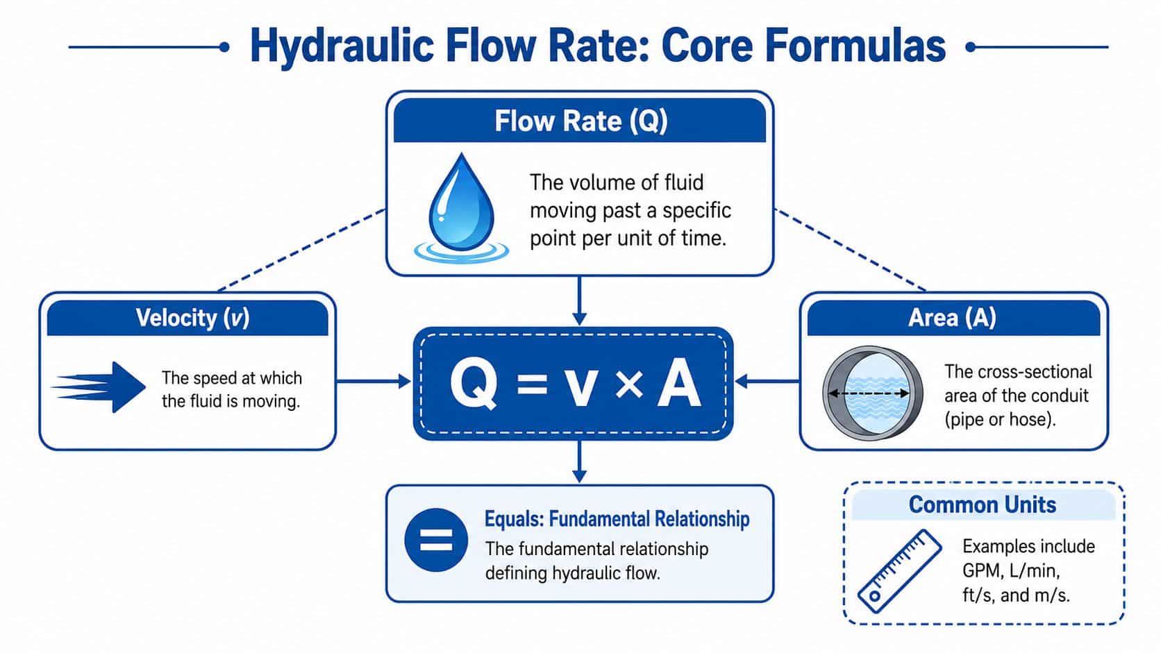
For any fluid moving through a cross-section, the basic relationship is:
Q = v × A
Where:
- Q is the volumetric flow rate
- v is fluid velocity
- A is cross-sectional area
In hydraulic work, it's common to calculate using metric dimensions and then express the final answer in L/min. The important detail is consistency. If the area is in square metres and velocity is in metres per second, the result comes out as cubic metres per second before conversion.
A common mistake is using outside diameter instead of internal diameter when finding area. Flow doesn't care about the hose wall. It only cares about the open passage available to the oil.
Pump output from displacement and speed
For gear pumps and many common hydraulic pump selections, the most useful formula is:
Flow rate (L/min) = (Pump displacement in cc/rev × Speed in RPM) / 1000
That works because pump displacement is the volume moved in one revolution. Multiply by rotational speed and you have a theoretical volume per minute.
Rearrange it when needed:
Pump displacement (cc/rev) = (1000 × Required flow in L/min) / Speed in RPM
This is usually the fastest route from machine requirement to component choice. If a cylinder speed target translates into a certain oil demand, and the prime mover speed is known, you can estimate the pump displacement very quickly.
What these formulas tell you and what they don't
These are theoretical formulas. They are essential, but they don't tell the whole story. In service, actual flow can differ because of internal leakage, pressure losses and operating temperature.
That doesn't make the formulas less useful. It means they should be used as a starting point for component selection, not as a guarantee of field performance.
A practical way to think about the two formulas is this:
| Formula | Best used for | Typical decision |
|---|---|---|
| Q = v × A | Hose, pipe and port sizing | Is the line too small for the oil velocity? |
| Displacement × RPM | Pump and motor selection | What pump size or motor speed should I expect? |
Keep the units tidy from the start
Most workshop errors happen before the calculator is wrong. They happen because one figure is in millimetres, another is in metres, and the final answer gets written down in the wrong unit. Standardise early:
- Use litres per minute for hydraulic flow
- Use millimetres for diameters when measuring components
- Use metres per second for line velocity
- Use bar for pressure in general hydraulic discussions
If you keep one consistent unit system all the way through, the maths stops being the difficult part. The harder part becomes judgement, such as whether a hose velocity is sensible for suction duty or whether a chosen gear pump still suits the machine once the duty cycle gets harsher.
Essential Units and Practical Conversion Tables
Bad conversions waste more time than difficult calculations. A technician may diagnose a “weak pump” when the underlying issue is that someone mixed litres per minute, litres per second and cubic metres per second in the same worksheet.
In UK hydraulic practice, it's usually simplest to run calculations in metric units throughout. Keep flow in litres per minute, pressure in bar, dimensions in millimetres or metres, and only convert at the edges when reading older specifications.
Common metric hydraulic unit conversions
The table below is a quick reference. Use it to move figures into one consistent format before doing the primary calculation.
| From | To | Multiply By |
|---|---|---|
| L/min | L/s | 1/60 |
| L/s | L/min | 60 |
| L/min | m³/s | 0.001/60 |
| m³/s | L/min | 60,000 |
| mm | m | 0.001 |
| m | mm | 1000 |
| bar | Pa | 100,000 |
| Pa | bar | 0.00001 |
| cm³ | L | 0.001 |
| L | cm³ | 1000 |
Where conversions go wrong
The usual traps are predictable:
- Diameter and area confusion: Diameter might be measured in millimetres, but area must be calculated in square units.
- Per second and per minute mixed together: Velocity often uses metres per second, while pump flow is commonly discussed in litres per minute.
- Pressure units copied without checking: Imported data sheets may list pressure differently from the rest of the circuit notes.
If you're pairing pressure and flow calculations, it helps to keep the pressure side in the same metric framework as well. This short guide on how pressure is calculated is useful when you need to connect actuator force, pressure requirement and flow demand without switching mental gears.
A practical shop-floor habit
Write the unit beside every number as you enter it. Not at the end. Not from memory. At the start.
That sounds basic, but it prevents the common situation where one person assumes a pump is listed in displacement per revolution and another reads the same figure as a flow rating. It also makes older imperial documents easier to interpret. You may still see GPM or PSI on legacy equipment or US-origin parts. Read them if you must, but do the actual hydraulic sizing in metric so the rest of the system stays consistent.
Small conversion errors don't stay small in hydraulics. They turn into the wrong pump, the wrong hose and a machine that never behaves as intended.
Worked Example Calculating Pump and Motor Flow
A calculation becomes useful when it points to a real component choice. For most mobile and industrial systems, that means linking the oil demand to a pump displacement, then checking what the same flow would do on the motor side.
Example one sizing a gear pump
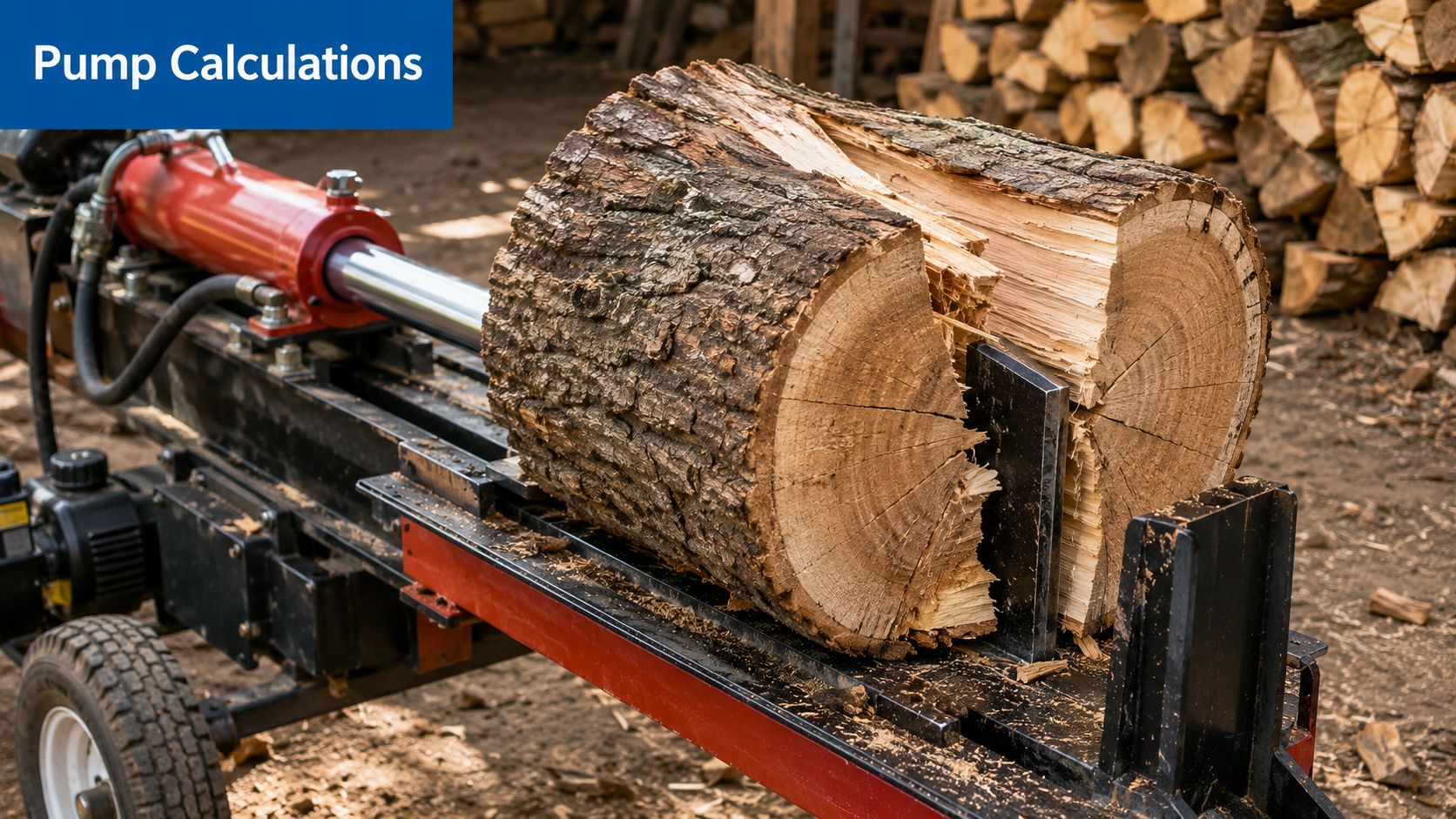
Take a straightforward machine case. A log splitter needs 45 L/min to achieve the required cylinder speed. The petrol engine runs at a steady 3000 RPM. The question is simple. What pump displacement is needed?
Use the rearranged pump formula:
Pump displacement (cc/rev) = (1000 × Required flow in L/min) / Speed in RPM
Substitute the values:
- Required flow = 45 L/min
- Speed = 3000 RPM
So:
Displacement = (1000 × 45) / 3000 = 15 cc/rev
That gives a theoretical requirement of 15 cc/rev.
Turning the answer into a selection decision
This is the point where engineers sometimes stop too early. Getting 15 cc/rev is not the end. It's the start of the selection process.
You would then check:
- Pump group and mounting: The displacement needs to exist in a suitable frame size, such as a Group 2 gear pump if that fits the drive arrangement.
- Rotation direction: Clockwise, anti-clockwise or reversible as the application demands.
- Pressure duty: The pump must suit the actual working pressure and the relief setting.
- Shaft and flange details: A mathematically correct pump is still wrong if it won't couple to the engine or PTO.
- Oil type and operating temperature: These affect real-world behaviour, especially during cold starts.
For compact assemblies or integrated systems, a hydraulic power unit may be specified instead of selecting loose components one by one. In that case, the same flow calculation still drives the build, but reservoir, motor, valve block and return arrangement need to be matched around it.
Example two checking motor speed from available flow
Now reverse the thinking. Suppose you have a 22 cc/rev gear motor on a conveyor, fan drive or small winch circuit. The supply available to that motor is 40 L/min. What theoretical speed should you expect?
Rearrange the same relationship:
Motor speed (RPM) = (Flow in L/min × 1000) / Displacement in cc/rev
Substitute the values:
- Flow = 40 L/min
- Displacement = 22 cc/rev
So:
Motor speed = (40 × 1000) / 22 = 1818.18 RPM
The theoretical speed is therefore about 1818 RPM.
That figure is useful, but treat it as an ideal starting point. Real speed can differ depending on leakage, pressure load and the way the circuit controls return flow.
A visual walkthrough can help if you're checking your own method against a live job:
What these examples teach in practice
The pump example answers, “What size do I need to make the machine move at the required speed?” The motor example answers, “Given this flow and this displacement, what rotational speed am I likely to get?”
Those are different questions, and mixing them up causes frequent design errors. A few practical reminders help:
- Cylinder speed drives pump flow demand. Start with actuator speed, then calculate backwards.
- Motor displacement trades speed for torque behaviour. A larger displacement motor turns slower for the same flow.
- Theoretical figures are selection figures. They must then be checked against the pressure side of the application.
- Prime mover speed matters. An engine-driven system at one speed and an electric motor-driven system at another may need completely different pump displacements for the same target flow.
If the machine requirement is stated as speed, convert it into flow first. Selecting the component before doing that usually leads to compromise later.
Worked Example Pipe and Hose Diameter Calculations
Once the pump produces the oil flow, the circuit still has to carry it properly. During this phase, many otherwise decent hydraulic systems lose efficiency. Hose and pipe sizing looks secondary until the machine runs hot, chatters on the suction side or drops speed under load.
The key relationship is still the same one used earlier:
Q = v × A
Here, you already know the flow rate. The job is to choose an area large enough to keep the velocity sensible for that part of the circuit.
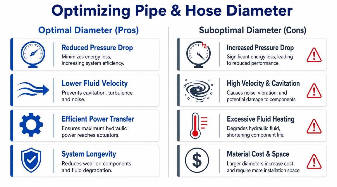
Why diameter choice affects more than packaging
A hose that's too small raises fluid velocity. Higher velocity usually means more friction, more pressure drop and more heat. It also makes the circuit less forgiving of fittings, adaptors and bends.
A hose that's too large isn't automatically ideal either. It costs more, takes up more room and can make a compact machine awkward to route and support. On mobile machinery especially, oversized hose can become a practical installation problem rather than a hydraulic benefit.
Common target velocities
As a rule of thumb, designers often aim for different velocity ranges depending on line function:
| Line type | Typical target velocity |
|---|---|
| Suction lines | 0.5 to 1.2 m/s |
| Pressure lines | 3 to 5 m/s |
| Return lines | 1.5 to 2.5 m/s |
These aren't magic numbers. They're practical targets that help avoid obvious problems. The correct choice within the range depends on duty, oil condition, line length and how compact the system needs to be.
Worked example for a pressure hose
Use the earlier pump example flow of 45 L/min. The task is to find the minimum internal diameter for a pressure hose if you want to keep fluid velocity at or below 5 m/s.
Step one convert flow into cubic metres per second
Start by converting 45 L/min into m³/s.
- 45 L/min = 0.045 m³/min
- Divide by 60 to convert minutes to seconds
So:
Q = 0.00075 m³/s
Step two calculate required area
Using Q = v × A, rearrange for area:
A = Q / v
Substitute:
- Q = 0.00075 m³/s
- v = 5 m/s
So:
A = 0.00075 / 5 = 0.00015 m²
Step three convert area into diameter
For a round hose:
A = πd² / 4
Rearrange for diameter:
d = √(4A / π)
Substitute the area:
d = √(4 × 0.00015 / π)
This gives an internal diameter of about 0.0138 m, which is 13.8 mm.
So the minimum internal diameter to keep velocity at or below 5 m/s is roughly 14 mm. In practice, you would then select the nearest suitable hose bore and check the actual internal diameter from the hose specification, not just the nominal size.
What the result means on the machine
If you chose a smaller pressure hose than that calculation supports, the oil would move faster than intended. That can show up as:
- Higher pressure loss across the line
- More heat generated in continuous duty
- Sharper sensitivity to elbows, tees and adaptors
- Reduced response quality at the actuator
If you go larger, velocity drops, which often helps pressure loss. But there's a trade-off in cost, weight and routing. On a stationary industrial power pack, that may be acceptable. On compact mobile equipment, it may not be.
A good habit is to calculate the line based on target velocity, then sense-check the physical routing. If the line is long, heavily bent or packed with fittings, treat the simple result as the floor, not the final answer.
The hose doesn't just carry flow. It shapes how much of that pump output arrives at the actuator in useful form.
Common Mistakes Application Tips and Next Steps
Most costly hydraulic errors don't come from difficult maths. They come from skipping one practical check after another until the system is assembled around a bad assumption.
Mistakes that keep turning up
Some problems appear repeatedly across mobile plant, agriculture and industrial equipment:
- Using theoretical pump output as delivered flow: Real systems rarely behave exactly like a clean formula.
- Ignoring valve capacity: A pump may be sized correctly while a valve bank becomes the actual choke point.
- Forgetting fittings and bends: Pressure drop isn't only in the hose length. It also builds through adaptors, elbows and restrictive ports.
- Treating all fluids as water-like: In process lines, slurries and temperature-sensitive fluids, viscosity and density assumptions can change what “acceptable” flow really means.
- Selecting by catalogue habit: Repeating the same hose size or pump group from the last job can be convenient and wrong.
Application tips that improve system behaviour
Flow rate calculations sit at the centre of wider power pack design. Once the expected flow is known, several other decisions become clearer.
A compact reservoir may still work, but the thermal margin gets tighter. A return line that looks acceptable on paper may create avoidable backpressure in service. A cooler that seemed optional can become necessary once the duty cycle moves from intermittent to repeated operation.
For agricultural and mobile equipment, instrumentation and monitoring also matter because operators often judge performance by cycle consistency rather than by reading gauges. If you're working around tanks, liquid handling or field systems where measurement affects output, this guide to boosting farm productivity gives useful context on how monitoring supports day-to-day operational decisions.
What tends to work best
The best results usually come from a simple sequence:
- Start with actuator speed or motor speed requirement
- Convert that into flow
- Choose pump or motor displacement to suit the available drive speed
- Check hose and port velocities
- Review the whole circuit for restrictions, heat and serviceability
That sequence prevents the common mistake of selecting hardware first and trying to force the maths to justify it afterwards.
If you've got a live project, a repeated overheating issue, or a new machine build that needs the pump, motor and plumbing matched properly, speak to MA Hydraulics Ltd. Call 01724 279508 today, or send us a message.
