
A hydraulic arm stops just short of its target. The operator nudges the control again, the load overshoots, and the cycle starts over. On paper, the cylinder, valve and controller all appear correctly specified, yet the machine still wastes time correcting position.
That problem rarely comes from one faulty component. Precision positioning in hydraulic systems depends on the complete chain, including the actuator, oil, valve, pump, structure, feedback sensor, controller and load. A high-resolution sensor can't compensate for excessive leakage, and a fast valve can't deliver stable motion if the mechanical arrangement is flexible.
For OEMs, maintenance teams and system integrators, the practical question isn't just how accurately a controller can calculate a position. It's whether the machine can reach and hold that position repeatedly, under the pressure, temperature, friction and load conditions found in service.
What Precision Positioning Means in Hydraulic Systems
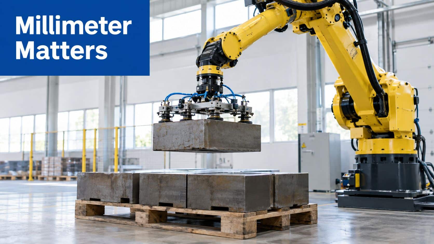
Consider a materials-handling manipulator placing a steel component into a fixture. The arm may reach the target during the first cycle, but the result changes when the oil warms, the load varies or the cylinder changes direction. A small amount of drift can force an operator to intervene, slow the line and increase the risk of placing the component against the fixture rather than into it.
A similar issue appears on agricultural machinery. An implement might need to maintain a consistent working depth across uneven ground. If the cylinder creeps or responds unevenly, the implement follows the hydraulic error rather than the intended control signal. The machine may still function, but it won't produce repeatable work.
Precision positioning means controlling an actuator so that it reaches a commanded location and remains there within the tolerance required by the application. That tolerance could be relatively broad for a simple lift, or very tight for automated assembly, test equipment and machine tooling. The right target depends on the process, not on a marketing label attached to a valve or sensor.
Hydraulics create a particular challenge because oil, seals, pipework and metal structures all influence movement. Fluid behaves as a spring under pressure, seals generate friction, valves can pass a small amount of flow at neutral, and the load itself may store or release energy. The controller sees the resulting position error, but the root cause may sit several components away.
Practical rule: Specify positioning accuracy as a complete system requirement. Don't specify the sensor first and assume the rest of the circuit will automatically support it.
The most reliable designs connect mechanical stiffness and hydraulic power to suitable feedback and control. That means selecting components for the load and duty cycle, commissioning them methodically, then checking performance while the machine performs its real work.
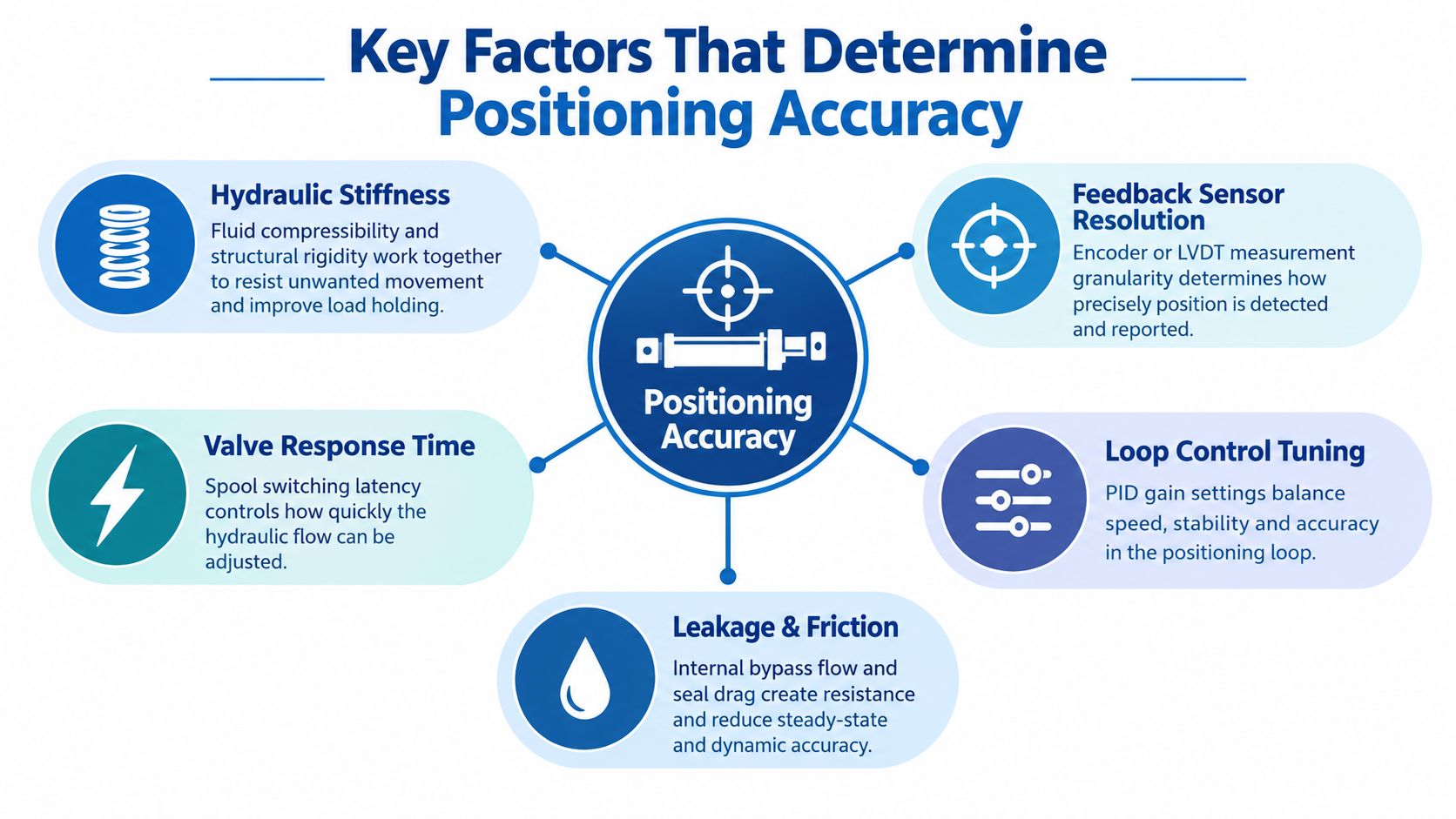
Key Factors That Determine Positioning Accuracy
A hydraulic positioning system can miss its target for several different reasons. The five factors below interact, so replacing one component without checking the rest often produces only a temporary improvement.
Hydraulic stiffness
Stiffness describes how little the actuator and supporting structure move when the load changes. A long hose, flexible bracket or cylinder with an unfavourable mounting arrangement can allow the load to deflect even when the controller reports the correct command.
Pressure also affects the result. As the load changes, the pressure required to hold the actuator changes. A system with more compliance allows greater movement before the pressure and position settle. Use compact pipework where practical, sturdy mounting plates and an actuator suited to the load path.
Leakage
Internal leakage across a valve or past a cylinder seal allows movement without a corresponding command. External leakage is easier to spot, but internal bypass can remain hidden until the load is held for a period or the oil reaches operating temperature.
A drifting axis should therefore be tested under a defined load, with pressure and position recorded over time. Replacing a controller won't cure a worn seal or a valve whose neutral condition no longer isolates the actuator.
Fluid compressibility
Pressurised oil stores energy. Air entrainment makes the effect more pronounced, producing a soft or spring-like response. The actuator may continue moving after the valve has reduced flow, then rebound as stored energy is released.
Bleeding the system, preventing air ingress and keeping the reservoir correctly configured are basic but important measures. The hydraulic circuit also needs enough flow capacity to fill and control the actuator without creating unstable pressure changes.
Friction
Seal drag, guide friction and spool friction can prevent an actuator from moving at very low command levels. The controller increases the signal until the static friction breaks free, then the actuator moves too far. This stick-slip behaviour is especially troublesome during slow approach movements.
Cylinder alignment, seal selection, contamination control and valve quality all matter. A position sensor can identify the error, but it can't remove mechanical friction from the system.
Load dynamics
Inertia, changing centre of gravity and external forces alter the response throughout the movement. A gripper carrying a heavy component behaves differently from the same gripper moving empty. An agricultural implement also experiences changing soil resistance, which can push the actuator away from its commanded position.
Pressure monitoring gives the maintenance team useful evidence when position alone doesn't explain the failure. A hydraulic pressure monitoring system can help correlate load changes with actuator behaviour and distinguish a control problem from a mechanical or hydraulic one.
The accuracy target should be considered in context. Ordnance Survey states that typical field GNSS surveys achieve accuracies of a few centimetres relative to a global datum, while the highest precision GNSS positions reach the 2 mm level horizontally in its guide to coordinate systems in Great Britain. Hydraulic systems don't automatically need that level of performance, but the comparison illustrates why every source of compliance and error must be understood when an industrial process has a demanding tolerance.
Control Approaches for Precise Hydraulic Motion
The control architecture determines whether the system can detect and correct an error. An open-loop circuit sends a command without measuring the resulting position. It can work for straightforward extend-and-retract duties where end-of-stroke switches are sufficient, but it can't compensate continuously for load changes, leakage or thermal effects.
A closed-loop system compares the commanded position with feedback from an encoder, LVDT or another suitable transducer. The controller uses the difference, or error, to adjust the valve command. This doesn't remove the physical causes of error, but it gives the system a way to respond to them.
Proportional and servo control
A proportional valve varies flow in response to an electrical command. It offers a practical route to controlled speed and position for many industrial and mobile applications, particularly where the machine needs smoother control than a basic directional valve can provide. Performance still depends on spool characteristics, deadband, hysteresis, contamination and the quality of the feedback loop.
Servo valves are intended for more demanding dynamic control. They can respond rapidly to small command changes, but they also require cleaner oil, careful filtration, suitable electronics and disciplined commissioning. A servo valve won't rescue an incorrectly sized pump or a flexible cylinder mounting.
Electrohydraulic actuation combines hydraulic force density with electronic feedback. It suits applications where the power available from hydraulics is valuable but the machine must also follow a controlled position profile. Engineers planning broader machine automation solutions should treat the hydraulic axis as part of the automation system, rather than as an isolated power circuit.
| Control Type | Accuracy | Cost Level | Typical Applications |
|---|---|---|---|
| Open-loop directional control | Limited, dependent on stops and operator or timing | Lower | Basic lifting, clamping and end-position movement |
| Closed-loop proportional control | Good where load variation and response demands are moderate | Moderate | Agricultural implements, handling equipment and general industrial axes |
| Closed-loop servo control | High, with fast correction when the mechanics and feedback support it | Higher | Test rigs, machine tooling, forming and demanding automation |
| Electrohydraulic position control | Selected to match the actuator, sensor and control architecture | Application-dependent | High-force automated machinery and controlled motion systems |
The choice should follow the duty, not the valve catalogue. A proportional valve may be the sensible option when the axis moves at moderate speed and the tolerance allows a controlled approach. Servo control becomes more appropriate when the process needs rapid correction, fine motion or repeatable dynamic profiles.
For practical guidance on circuit selection, proportional valve control should be considered alongside sensor resolution, pump response, valve neutral behaviour and the controller’s tuning capability. The valve, feedback device and software must be treated as one control loop.
Choosing the Right Components for Precision Positioning
Component selection is where positioning theory becomes a machine that either performs reliably or creates recurring service calls. Start with the load path and required movement, then work backwards through the actuator, valve, pump and feedback rather than choosing each item independently.
Select the valve for controllability
Check the valve’s flow rating, pressure capability, command signal, spool overlap and response characteristics. Excess capacity can make low-speed control difficult, while insufficient capacity creates lag and heat. A valve should provide controllable flow across the working range, not merely enough maximum flow to move the actuator quickly.
Proportional valves suit many applications that need variable movement without the complexity of a high-performance servo circuit. Where the process demands rapid, fine correction, a servo valve may be justified, provided the oil cleanliness and electronics support it.
Match the pump to the motion
The pump must supply the required flow without making the control loop fight unnecessary pressure variation. Gear pumps are often suitable for dependable, straightforward power units, while a more responsive pump arrangement may be needed where the axis demand changes sharply.
The important point is consistency. A pump that produces unstable delivery, excessive ripple or insufficient reserve can appear to be a controller fault. Check the pump, relief circuit and accumulator arrangement as part of the response assessment.
Choose the actuator and sensor together
Cylinder bore, rod diameter, mounting, seal package and guidance affect force, deflection and friction. A well-chosen cylinder with poor alignment can perform worse than a simpler actuator installed on a sound load path.
The feedback device must measure the movement that matters. An LVDT or linear transducer mounted close to the actuator can provide direct position information, while an encoder may suit a rotary axis or mechanically linked mechanism. Consider resolution, repeatability, protection, installation space and how sensor failure will be detected.
Keep the manifold compact and serviceable
Every unnecessary hose, cavity and flexible connection can add compliance or delay. A carefully designed manifold reduces plumbing, shortens flow paths and makes testing easier. Review the hydraulic manifold design before finalising the valve and actuator arrangement, because the manifold is part of the dynamic circuit, not just a convenient mounting block.
MA Hydraulics Ltd is one option for sourcing hydraulic components, assembling Hydronit mini power packs to specification and manufacturing bespoke industrial power packs up to 11 kW. The same selection discipline applies whether the final system uses a gear pump, proportional valve, servo valve, linear sensor or a combination of these components.
Commissioning and Tuning Your Hydraulic System
A carefully designed circuit can still behave badly if commissioning begins with aggressive controller settings. Start with the machine safe, unloaded where possible and instrumented so that the team can see pressure, command, feedback and position error rather than relying only on audible noise or operator feel.
-
Complete the initial checks. Confirm plumbing, electrical connections, valve orientation, sensor wiring, oil level, filtration and mechanical fasteners. Verify that the feedback direction agrees with the controller. Reversed feedback can turn a correction into positive feedback.
-
Verify pressure and flow. Check relief settings, counterbalance behaviour and available flow against the design requirement. Look for pressure spikes during acceleration and stopping. A system that reaches the target only because a relief valve is opening isn’t under proper control.
-
Calibrate the sensor. Establish the physical reference position, zero the transducer and confirm the full travel. Move the actuator slowly and compare the measured position with an independent mechanical reference. Check that the signal remains stable when the actuator is stationary.
-
Tune the loop gradually. Begin with proportional gain at a conservative level. Increase it until the actuator responds firmly, then adjust integral action only as needed to remove sustained error. Add derivative action carefully where the signal is clean and the application benefits from damping. Excessive gain can cause oscillation, while insufficient gain can leave drift and sluggish correction.
-
Validate under working conditions. Test approach, stop, reverse and hold behaviour with representative loads. Record repeatability, settling behaviour, pressure and temperature. Repeat the test after the oil reaches normal operating condition, because seal friction and leakage can change as the system warms.
Commissioning advice: Tune for the complete machine, not for a bare cylinder on a test bench. The load, tooling and mounting structure are part of the control response.
A short step-response test can reveal more than a long production run. Command a controlled movement, observe the overshoot and settling, then make one change at a time. Keep a record of the settings so that maintenance staff can identify whether a later fault comes from component wear or an altered controller parameter.
Real-World Case Studies in Precision Positioning
The following examples are practical application scenarios, not claims of measured results from named installations. They show how an engineer can trace a positioning complaint back to component selection rather than treating the controller as the only possible cause.
Materials handling
An OEM building a manipulator finds that a gripper reaches its target inconsistently. The original circuit uses a directional valve and relies on timing to estimate position. A more suitable design would use a proportional valve with a linear position sensor, then tune the approach and deceleration around the actual gripper load.
The improvement comes from measuring the result and controlling flow continuously. The engineer should still check cylinder friction, mounting deflection and valve deadband, because the sensor only reports the error.
Agricultural machinery
An implement operator reports depth drift during a long working cycle. The first inspection finds no obvious external leak, so the team tests the cylinder while holding a representative load and compares pressure decay with position change. Internal seal leakage, air in the circuit or a counterbalance setting can all contribute to the symptom.
The remedy may involve a seal inspection, improved air removal, revised load-holding hardware or a more appropriate feedback arrangement. Changing the gain without finding the source of the drift may mask the problem briefly and make the system less stable.
Manufacturing equipment
A forming or positioning machine oscillates as it approaches the setpoint. The team checks whether the sensor signal is noisy, whether the valve is oversized for the required low-speed flow and whether proportional gain is too high. A controlled reduction in gain, improved signal filtering and a valve with more suitable flow characteristics may produce a calmer approach.
The same problem-solving approach applies beyond hydraulics. Engineers looking for examples of how operational changes can support workshop performance can see how helps shops, but the hydraulic diagnosis still needs to begin with the load, actuator and feedback loop.
In each scenario, the component choice influences the achievable positioning performance. The controller can only work with the hydraulic response it receives.
Common Failure Modes and Troubleshooting Guide
A positioning fault often gives a recognisable symptom. Start with the symptom, then test the likely physical cause before replacing electronic components.
The position drifts while holding
Check for internal valve leakage, cylinder seal bypass, hose movement and changes in load pressure. Isolate the actuator where the circuit allows, then monitor whether the position changes with the command removed. If drift changes with oil temperature, inspect leakage and seal friction rather than assuming the sensor has failed.
Also verify the sensor reference. A loose transducer bracket or damaged linkage can report movement that doesn’t match the actuator, creating a false impression of hydraulic drift.
The axis oscillates around the target
Oscillation usually points to an overly aggressive loop, excessive compliance or a delayed response. Reduce proportional gain cautiously, check integral action and inspect the feedback signal for noise. If the actuator continues to move after the valve command changes, investigate trapped air, hose volume and load-induced energy.
Valve overlap and spool friction can also create a repeating cycle. The controller increases the command to overcome the deadband, the spool then moves too far, and the loop reverses its correction.
The response is slow or lagging
Confirm available pump flow, valve command scaling and actuator sizing. A restricted filter, incorrect orifice, low supply pressure or counterbalance setting can limit movement. Check whether the controller is deliberately ramping the command to protect the load.
A slow response may be acceptable for a lifting function but unacceptable for synchronised automation. Define the required motion profile before increasing gain, because more gain can’t compensate for a restricted hydraulic path.
Repeatability changes between cycles
Look for changing load conditions, temperature, contamination, mechanical friction and sensor mounting. Compare the first movement with later movements and record pressure as well as position. A change that follows temperature may indicate seal behaviour or leakage, while a change linked to load may indicate insufficient stiffness or an unsuitable control strategy.
Use a structured fault sequence:
- Confirm the symptom: Record command, feedback, pressure, temperature and load condition.
- Separate electrical from hydraulic causes: Check sensor supply and signal stability before changing gains.
- Inspect the physical circuit: Look for air, leakage, loose mounts, damaged seals and restricted flow.
- Change one variable: Make one adjustment, repeat the same test and record the outcome.
- Revalidate production duty: A repair is incomplete until the system performs under its normal load and cycle.
Maintenance principle: Don’t tune around a worn component. Restore the mechanical and hydraulic condition first, then tune the control loop.
Getting Started with Precision Positioning Solutions
Reliable hydraulic positioning starts with five questions. Is the structure stiff enough? Is leakage under control? Is the oil circuit free from avoidable compliance and air? Can the valve deliver the required flow smoothly? Does the feedback device measure the movement that the process actually needs?
From there, select the control approach, match the pump and actuator, design the manifold carefully and commission the complete machine under representative load. Ongoing checks should include sensor mounting, seal condition, oil cleanliness, pressure behaviour and controller settings.
Precision positioning isn’t achieved by buying the most advanced valve in isolation. It comes from integrating mechanical design, hydraulic power, feedback and tuning so that every part supports the same positioning target.
MA Hydraulics Ltd supplies hydraulic components and bespoke power solutions for OEM, agricultural, materials-handling and industrial applications, including component selection support and custom power pack assembly. Phone 01724 279508 today to discuss your precision positioning requirements, or contact MA Hydraulics Ltd with details of your actuator, load and control system.
