

You're usually looking at a manifold redesign when something upstream has already gone wrong. The machine is too bulky. Hose runs are vulnerable. Service access is poor. A valve bank works on paper but becomes awkward once it's mounted on a telehandler, press, baler or power pack. That's when hydraulic manifold design stops being a drawing exercise and becomes an engineering decision with real cost behind it.
Good manifold work isn't about packing as many functions as possible into a lump of metal. It's about controlling oil properly, making the block safe to manufacture, and ensuring the finished assembly can survive actual UK working conditions. In mobile plant that means vibration, weather, contamination and tight packaging. In industrial settings it usually means heat, long duty cycles, maintenance access and repeatability.
The expensive mistakes nearly always begin before machining. A gallery is undersized. A cavity family is mixed up. A port is placed where no spanner will reach. Or the design works hydraulically but can't be drilled cleanly without awkward cross-passages and weak wall sections. Those are avoidable problems if the design is approached in the right order.
Defining Your Design Foundation
A manifold usually starts going wrong before anyone opens CAD. The trouble begins with an incomplete brief. Pressures are assumed, flows are rounded, a holding function is treated like a standard service line, and the block is laid out before the duty has been pinned down. In UK mobile and industrial work, that shortcut is expensive because the finished manifold still has to be machinable, serviceable and compliant in the environment it will operate in.
Start by fixing the circuit specification. That means agreeing the hydraulic function, the pressure limits, the flow requirement, and the logic sequence before cavity positions or drillings are discussed. If those points are still changing while the manifold is being arranged, the design ends up carrying compromises that show up later as heat, instability, awkward machining or poor access.
Start with the operating reality
The schematic is only the start. The design basis needs the actual operating envelope behind it.
Record the maximum working pressure, normal running pressure, expected flow, return line condition, duty cycle, actuator speed, likely shock loading, and whether the machine works intermittently or for long continuous periods. A manifold on a road-going mobile machine in Britain has different demands from one on a factory power unit. Salt exposure, rain ingress, cold starts, vibration, washdown, long idle periods and cramped installation space all affect the right design choice from day one.
Load holding and failure behaviour need the same level of attention. If the machine must hold a suspended or overrunning load safely, that requirement belongs in the foundation document, not as a late add-on. The same applies to proportional control. Stable control depends on more than choosing the right valve. The whole circuit arrangement has to support it.
Turn the circuit into a buildable specification
A good design file lets the workshop and the test bench reach the same conclusion without guessing what the designer meant.
It should state:
- Which hydraulic functions are required. Relief, check, flow control, pressure reduction, load holding, shuttle logic, directional control and any electrohydraulic elements.
- Which connections must remain external. Pressure, tank, actuator ports, drains, gauge points and test points.
- Which items need service access. Cartridge removal, coil replacement, seal changes and contamination cleaning.
- Which functions must be kept apart. High-flow galleries, sensitive pilot sections, drain paths and pressure signals should not interfere with one another.
If those points are fuzzy, the block will be fuzzy as well.
One rule has held up over years in the workshop. If a function cannot be described clearly in one sentence, it usually has not been defined clearly enough to machine into a compact manifold without creating trouble later.
Define constraints before geometry
This stage is also where practical limits belong. Available envelope, mounting face orientation, allowable mass, hose routing, preferred port standards, electrical clearance, service tool access and likely production volume all affect the right manifold concept. A one-off industrial block can justify a different layout from a repeat-build manifold for mobile plant, where machining time, material yield and assembly speed matter much more.
This is also the point to decide what must be standardised for the UK market. Thread forms, test point types, seal materials and corrosion protection should match the machine's service environment and the support network expected to maintain it. Leave those decisions too late and the design may still work hydraulically, but it becomes awkward to build, awkward to stock and awkward to repair.
Release the design properly
Poor handover between design and production still causes a lot of scrap. The release pack needs to be complete enough that a machinist, assembler and tester are all working from the same intent. That means clear connection schedules, drilling information, cavity call-outs, port identification, material specification, sealing details, 2D drawings and the correct 3D model revision.
Changes are cheap here. They are not cheap once cavities are cut and cross drillings have been plugged. At that point, the usual outcome is rework, a compromised block, or a bin job.
The old rule still earns its keep. Measure twice, machine once.
Selecting the Right Components and Materials
A manifold that looks tidy in CAD can still become an expensive nuisance on the machine. The trouble usually starts here, with component and material choices that suit the schematic but not the pressure level, service conditions, or the way the block will be built and maintained in the UK.
Choose the valve family first
Start with the cartridge range, cavity specification and porting strategy, then build the manifold around them. That approach avoids one of the most common and costly mistakes in custom manifold work. A block gets laid out to suit the available space, then someone tries to force a preferred valve into a cavity arrangement that was never properly matched to it.
Cavity geometry is not forgiving. Small errors in depth, seat form or spotface detail can lead to leakage, poor valve performance, or a cartridge that never seals correctly in the first place. HydraForce gives a useful reference for this in its guidance on creating a 3D hydraulic manifold model, particularly around using verified cavity data from the chosen valve manufacturer before any machining starts, as outlined in HydraForce guidance on creating a 3D hydraulic manifold model.
I have seen perfectly good designs ruined by a casual “that cavity is near enough” decision. Near enough often turns into scrap.
Reduce variety unless the circuit genuinely needs it
Every extra cavity style, seal size and port adaptor adds another chance for assembly error and another line item for stores to carry. On UK mobile machinery in particular, standardising around a sensible valve family can make the difference between a block that is easy to support for years and one that becomes awkward the first time a cartridge fails in the field.
That does not mean forcing one component series into every function. High-flow sections, load-holding functions and proportional control often have different requirements. The point is to limit variation with intent, not by habit or by what happened to be available from two different suppliers.
Material choice is about duty, environment and machining economics
The aluminium versus steel decision gets oversimplified far too often. In practice, the right answer depends on operating pressure, fatigue loading, mounting arrangement, corrosion exposure, and how much machining the design demands.
| Property | 6082-T6 Aluminium | Ductile Iron / Steel |
|---|---|---|
| Weight | Lower weight, useful on mobile machinery | Heavier, often acceptable on fixed plant |
| Corrosion behaviour | Often a practical choice in damp environments, though surface condition still matters | Can suit harsh environments if coating and maintenance are controlled properly |
| Pressure suitability | Commonly chosen for lighter-duty and compact applications | Often preferred where duty is more severe and strength is the priority |
| Machinability | Generally easier and quicker to machine | More demanding to machine |
| Repair economics | Can be cost-effective for bespoke or lighter assemblies | May suit applications where durability outweighs machining cost |
| Typical use case | Mobile equipment, compact assemblies, weight-sensitive builds | Industrial plant, heavy-duty circuits, harsher loading |
6082-T6 aluminium is often a sound choice for UK mobile plant where weight matters and the circuit duty is sensible for the material. It machines well, keeps block mass down and is usually the practical option for compact assemblies. Steel or ductile iron earns its place where working pressures are higher, external loads into the manifold are less predictable, or the block will spend years in punishing industrial service.
Corrosion needs a realistic view as well. Outdoor British service means water, salt, road dirt and inconsistent washdown practices. A material that looks fine in the drawing office can become a maintenance problem if coating choice, fastener compatibility and exposed port condition are ignored.
Port choice affects the fitter as much as the designer
Port standards should be chosen for sealing performance and service reality, not just because a thread table says they fit. BSPP still makes good sense on a lot of UK equipment because service teams know it, adaptors are easy to get, and existing hose builds often already support it. Metric or SAE options can be the better route in some assemblies, especially where imported valve hardware or tighter sealing control sets the standard.
Mixing thread forms across one manifold should be a deliberate exception. If a fitter needs three different sealing methods and two spanner sets to change a valve or test a line, the design has already made life harder than it needs to be.
The best manifold layouts are easy to identify, assemble and service under pressure, not just easy to admire on screen.
MA Hydraulics Ltd provides hydraulic components, manifold-related support and bespoke power solutions for UK mobile and industrial applications.
Mastering the Internal Flow Path Layout
A manifold usually looks fine on screen right up to the point the machine starts hunting, running hot or dropping pressure across a function that should feel crisp. In my experience, many of those problems start inside the block, long before anyone questions the pump, valve settings or hose sizing.
Let the duty cycle shape the galleries
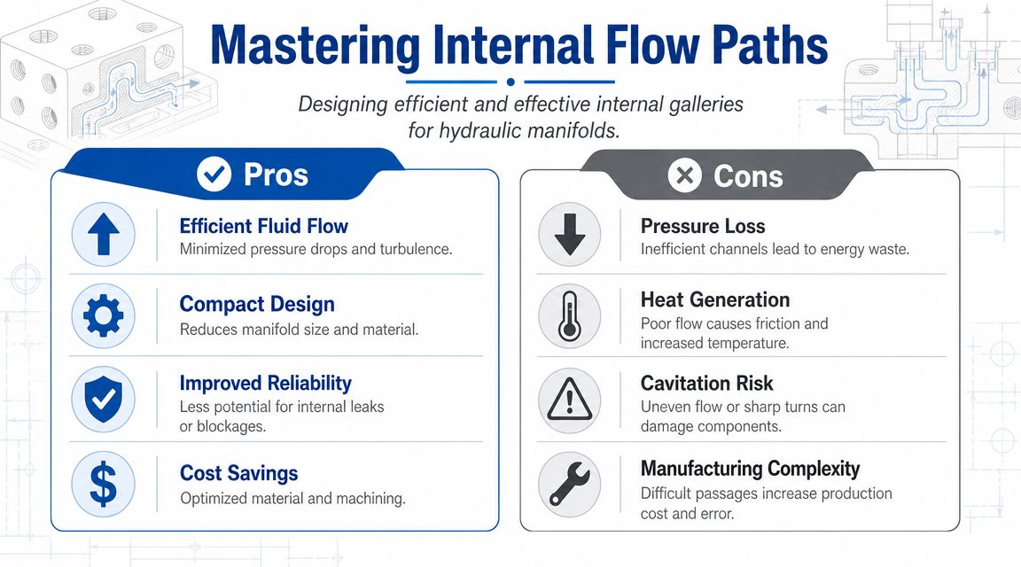
Internal flow layout should follow the actual job of the circuit, not the neatest cavity pattern in CAD. Oil will always take the easiest route available, so every unnecessary turn, drilled intersection and sudden bore change shows up somewhere else as heat, lag, noise or erratic control.
The layouts that hold up well in UK mobile and industrial service tend to share a few practical traits:
- Keep the high-flow routes short and direct. Long, indirect galleries add pressure loss and make troubleshooting harder.
- Control changes in direction and section. Tight turns and abrupt diameter changes disturb flow and can upset proportional or load-holding behaviour.
- Separate dirty work from sensitive control. Relief discharge, frequent dump flow and fine pilot signals should not be fighting for space in the same area of the block.
- Arrange cavities to suit both flow and machining. A logical sequence reduces awkward cross-drillings and leaves more usable material where it matters.
Main pressure and tank galleries work like trunk routes. Pilot lines and signal passages are smaller side routes. Problems start when a main route gets necked down to suit packaging, or when a pilot drilling sits too close to a high-flow return passage that keeps pulsing.
Pressure drop is usually drawn into the block
Pressure drop inside a manifold is rarely a surprise if the galleries have been sized and routed properly. It is more often the result of design compromises that were accepted too early. Common examples are undersized drillings, poor alignment between cavity ports and cross-holes, and flow being sent across the block because there was space left there.
Some compromises are justified. A more compact block may save envelope and mounting space on a mobile machine. A shorter block can also cut pipework cost on industrial equipment. But if that compactness forces small galleries, thin wall sections or repeated changes in flow direction, the block will give the cost back through heat generation, slower response and difficult commissioning.
A manifold can be machined perfectly and still perform badly because the internal route was wrong from the start.
Geometry sets performance and pressure integrity
Internal layout is not only a flow question. It is also a pressure boundary question.
For equipment used in the UK, designers need clear evidence that the manifold body, materials and geometry are suitable for the intended pressure duty. That includes what is left between intersecting drillings, cavity edges and outer faces. An article by HI-DES on hydraulic manifold design basics and pressure equipment requirements describes why documented pressure rating and material justification matter under this regulatory framework.
On the drawing, a cross-drilling might look harmless. On the finished block, two holes set too close together can leave a weak ligament that distorts under pressure or gives trouble later in fatigue service. I have seen blocks that passed an initial pressure test but still caused problems in the field because the geometry left too little material around a cartridge cavity shoulder or a gauge port.
Checks that catch expensive mistakes
Before release, the internal layout should be reviewed as a manufacturing part and as a hydraulic part. Both matter.
-
Main working flow paths
Confirm the highest-flow services have the least restrictive route through the block. -
Drilling intersections and wall thickness
Check material left between galleries, cavities, mounting features and external faces. -
Relief discharge and return routing
Ensure dumped flow returns cleanly without disturbing adjacent control functions. -
Pilot passage stability
Protect small control lines from pressure fluctuation, cross-talk and contamination traps. -
Machining practicality
Review whether the drilling plan is realistic, repeatable and easy to inspect on the shop floor. -
External connection reality
Make sure the best internal route does not create an impossible hose run, fitting clash or test point position outside the block.
Good internal flow layout rarely looks clever. It looks settled, well judged and easy to manufacture. That is usually the sign that the design work has been done properly.
Real-World Operational Considerations
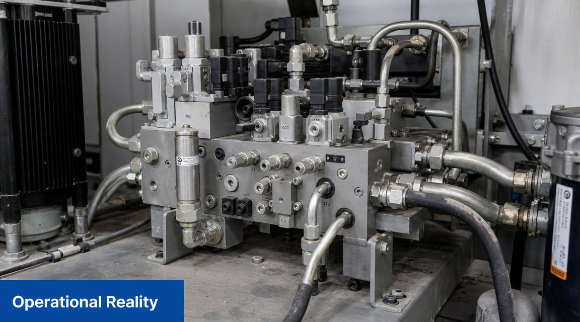
A manifold can be hydraulically correct and still fail on the machine because someone ignored heat, mounting or sealing detail.
Heat and valve placement
The block itself acts as a heat sink, but only up to a point. If relief valves or proportional elements are concentrated in one area with poor airflow around the manifold, local temperature climbs and seals suffer first. That's often missed on enclosed industrial equipment and compact mobile machines where the manifold gets tucked into the only available space.
Place heat-generating functions where the block can shed heat and where adjacent coils, seals and hoses won't sit in a hot pocket. If the machine runs long duty cycles, this becomes much more important than it looks on the drawing.
Mounting affects reliability
Mounting holes are easy to underestimate. They must secure the block properly without colliding with galleries, weakening critical sections or forcing awkward installation positions. On mobile machinery, poor support shows up as vibration fatigue, cracked fittings and damaged coils. On industrial systems, it often appears as gradual loosening, distorted pipe alignment and hard-to-trace seepage.
A few practical checks save pain later:
- Support the mass properly. A heavy manifold hung off pipework or valve bodies will move.
- Allow tool access. If a technician can't reach a fixing bolt or a cartridge hex, service time climbs immediately.
- Respect hose routing. Tight bends and twisted fittings add strain that the manifold itself ends up carrying.
Sealing is a system issue
Leaks are rarely caused by “bad luck”. Most stem from poor surface condition, mixed standards, wrong seal material, damaged installation practice or valves mounted where contamination falls straight into open cavities during service.
The best sealing strategy is boring and disciplined. Keep cavity specifications exact. Match seals to the fluid and operating temperature. Avoid unnecessary adaptors. Make sure service access allows clean replacement rather than rushed replacement.
A dry manifold usually starts with good design, not sealant.
This is also where UK environmental conditions matter. Outdoor equipment sees water, fertiliser, road dirt, washdown and corrosion exposure. Material choice helps, but cleanability and sensible external layout help just as much. If ports collect dirt and cartridges are buried where nobody can clean around them, field reliability won't stay good for long.
From CAD to Reality Manufacturing and Validation
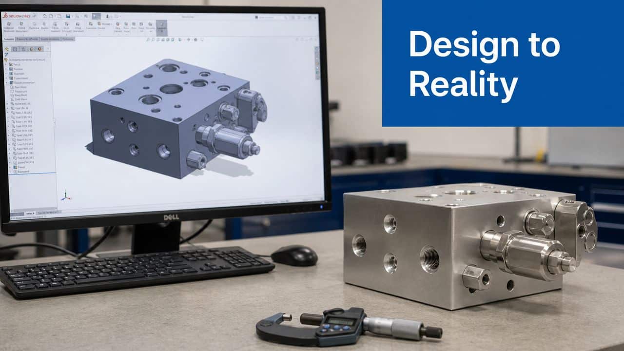
A manifold file isn't finished when it looks neat on screen. It's finished when production can machine it unambiguously and test it without guessing what the designer meant.
British hydraulic engineering has long favoured manifold integration to reduce leak points and assembly complexity. The move from scattered plumbing to standardised modular control blocks began in the 1970s, and that principle still underpins reliable UK hydraulic systems in sectors such as agriculture and construction, as described in this overview of why hydraulic manifolds remain so fundamental. The digital tools are more advanced now, but the objective is the same. Fewer leak paths, cleaner installation, better serviceability.
Give the machinist a complete instruction set
A proper manufacturing pack should include more than a 3D model. It needs a clear drill list, cavity references, thread details, depth control, plugging requirements, datum strategy and notes on any features that must be machined in a particular order.
If the production team has to infer whether a drilling breaks into another passage or stops short, the design handover is incomplete. That's where costly scrap often begins.
Useful release information usually includes:
- Connection lists that identify every hydraulic path clearly
- Drill lists with diameters, depths and intersecting features
- Cavity call-outs tied to exact manufacturer data
- 2D drawings for critical dimensions, threads and tolerances
- 3D CAD files for orientation and assembly reference
Validation is not optional
Once machined, the manifold still has to prove itself. Pressure testing, cleaning and functional checks are what separate a finished component from an unfinished risk.
Pressure testing should confirm that the block contains pressure safely and that intersecting galleries, plugs and cavity forms seal correctly. The block then needs flushing and cleanliness control so machining debris doesn't become the first contaminant in the finished hydraulic system. After that, the assembled manifold should be function-tested against the circuit intent, not merely checked for leaks.
A useful visual reference for that digital-to-physical transition is below.
If a manifold only works after the test technician “knows its quirks”, the design still isn't right.
Common Pitfalls and Real-World Application Insights
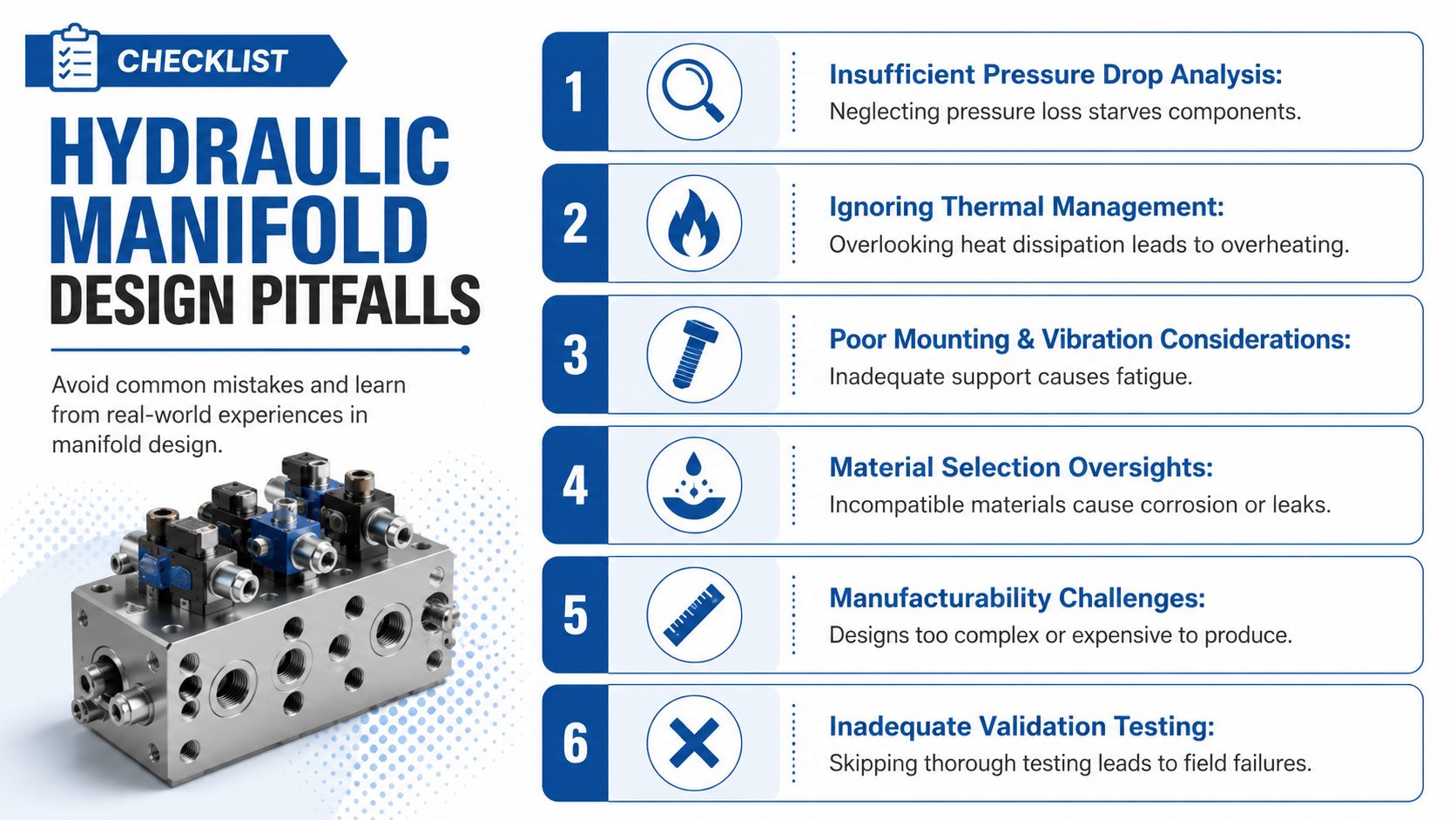
The mistakes that hurt most in hydraulic manifold design are usually ordinary ones. Not dramatic. Just expensive.
What goes wrong most often
I see the same handful of problems repeatedly:
- Main galleries sized by guesswork. The circuit may function, but the machine feels lazy, hot or noisy because the oil is being throttled internally.
- Ports placed for symmetry, not access. The drawing looks tidy. The fitter then can't get a hose end or torque tool onto the connection.
- Wrong cavity family specified. This can scrap the block outright because close-enough cavity geometry often isn't usable.
- No allowance for machining realities. Cross-drill intersections, tool approach and plug locations weren't considered early enough.
- Service items buried in the assembly. Coils, cartridges or test points sit behind guards, pipework or structural members.
None of those failures are exotic. They come from rushing layout before the function is fully locked down.
A mobile example
Take a compact log splitter or small agricultural attachment. Space is limited, hoses are vulnerable, and the temptation is to make the manifold very small. If the pressure gallery is pared back too far and the return route is forced through awkward turns, the assembly may still operate, but it won't feel clean in use. Heat builds faster, response becomes less consistent, and what looked like a compact solution becomes a troubleshooting exercise.
The better answer is often a slightly larger block with cleaner galleries, easier ports and more sensible cartridge spacing. It uses a bit more material, but it saves time in build and trouble in service.
An industrial example
On an industrial press brake or clamp circuit, the risk is different. Designers often prioritise a compact face layout for neat pipe runs, then crowd cavities together and leave little room for tools or for safe wall sections between passages. The machine may commission correctly, but routine maintenance becomes awkward and any later change is painful.
That's why manufacturability and serviceability have to stay in the same conversation as hydraulic performance. A manifold that only suits the first installation isn't a strong design.
Electrohydraulics raise the standard
A key challenge for UK designers is sizing manifolds for digital and electrohydraulic systems. Many guides stop at basic layout, but internal flow losses and leakage can materially affect the control performance and energy efficiency of fast-switching valves, which matters as UK manufacturing faces pressure to reduce energy use and emissions, as noted in this discussion of digital hydraulics and manifold design considerations.
That changes the design priority. Internal volume, leakage paths and pressure-drop behaviour matter even more when the valve is expected to switch quickly and repeatedly. A manifold that was acceptable for a straightforward on-off function may be completely unsuitable for high-response electrohydraulic control.
Conclusion Your Partner in Hydraulic Design
Strong hydraulic manifold design comes from discipline. Define the circuit properly, choose components before metal, lay out the flow paths with pressure and service in mind, and validate the finished block like it matters, because it does. The best manifolds aren't just compact. They're buildable, testable, maintainable and appropriate for the machine they serve.
If you need support with a bespoke manifold, valve selection, power pack integration or a difficult redesign, speak to people who deal with these trade-offs every day.
If you need help with hydraulic manifold design, bespoke power solutions or component selection, contact MA Hydraulics Ltd. Phone 01724 279508 today, or send us a message.
