
A lot of people land on pressure relief valve sizing after a failure. Not always a dramatic one. Sometimes it's a hose that split on a telehandler, a manifold block that keeps weeping around a cartridge cavity, or a power pack that runs fine until a cold start and then starts barking the relief. The valve is there, the schematic shows one, and everyone assumes the protection side is covered.
It often isn't.
In UK mobile and industrial hydraulics, the trouble usually isn't that someone forgot to fit a relief valve. It's that the valve was chosen from habit, copied from a previous build, or fitted without enough thought to flow, pressure override, inlet line losses, outlet backpressure, fluid condition, and the way the machine operates in service. That's where expensive faults begin.
The Critical Role of Correct Valve Sizing
A dumper starts cleanly on a winter morning, the operator tips into a hard stop, and the pressure spike goes somewhere the designer did not intend. The relief valve is fitted, the set pressure looks right on paper, and the failure still turns up in a hose, a manifold seal, or the pump case.
That is what poor sizing looks like in service.
In UK mobile and industrial hydraulics, correct relief valve sizing is about more than picking a cartridge with the right pressure range. The valve has to open where the circuit needs protection, pass enough flow under operational duty, and stay stable with the pipework, fluid condition, and backpressure the machine encounters. Get that wrong and the relief valve stops protecting the system in any meaningful way. It shifts the stress somewhere less visible.
What goes wrong in practice
The failure mode changes with the application. On mobile plant, repeated shock loads and fast actuator reversals can push a marginal valve into heavy override, which is where burst hoses, cracked fittings, and cavity leakage start to appear. On industrial power packs, the more common pattern is chronic operation across relief. Oil temperature climbs, pump life drops, and energy is wasted as heat.
I see one mistake more than any other. Engineers treat the relief valve as a pressure setting instead of a flow-handling safety component.
A valve that cannot pass the available pump flow quickly enough will let pressure rise well above the intended protection point before the circuit settles. A valve that is too large for the actual duty can hunt and chatter, especially if the installation adds inlet losses or outlet backpressure. Neither condition is benign. Both shorten component life, and both make fault-finding harder because the valve is technically present but not doing the job reliably.
Practical rule: A relief valve protects the system only when its pressure setting, flow capacity, and installation details suit the real machine.
That last point gets missed in workshops. Pipe runs, adaptors, discharge routing, contamination level, oil viscosity at cold start, and the speed of the pressure event all affect how the valve behaves. The catalogue figure is only part of the story. If you need to verify the pump side before any sizing work, use a proper hydraulic flow rate calculation method rather than the nominal flow written on an old build sheet.
Why this matters in UK applications
UK installations also bring a compliance angle that generic sizing guides often skip. On industrial systems, the valve setting must sit within the pressure limits of the weakest rated component in the protected section, and the installed arrangement has to satisfy the relevant machinery and pressure safety requirements. On mobile equipment, the same principle applies in practice even where the packaging is tighter and the operating cycle is harsher. Relief protection has to match the actual pressure envelope of hoses, cylinders, manifolds, test points, and auxiliary circuits, not just the pump nameplate.
Standards matter, but so does judgement. BS and EN requirements set the framework. The machine still has to survive cold oil, aggressive duty cycles, poor access for pipe routing, and maintenance realities on UK sites.
Correct sizing is what keeps the relief valve from becoming the hidden cause of overheating, instability, nuisance failures, and avoidable safety risk.
Gathering Your Essential Sizing Inputs
A relief valve that looks right on the schematic can still be wrong on the machine. I see that most often when the valve has been sized from a nominal pump figure and a guessed pressure setting, with no check on what the circuit does at end of stroke, on cold start, or during a blocked-line event.

Start with the figures that define the real relief event
Get the maximum flow that can reach the valve during the fault or operating condition you are protecting against. On a fixed displacement unit, that may be close to pump output. On a variable pump, load-sensing system, or branch-protected circuit, it may be something else entirely. Accumulators, overrunning loads, and regeneration circuits can all change the number. If the hydraulic side needs checking first, use a proper hydraulic flow rate calculation method rather than relying on an old build sheet.
Then pin down the highest legitimate working pressure for that protected part of the circuit. Use the schematic, component ratings, and test data. Workshop memory is not enough. In UK industrial and mobile systems, this matters because the relief setting has to protect the weakest rated component in that section, not the part with the highest pressure stamp.
Record pressure properly
One pressure number does not size a relief valve.
You need three separate values:
- Maximum required working pressure for the actuator, motor, or clamping function
- Cracking pressure where the valve first starts to lift
- Full-flow relief pressure where the valve is passing the required discharge flow
Those figures describe how the valve behaves under load, which is what matters in service. A valve that starts to crack at an acceptable pressure can still let the circuit run too high before it reaches full relieving capacity. That is one of the common causes of heat, noise, and nuisance operation on mobile plant and compact industrial power packs.
For the pressure setting itself, use the valve maker's data and the system design limits, then verify the setting on the machine. MA Hydraulics covers the difference between opening pressure and relief behaviour in its guide to hydraulic pressure relief valves.
Fluid data changes the sizing result
Relief capacity depends on the fluid you are passing through the valve, not a generic oil value copied from another project.
Collect these inputs before you size anything:
- Fluid type, such as mineral oil, synthetic fluid, or water-based fluid
- Viscosity range, especially cold-start and hot-running conditions
- Density or specific gravity
- Specific heat, if thermal relief is part of the duty
- Operating temperature at the point relief may occur
Cold oil is usually where mistakes show up first. A valve that behaves acceptably on warm test oil can react very differently on a January start-up in an outdoor UK yard, especially with long inlet runs or small-bore manifolds.
Include the installation details, not just the valve data
Sizing done from catalogue pages alone misses the installation losses that decide whether the valve stays stable and repeatable.
At minimum, confirm:
- Backpressure at the outlet, including what the return line creates during discharge
- Inlet line arrangement, including fittings, reducers, hose length, and any manifolding restrictions
- Valve orifice and model data, if you are checking an existing installation
- Fluid state, because liquid, gas, and mixed-phase duties are sized differently
This point matters in UK practice because installation constraints are often what upset an otherwise correct selection. Mobile equipment gives you limited space and awkward routing. Older industrial systems add adaptors, isolation hardware, and return lines that were never designed around the current flow.
If you are working on compressed air or gas protection as part of a wider package, collect the receiver or vessel duty, compressor output, and pipework losses from the applicable standards and supplier data already used on the job. Keep that information with the hydraulic sizing notes. It avoids a common handover problem where the valve itself is adequate but the installed inlet or discharge arrangement is not.
Good sizing starts with accurate inputs. Get those right, and the calculation stage becomes a check of engineering judgement rather than an attempt to rescue bad assumptions.
Calculating the Required Valve Capacity
A relief valve usually gets tested on the worst day, not on the drawing board. A telehandler hits the end of stroke in winter with cold oil, or an industrial power pack sees a dead-headed actuator after a maintenance change. If the valve cannot pass the fault flow at the installed pressure, the numbers on the catalogue page do not help.
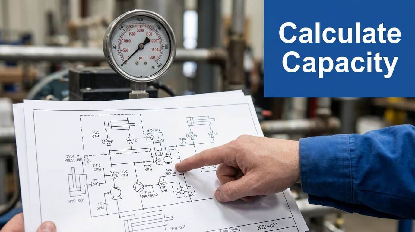
Start with the flow that can actually reach the valve
For many hydraulic systems, the first-pass relieving flow is the pump's maximum delivered flow at the speed the prime mover can really achieve. That is only the starting point. On mobile plant, overrunning loads, regeneration circuits, or accumulator discharge can add flow during the event. On industrial manifolds, the valve may protect only one branch, so sizing it to full pump flow can give poor control and unnecessary heat.
The valve must pass the required flow at relief conditions, and the selected capacity must not be so far above duty that the valve becomes unstable. Under EN 13136, the actual relieving capacity Qm must be at least equal to the required capacity Qmd, and should not exceed five times the requirement, written as Qm ≤ 5 × Qmd (Henry Group pressure relief valve guide).
That upper limit matters in practice. An oversized valve can chatter, run hot, and wear the seat early. I see this regularly on older UK industrial units where someone fitted the largest cartridge that matched the cavity and assumed more capacity meant more protection.
Capacity calculations depend on the valve data you are allowed to use
Once the required relieving flow is clear, convert that duty into the orifice area or rated valve size using the coefficient basis that matches the device. If the manufacturer has certified flow data, use that. If not, preliminary sizing relies on published coefficients, and you need to be honest about what is only an estimate.
For preliminary liquid-service sizing, Kd is often taken as 0.65 for conventional valves (AIChE article on relief device sizing coefficients). For some general required-area calculations in the same published guidance, 0.975 is used as part of the relief area calculation basis (AIChE article on relief device sizing coefficients)).
Those assumptions are not interchangeable. Use the wrong basis and the calculated area moves enough to push you into the wrong valve size, especially where pressure override is already tight.
A practical check on a 210 bar system
Take a common UK industrial power pack set around 210 bar. A 7.5 kW motor still does not tell you the relief duty on its own. You need the pump displacement, real motor speed, and any condition that can add transient flow.
Use a straightforward calculation path:
- Confirm the maximum pump flow at the actual running speed.
- Confirm the pressure at which the valve must start to open, and the pressure at which it must pass full fault flow.
- Check oil temperature and viscosity at the operating condition you expect during relief.
- Apply the correct coefficient basis or manufacturer-certified curve for the valve style.
- Compare the result against the maker's pressure-flow data, not only the nominal set-pressure range.
If you need to verify the pressure side before fixing the setting, use a proper hydraulic pressure calculation guide and check force and area from the actual cylinder geometry, not workshop shorthand.
One more practical point. Cost should sit well behind duty and stability. Market prices move, and imported listings often ignore UK support, seals, and certification. For mobile fleets, parts commonality still matters, so it is worth checking whether the selected valve shares service kits with the rest of the machine. The Woolpit Truck Repairs parts guide is a useful reminder that availability and downtime costs often outweigh the purchase price of the valve body.
| Check point | What you confirm | Why it matters |
|---|---|---|
| Required relief flow | Maximum flow that can reach the valve during the fault | Sets the minimum capacity |
| Pressure basis | Crack pressure, full-flow pressure, and allowable override | Prevents nuisance opening and under-relief |
| Coefficient or certified data | Preliminary coefficient basis or manufacturer-tested curve | Changes the calculated area and valve size |
| Oversizing limit | Capacity kept within the applicable standard guidance | Reduces chatter and poor repeatability |
| Installed condition | Real inlet and outlet losses during discharge | Confirms the valve will achieve its rated duty on the machine |
A relief valve is sized on paper, but it survives or fails in the installation. The calculation only counts if the fitted valve can pass the required flow at the pressure the system will really see.
Selecting the Right Pressure Relief Valve
Once you know the duty, the next decision is valve type. The choice of valve type often determines whether a lot of service problems are either avoided or built in from day one. Two valves can share the same nominal pressure range and still behave very differently on the machine.
Direct-acting and pilot-operated behave differently
Direct-acting valves are mechanically simpler. They usually respond quickly and suit compact circuits, mobile equipment, and branch protection duties where simplicity matters. Pilot-operated valves are often the better choice when you need steadier behaviour at higher flow, lower override, or tighter control around the set point.
| Feature | Direct-Acting Valve | Pilot-Operated Valve |
|---|---|---|
| Operating principle | Spring acts directly on the main element | Pilot stage controls the main stage |
| Typical use | Compact mobile circuits, simple protection duties | Higher-flow systems, steadier industrial duties |
| Response character | Fast and straightforward | More controlled once correctly applied |
| Sensitivity to contamination | Usually easier to understand in dirty service, but still needs clean oil | Pilot passages demand careful cleanliness |
| Pressure override | Often higher as flow rises | Usually lower than direct-acting alternatives |
| Packaging | Compact and simple | Larger and more complex |
For many CETOP-based industrial manifolds, a direct-acting valve works well if the flow is moderate and the installation is clean. On larger power packs or systems with wide flow variation, pilot-operated designs often give better pressure control.
Material and seal choices matter more than catalogues suggest
A steel-bodied valve is common for standard hydraulic oil service. Stainless steel becomes relevant when the environment, washdown conditions, or the fluid itself justifies it. Seal choice matters just as much. NBR may be fine for one oil and temperature range, while other fluids or hotter duties may push you towards a different elastomer.
This is one area where experience beats assumptions. If the machine lives outdoors, sees contamination, or works in agriculture, quarrying, or food-adjacent service, the environment starts influencing valve life almost as much as the nominal pressure does.
If you also deal with vehicle and plant repair, the wider parts-specification mindset in the Woolpit Truck Repairs parts guide is worth a look. It's useful because the same rule applies across hydraulics and heavy vehicle maintenance. Correct component matching on paper saves a lot of downtime in the yard.
Read the data sheet like an engineer, not a buyer
The pressure range on the front page isn't enough. Look for:
- Pressure-flow curves that show what happens as the valve approaches full flow
- Permitted flow range for the actual model and cavity
- Port sizes and mounting options
- Backpressure limitations
- Seal and body material details
- Adjustment range and factory setting notes
One option when you need cartridge, inline, CETOP directional, proportional, modular, or bespoke power-pack related support is MA Hydraulics Ltd, which supplies hydraulic components and application advice for UK mobile and industrial systems. The important part isn't the brand name on the box. It's whether the selected valve's curves and materials match the duty.
Don't select a relief valve by thread size and pressure range alone. Select it by behaviour under flow.
That's the difference between a machine that stays predictable and one that keeps coming back with “intermittent” pressure faults.
Common Sizing Pitfalls and Installation Best Practices
A common failure sequence on a UK machine goes like this. The valve size looks right on the worksheet, the unit is built under time pressure, then someone fits the relief valve where it physically fits rather than where the circuit needs it. Add a tight inlet run, a reduced fitting, or a lazy tank return, and the valve that looked fine on paper starts chattering, running hot, or opening unpredictably.
Oversizing creates control problems
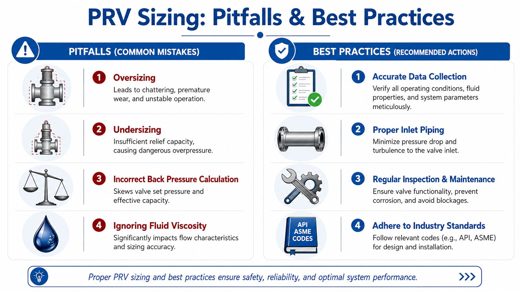
Engineers and fitters often treat a larger relief valve as extra safety. In practice, oversizing can make the system less stable, especially on mobile plant and smaller industrial power packs where flow changes quickly and pipework is rarely ideal.
As noted earlier, EN 13136 places a limit on how far actual relieving capacity should exceed the required relieving capacity. That matters because an oversized valve can cycle badly at real operating flow, batter the seat, and produce pressure behaviour that sends fault-finding in the wrong direction. I have seen this blamed on pumps, proportional valves, contaminated oil, and even cylinder seals when the underlying issue was a relief valve selected too far above duty.
Installation usually decides whether the valve behaves
Poor inlet and outlet pipework ruins good valve selection. The recurring field faults are familiar. A relief valve mounted too far from the protection point. An inlet necked down to suit what was on the shelf. A discharge line that looked acceptable until the machine spent time at full bypass and backpressure changed how the valve opened.
On hydraulic systems used in UK industry and mobile equipment, the practical rule is straightforward. Keep the inlet run short, straight, and at least as large as the valve connection. Keep the outlet free enough to pass full relieved flow without creating avoidable backpressure. If either side is compromised, expect instability, noise, heat, and short valve life.
That is why installation checks matter as much as sizing maths.
The field mistakes that keep coming back
-
Poor practice: Fitting the valve at the easiest manifold port or pipe tee, even though it is well away from the component being protected.
Better practice: Mount it as close as practical to the protection point so the valve sees the actual system pressure, not a delayed or damped version of it. -
Poor practice: Using reducers, swept hose routes, or multiple adaptors on the inlet because the thread forms happen to match.
Better practice: Treat the inlet as a priority line. Keep it direct, keep fittings to a minimum, and avoid any reduction that encourages pressure loss or unstable opening. -
Poor practice: Assuming the tank return will cope because it is only a relief line.
Better practice: Check the whole discharge path under full relief flow. Long runs, small-bore hose, stacked fittings, and contaminated return filters all add backpressure. -
Poor practice: Using a larger spare valve because it is available and the cracking pressure range appears suitable.
Better practice: Match the valve to the calculated duty and the actual circuit behaviour, not just the port size and adjustment range.
For practical assembly checks, mounting detail, and pipework discipline, MA Hydraulics provides installation guidelines for hydraulic components that are useful when reviewing power packs, manifolds, and replacement valve layouts.
If a relief valve chatters, do not start by blaming the valve. Check the inlet run, the discharge path, and the actual installed duty.
Habits that prevent repeat faults
A few site habits save a lot of call-backs.
- Compare the schematic with the built machine: Late hose reroutes and adaptor changes often explain behaviour that the design office never intended.
- Inspect for contamination before commissioning: Dirty oil, jointing debris, and damaged seals change valve response and seat condition quickly.
- Listen during pressure testing: A clean relief event sounds controlled. Flutter, barking, or repeated snapping usually points to pipework or sizing trouble.
- Check hot-running behaviour, not just cold start-up: A valve that seems acceptable on cold oil can become unstable once viscosity drops and return flow rises.
- Treat mobile applications more harshly than the drawing suggests: Vibration, flexible hose movement, and shock loading expose weak installation practice faster than static factory plant.
A relief valve protects the system you built. In UK service work, that distinction matters more than many sizing sheets admit.
Ensuring Compliance and Final System Checks
A relief valve that looks right on the drawing can still fail the machine on site. The problems usually show up at commissioning. Hot oil, a restrictive return line, a gauge that has drifted, or a set pressure adjusted in haste can turn a sound sizing exercise into nuisance relief, unstable operation, or a system that no longer protects its lowest-rated component.
In UK industrial and mobile service, compliance is tied to what the installed system does. The valve setting, the verified relieving behaviour, the discharge arrangement, and the pressure limit of every connected component all need to agree with the design basis and the applicable BS or EN requirements used for the machine. Paperwork matters, but the machine test matters more.
What to confirm before handover
Commissioning checks should prove the valve protects the actual installation, not an assumed one.
- Verify the set pressure with calibrated test equipment: Check it on the machine, with the actual oil condition and a repeatable test method.
- Confirm the valve will pass the required flow: A valve that only cracks open at test pressure has not proved relief capacity.
- Check pressure stability through the relief event: Watch for hunting, chatter, or a pressure rise that suggests backpressure or poor flow path design.
- Inspect the discharge route and tank return arrangement: Relief flow has to leave freely without creating unsafe pressure build-up downstream.
- Check for leaks, body stress, and joint movement: These often show up once the circuit reaches full pressure and temperature.
- Record the final setting and test conditions: This gives maintenance staff a reference for later fault-finding and helps show due diligence.
Mobile equipment needs harsher judgement than a clean workshop test suggests. Vibration, hose movement, shock loads, and changing oil temperature expose marginal relief settings quickly. On industrial power packs, the common trap is assuming steady duty. In service, blocked coolers, altered line sizes, or replacement components can change the relieving conditions enough to matter.
The final check is simple. The valve must open at the right pressure, pass enough flow, stay stable, and leave the rest of the system within its rated limits. If any one of those points is uncertain, the job is still open.
If you need help with MA Hydraulics Ltd component selection, circuit review, or a practical second opinion on pressure relief valve sizing for a mobile or industrial system, phone 01724 279508 today, or send us a message via the MA Hydraulics Ltd contact page.
