

A machine stops halfway through a shift, the operator reports sluggish movement, and the first suspect is usually the filter element. On inspection, the element may be perfectly suitable. The actual problem is often the hydraulic filter mount behind it: the wrong circuit position, restricted access, a poorly set bypass valve, or a housing that can't be isolated safely.
That distinction matters on farm equipment, mobile plant and factory rigs alike. A mount holds the element, but it also contains pressure, directs flow, supports seals and determines what happens when contamination or cold oil increases restriction. Selecting it as a bracket with ports is how avoidable pump, valve and maintenance problems enter a system.
Why the Mount Matters More Than the Element
A blocked return filter is a familiar workshop fault. The indicator has changed, the machine has slowed, and the operator has brought it in for a quick element change. Yet the replacement element doesn't solve the issue if the mount is undersized, the bypass arrangement is unsuitable or the return line is routed through a housing that can't release pressure safely.
The element only performs within the conditions created by its housing. Flow direction, pressure class, seal compression, bypass behaviour and service access all depend on the mount. A fine element in a restrictive suction housing can starve a pump. A correctly rated return element in the wrong location can allow contamination to circulate through sensitive valves before the fluid reaches the reservoir.
Practical rule: choose the mounting position from the failure consequence first, then select the element and housing as a matched assembly.
British filtration engineering has a long pressure-control tradition. A sand filter was installed for public water treatment in Paisley, Scotland, in 1804, James Simpson developed a treated public water supply in London in 1829, municipal water filtration became obligatory across Britain in 1852, and an automatic pressure filter was invented in England in 1899. These milestones show why filtration is more than a consumable replacement task. The hardware that contains and directs the filter has always been part of the process.
The standard behind a defensible specification
For hydraulic filter elements, BS ISO 16889:2022 was published on 30 September 2022 and is the current UK implementation of ISO 16889. It specifies the multi-pass method for evaluating hydraulic filter-element performance under controlled contaminant loading, including particle capture expressed through beta ratios. The published BS ISO 16889:2022 document gives engineers a recognised basis for comparing an element rather than relying only on an imprecise nominal micron description.
The mount still needs checking against the element's rated flow, pressure, bypass arrangement and connection configuration. A performance claim is useful only when the element can operate in a housing that maintains sealing, avoids excessive restriction and remains serviceable throughout the machine's duty.
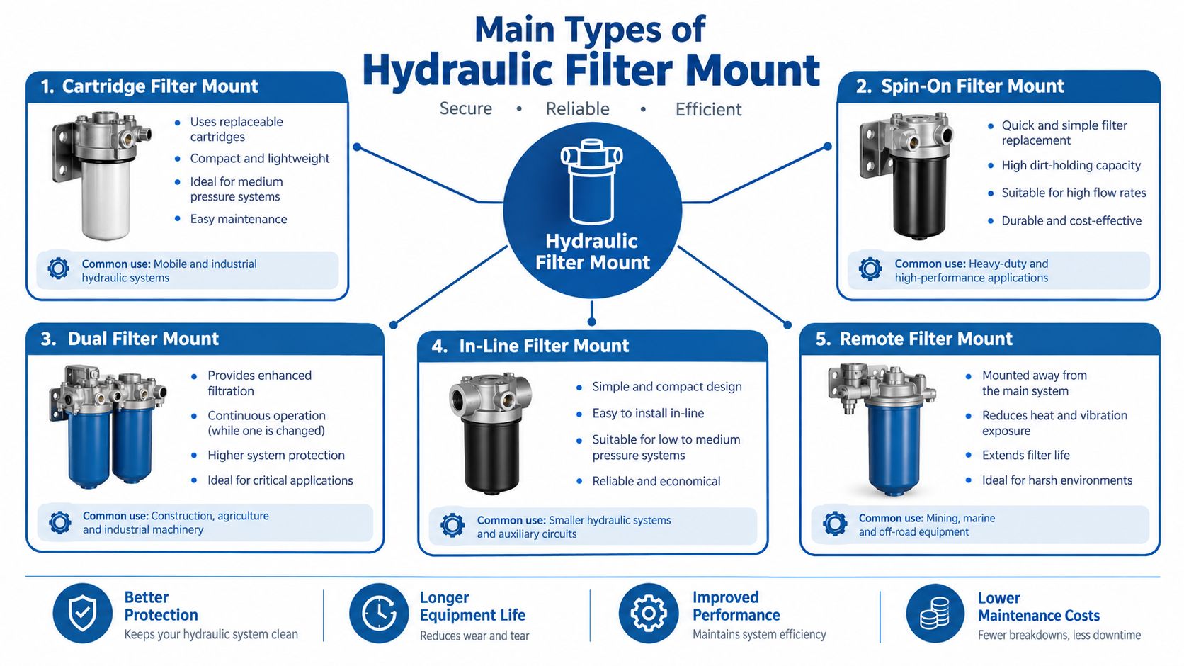
Main Types of Hydraulic Filter Mount
The circuit location determines what the mount protects and what a failure looks like. Read the hydraulic schematic from the reservoir towards the pump, then through the control section and back to the tank. That simple exercise normally reveals which mounting style is doing the most important work.
Suction mounts
A suction or in-line mount sits between the reservoir and pump, sometimes inside the tank and sometimes on the suction pipe. Its job is to stop larger debris reaching the pump, but it must impose very little restriction. A small or dirty suction element can reduce inlet conditions and contribute to cavitation, especially during cold starts when oil is more viscous.
Use a suction mount only when its flow capacity and pressure drop suit the pump inlet. A fine element that looks attractive on a catalogue page may be the wrong choice here. The safer arrangement is often a coarse protective screen combined with effective return or offline filtration elsewhere in the circuit.
Return-line mounts
The return mount filters oil as it travels back to the reservoir. It captures contamination generated during operation before that fluid mixes with the tank contents, making it a practical choice for many mobile and industrial circuits. The housing usually works at lower pressure than a pressure-line mount, but its bypass valve still needs careful consideration.
If the return filter blocks and the bypass opens too readily, contaminated oil can return unfiltered. If the bypass doesn't open when required, restriction can rise and affect actuator behaviour or create excessive back pressure. Port orientation, tank entry and drain-back space also matter.
Pressure-line mounts
A pressure mount sits downstream of the pump and upstream of sensitive valves or actuators. It needs a housing designed for the circuit's working pressure and pressure spikes, and it can protect precision components directly before contamination reaches them.
This protection comes at a cost. Pressure filtration usually demands a stronger, more expensive housing and closer attention to differential pressure. An undersized mount can waste energy, trigger the indicator unnecessarily or force the bypass to operate. For critical valve blocks and servo equipment, that trade-off may be justified. For a less sensitive circuit, a return or offline arrangement may offer better service economics.
Offline or kidney-loop mounts
An offline mount circulates a side stream through a dedicated filter, independently of the main working flow. It can gradually improve reservoir cleanliness without placing the full pump flow through the filter, making it useful for large tanks, continuous-duty machinery and systems where maintenance access is planned around a separate circuit.
This arrangement doesn't replace correct protection at a vulnerable pump or valve. It complements the main circuit by controlling background contamination and allowing filtration to continue without changing the primary flow path. For a practical view of housings and mounting formats, compare the hydraulic filter housing range.
Matching Filter Elements and Bases to the Mount
A filter element, head or base and housing should be specified as one assembly. Treating them as interchangeable parts often produces a connection that fits physically but fails on flow, pressure, seal material or indicator compatibility.
A spin-on cartridge is convenient for routine service because the element and casing are replaced together. That reduces handling during a change, but it can increase waste and restrict cross-referencing if the thread, seal and bypass arrangement aren't identical. A replaceable element inside a reusable bowl gives more flexibility and lets the technician inspect the housing, although it demands better cleaning discipline and careful seal installation.
Read the datasheet as a circuit document
Start with rated flow in litres per minute, maximum working pressure in bar, fluid compatibility and the manufacturer's stated differential-pressure behaviour. Then check the connection type, port size, mounting pattern, element length and removal clearance. A nominal micron rating alone doesn't tell you how the element behaves under controlled contaminant loading, so look for a traceable performance claim based on BS ISO 16889:2022 or an equivalent method.
The British Fluid Power Association lists BS ISO 16860:2005 for testing differential-pressure devices. That is directly relevant when the hydraulic filter mount has a clogging indicator or bypass-monitoring arrangement, as shown in the BFPA fluid power standards listing.
Compare the usual pairings
| Mount Type | Typical Element Style | Base or Head Style | Key Checks |
|---|---|---|---|
| Suction | Coarse screen or low-restriction element | In-tank strainer or in-line head | Pump inlet conditions, flow capacity, collapse resistance and cleaning access |
| Return | Replaceable element or spin-on cartridge | Tank-return head with bypass and indicator options | Rated return flow, bypass setting, tank connection, seal material and cold-oil restriction |
| Pressure | High-pressure replaceable element | Reinforced head with threaded or flanged ports | Working pressure, pressure spikes, beta performance, indicator setting and port configuration |
| Offline | High-efficiency replaceable element | Dedicated side-stream filter head | Kidney-loop flow, pump compatibility, continuous duty, isolation and drain provisions |
The hydraulic filter base selection should follow the same logic. Confirm whether the base accepts the intended element, whether the seal sits correctly and whether the indicator or bypass can be serviced without disturbing the rest of the circuit.
Don't substitute imperial-only catalogue descriptions for clear UK specifications. For trade purposes, dimensions, port sizes, pressure ratings, flow rates and weights should be presented in metric terminology, with any non-metric equivalent secondary, in line with UK measurement guidance.
Installation and Orientation Best Practice
Installation starts before the spanner touches the housing. A hydraulic line can retain energy after the pump has stopped, particularly where accumulators, trapped fluid or supported loads are present. HSE guidance identifies shut-off and drain provisions as features that support safe maintenance, while HSENI instructs personnel to release stored energy and depressurise vehicle hydraulic systems before repair, as set out in the HSE fluid power safety guidance.
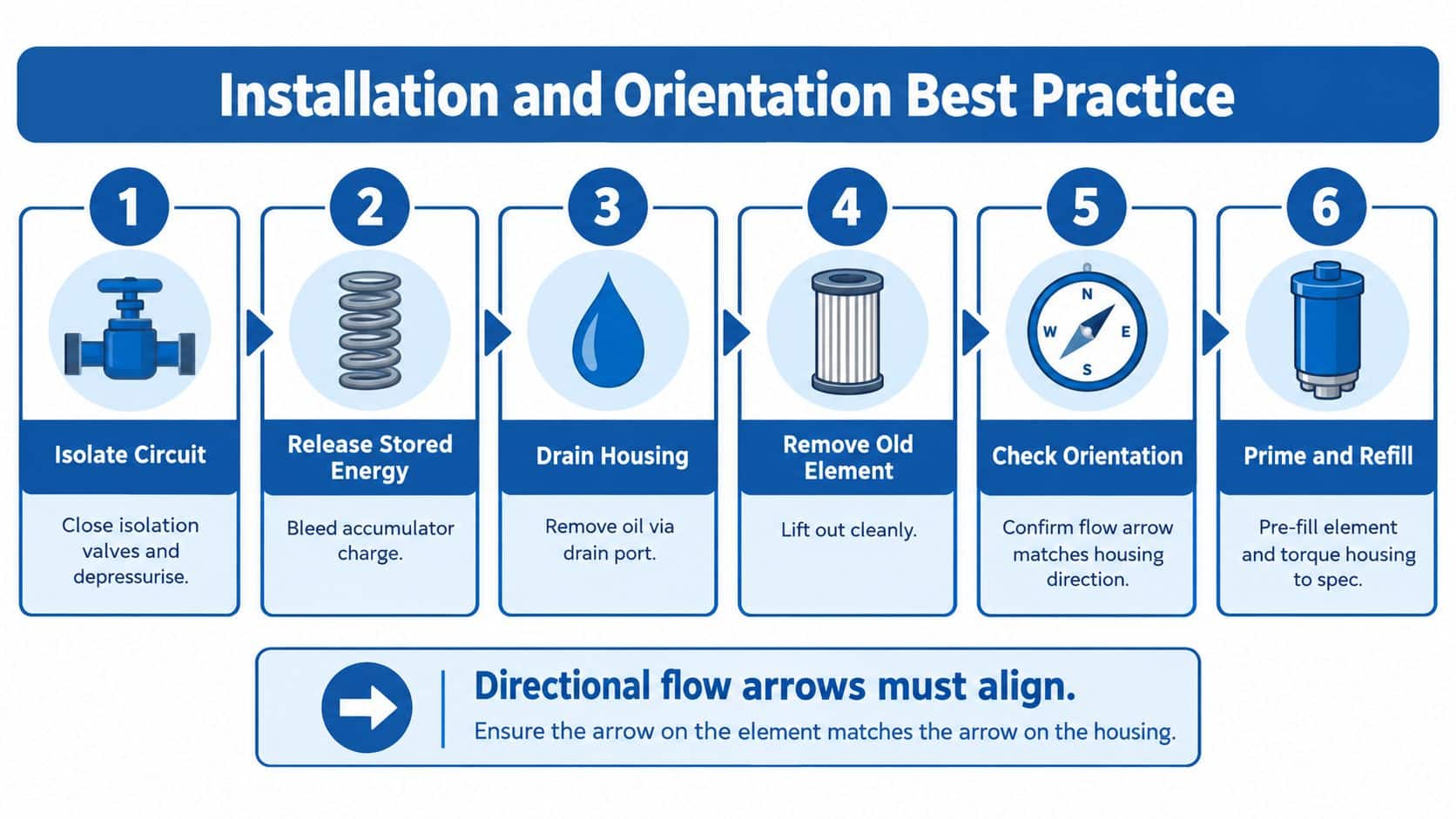
Use a controlled sequence
- Isolate the circuit. Close the correct isolation valves and stop the machine according to its maintenance procedure. Support any suspended or raised load mechanically.
- Release stored energy. Bleed accumulator charge where the circuit permits, move controls only through the approved safe procedure and confirm that pressure has fallen at the correct test point.
- Drain the housing. Use the drain provision rather than allowing oil to spill across the machine. Capture the fluid in a suitable container.
- Remove the old element. Keep dirt away from the open head, inspect the bowl and remove the seal without scoring the sealing face.
- Check orientation. Match the arrow on the head to the actual flow direction. An upside-down head can invert the bypass arrangement and allow unfiltered oil to circulate when the valve should protect the circuit from excessive restriction.
- Prime and refill. Pre-fill the element where the design and fluid cleanliness procedure allow it, lubricate seals with clean system fluid, seat the element squarely and tighten the housing to the manufacturer's specified metric torque.
Don't invent a torque value when the component maker hasn't supplied one. Thread size, seal design and housing material change the correct setting, so the manufacturer's value takes priority over a generic workshop habit.
Repressurise with checks in place
After installation, open isolation gradually and watch for leaks at the head, bowl, drain and ports. Verify the indicator, confirm that the bypass arrangement is correctly fitted and check the filter differential pressure under normal operating conditions. Leakage must be detected with an appropriate method, never by placing a hand near a suspected high-pressure jet.
For an accessible inline arrangement, the inline hydraulic oil filter range provides a useful reference point for comparing head formats and service arrangements.
Space, Access and Indicator Placement
The first filter change exposes poor mounting design. A housing that looked compact during assembly can become impossible to remove once hoses, guards and chassis rails are in place. Allow enough room to withdraw the element vertically or unscrew the cartridge without twisting adjacent pipework.
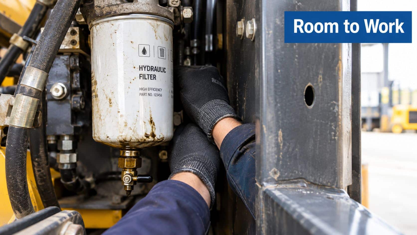
The mount should also support clean handling. Provide a drain route or drip tray, keep the open housing away from mud and swarf, and avoid positioning the element where a technician has to lean across moving or hot components. Hose runs should have enough flexibility for vibration without loading the ports sideways. A rigid pipe pulling on the head can turn a small installation error into a recurring seal leak.
Make restriction visible
A clogging indicator works only when someone can see and interpret it. On mobile plant, position the indicator where the operator or service technician can inspect it without dismantling guards. On factory equipment, connect an electrical switch or visual indicator to a panel where the maintenance team can act before the bypass becomes the normal flow path.
Cold oil complicates diagnosis. A healthy element can show higher differential pressure during a cold start because viscosity increases, while a warm reading under equivalent flow gives a different picture. Record normal differential pressure at operating temperature and compare future readings under similar load and flow conditions rather than replacing elements solely because of a brief cold-start indication.
The UK manufacturing downtime and maintenance discussion reports more than £80 billion in unplanned downtime across the UK and EU in 2025, and says predictive-maintenance adoption fell from 30% to 27% between 2024 and 2025. Those figures reinforce a practical point: a visible, usable indicator is valuable only when the team has a defined response and records the operating conditions behind it.
The embedded maintenance video should be checked at its intended display size and on smaller screens, particularly because incorrect frame sizing can make installation details difficult to follow.
Add accurate alternative text to the image and verify every label for inlet, outlet, flow direction, seals, indicators and dimensions against the actual component. UK accessibility guidance says informative images and tables need contextually accurate alternative text, as set out in the government accessibility standards. Any essential specification shown in an image should also appear as normal page text.
Common Mistakes to Avoid
Many filter problems begin with a reasonable assumption: if the element fits the head, the installation must be acceptable. Hydraulic systems don't work that way. The circuit location, restriction path and failure consequence decide whether a mount protects the machine or creates a new fault.
Errors that return to the workshop
- Putting a return filter in the wrong part of the return circuit: If contaminated oil passes through valves before reaching the filter, those components remain exposed. Place the filter where it captures returning contamination before the fluid re-enters the reservoir, unless the circuit design requires another arrangement.
- Using a restrictive suction mount: A blocked or undersized suction filter can starve the pump. Select for low restriction and inspect inlet conditions rather than treating suction filtration like pressure filtration.
- Ignoring bypass cracking pressure: A bypass set too low can send dirty oil around a healthy element. A bypass set too high can create excessive restriction and reduce downstream flow. Confirm the setting against the housing and circuit design.
- Mounting the head upside down: The arrow may be overlooked, and the bypass or indicator may no longer operate as intended. Confirm orientation before tightening hoses.
- Relying on a fixed replacement interval: Dust, temperature and duty vary across agricultural and mobile work. A differential-pressure indicator can provide better evidence, provided the team understands cold-start readings and compares equivalent conditions.
- Checking leaks by hand: HSE warns that hydraulic injection injuries can occur at comparatively low pressures. Use suitable detection methods and depressurise before disturbing the mount.

A pressure-line filter isn't automatically a better filter than a return-line mount. It may protect a sensitive valve more directly, but it also adds a high-pressure housing, more demanding seals and a restriction path that needs monitoring. Conversely, a return mount may be entirely suitable where the main objective is to control reservoir contamination, not to provide final protection immediately before a precision component.
Keep the specification readable
Use millimetres, litres per minute, bar and kilograms as the primary units on drawings, labels and purchase orders. Imperial equivalents can be secondary where useful, but they shouldn't obscure the metric value required for a clear UK trade specification.
Fluid compatibility deserves the same care as the mount. If a maintenance team is comparing hydraulic and transmission applications, a resource such as AMT fluid specs explained can help clarify why fluid formulation and application should be checked rather than assumed from a familiar product name.
Images and videos need technical quality control too. Proofread wording embedded in diagrams, verify that arrows and port labels match the component, and check captions for terms such as bypass valve, return line, hydraulic fluid and pressure differential. Government guidance recommends accurate, synchronised captions and a transcript or equivalent written alternative where video carries essential information, as described in basic accessibility checking guidance.
Choosing the Right Mount for Your Application
Choose the mount from the duty, not from the cheapest element or the most convenient port thread.
For mobile plant, prioritise vibration resistance, service access, hose protection and an indicator that can be seen without removing guards. Agricultural equipment needs particular attention to dust ingress, intermittent operation and cold starts. A low-restriction suction arrangement can protect the pump, while return or offline filtration manages contamination without placing unnecessary restriction at the inlet.
Industrial machinery often benefits from a more deliberate monitoring arrangement. A pressure mount may suit sensitive valves, while an offline loop can maintain reservoir cleanliness during long operating periods. Use a fixed replacement interval only where duty and contamination are consistent. Where conditions vary, differential-pressure readings provide a more useful maintenance signal, provided readings are taken under comparable temperature, load and flow conditions.
Safe disposal belongs in the specification. The reusable mount can normally remain in service after inspection and cleaning, while the used element retains oil and must be handled separately. UK government guidance classifies oil filters as hazardous waste under code 16 01 07* and requires waste oil filters to be stored with secondary containment. For crushed and emptied filters using the T14 route, the guidance gives a maximum storage quantity of one tonne, as set out in vehicle and oily-waste classification guidance. Crushing isn't automatically permissible, so confirm the route, oil type, storage controls and licensed-waste arrangements before disposal.
For help matching a hydraulic filter mount to pressure, flow, element format, indicator arrangement and safe access, phone 01724 279508 today or send MA Hydraulics a message.
MA Hydraulics Ltd supplies hydraulic filter housings, bases and complete filtration assemblies for mobile and industrial equipment, with support for cross-referencing and application-specific component selection. Visit MA Hydraulics Ltd to discuss a mount that matches your circuit, operating conditions and maintenance requirements.
