
You've just fitted a replacement pump to an excavator after finding scoring on the old unit. The machine runs well, the oil looks clean in the reservoir, and the job is signed off. A few weeks later, the replacement pump is noisy, sluggish and heading back to the workshop. In my experience, that sequence usually points to contamination, not bad luck.
Why Filtering Hydraulic Oil is Your Best Reliability Investment
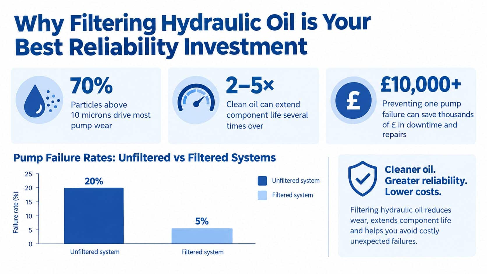
Hydraulic filtration controls the contamination that shortens component life and turns routine maintenance into pump, valve and actuator repairs. UK hydraulic-maintenance guidance attributes approximately 70–80% of hydraulic-system failures to particles, water, air or other contaminants in the fluid (UK hydraulic-system guidance). Contamination can enter during manufacture, transport, storage and filling, then increase through wear, seal degradation and reservoir breathing.
The overlooked point is oil transfer. New oil is not automatically clean enough for a precision circuit, and stored oil can collect particles or water. Before a top-up, clean the transfer container, inspect the hose and fittings, and pump the oil through a suitable filter rather than pouring directly from a drum or tote. Keep the transfer equipment capped between uses. Record the oil source and filtration work so an unexplained cleanliness result can be traced.
The installed system still needs protection. A return-line filter captures wear debris before it reaches the reservoir, while a pressure-line filter protects sensitive downstream components. Larger systems may benefit from an offline kidney-loop circuit that conditions the reservoir independently of machine operation.
Workshop rule: After a pump, cylinder or valve failure, investigate the oil, transfer equipment and surrounding circuit before installing the replacement.
Hydraulic oil contamination also creates an environmental risk. Offshore Energies UK reported that hydraulic oil accounted for 41% of unintentionally released oil in 2023, compared with diesel at 22% and crude oil at 16% (Offshore Energies UK environmental insight). Filtration reduces abrasive wear and supports seals and valves, but inspection, containment and planned maintenance remain necessary.
Understanding the ISO 4406 Particle Count Standard
You can't judge hydraulic cleanliness by looking into the tank. Oil may appear bright and clear while carrying particles small enough to score a cylinder surface, damage a pump's sliding surfaces or interfere with a servo valve.
ISO 4406 gives UK maintenance teams a measurable language for cleanliness. Laboratories count particles in three size bands, greater than 4, 6 and 14 micrometres, and report a three-part code such as 18/16/13 or 16/14/11 (UK hydraulic-system guidance). Each position corresponds to one of those particle-size bands.
A single code step represents a doubling or halving of the permitted particle-count range. Consequently, a one-code improvement isn't a minor visual refinement. It can substantially reduce the number of contaminants circulating through pumps, valves and actuators.
| Component type | Target ISO code |
|---|---|
| Servo valves | ISO 16/14/11 or cleaner |
| Piston pumps and motors | ISO 17/15/12 |
| Gear-pump systems | ISO 19/17/14 |
These are useful UK reference targets, not universal settings. The correct target comes from the component with the greatest contamination sensitivity, not from the size of the reservoir alone. A large tank supplying a precision servo circuit still needs the servo valve's cleanliness requirement.
For a practical explanation of how to read and apply the code, use this ISO cleanliness code guide. The important change in mindset is simple: replace “the oil looks fine” with a particle count, a target code and a repeatable sampling method.
The Essential Workflow for Pre-Filtering New and Stored Oil
New oil isn't automatically clean enough for a hydraulic circuit. It can pick up contamination in a bulk tank, drum, delivery container, hose, transfer pump or filler cap, so I treat every delivery as fluid that must be filtered to the machine's target before it enters the reservoir.
Use this workshop sequence:
-
Confirm the target first. Obtain the OEM cleanliness requirement and identify the most sensitive component. A gear-pump circuit may use ISO 19/17/14 as a common baseline, while a servo-valve circuit may require approximately ISO 16/14/11 or cleaner (hydraulic filter kit guidance).
-
Prepare dedicated equipment. Use a sealed transfer pump, clean hoses and capped fittings reserved for hydraulic oil. Don't share a hose that has carried diesel, another lubricant or dirty recovered oil.
-
Pre-filter before filling. Connect the drum or delivery container to a suitable filter trolley or offline kidney-loop unit. Filter the oil before it reaches the reservoir, rather than relying on the machine's installed filter to clean contamination introduced during filling.
-
Control the filling route. Keep the drum opening, filler cap and hose ends protected. Use a low-restriction suction strainer to protect the pump, then use appropriate return-line or pressure-line filtration to control contamination once the oil is in circulation.
-
Seal the reservoir. Fit a breather suited to the working environment, check reservoir seals and inspect cylinder wiper seals. Dust entering through the breather or worn wipers can undo careful transfer work.
-
Circulate and verify. Run the system, take a consistent sample after operation and compare particle-count results with the OEM target. If the result misses the target, continue offline filtration and resample rather than repeatedly changing components.
The overlooked point is that a clean machine filter can't protect oil while it is travelling through a dirty transfer setup. For mobile operators working between sites, a portable filtration trolley, dedicated hoses and capped connections are often more valuable than another unplanned filter change.
Choosing Between In-System Filters and Offline Kidney Loops
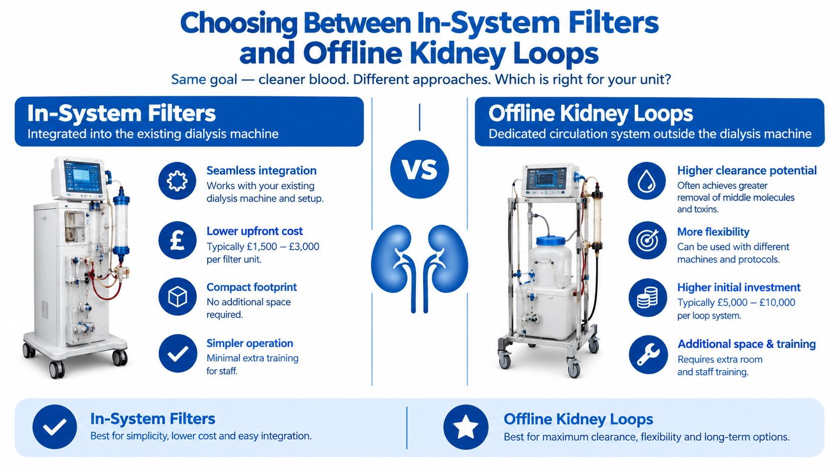
In-system filtration and offline kidney-loop filtration solve different problems. Treating them as interchangeable is a common reason commissioning work takes longer than expected.
Return-line filtration catches debris generated during operation before it returns to the tank. It is a sensible first line of defence for mobile plant and industrial circuits. Pressure-line filtration protects sensitive valves and actuators after the pump, but its housing and element must withstand the circuit pressure and required flow. A suction strainer protects the pump from larger debris, although excessive restriction can create pump starvation, so it shouldn't be used as a substitute for fine filtration.
An offline kidney loop takes oil from the reservoir, passes it through a dedicated high-efficiency filter and returns it independently of the main circuit. That makes it useful during initial filling, after a pump failure, following a cylinder rebuild or when debris may remain in pipework and manifolds. It can clean the reservoir without forcing the machine's operating flow through a fine element.
Choose the arrangement against the component sensitivity, viscosity, maximum flow and pressure conditions. Don't select an element solely because its nominal micron number looks impressive. Ask for the beta ratio, confirm bypass behaviour and validate the result through post-filtration particle counts.
| Situation | More suitable approach |
|---|---|
| Wear debris generated during normal operation | Return-line filtration |
| Sensitive downstream valves | Pressure-line filtration |
| Filling or topping up | Pre-filtered transfer equipment |
| Reservoir conditioning after repair | Offline kidney loop |
| Large installation requiring continuous conditioning | In-system filters plus offline filtration |
The kidney-loop filtration service is one example of the separate-circuit approach. It doesn't remove the need to control ingress at breathers, seals and transfer points, because filtration works best when contamination sources are controlled as well.
How to Take Accurate Hydraulic Oil Samples for Analysis
A sample is only useful if it represents the oil circulating through the system. Sampling downstream of a filter can make a dirty circuit look healthier than it is, while inconsistent sample points make trends difficult to trust.
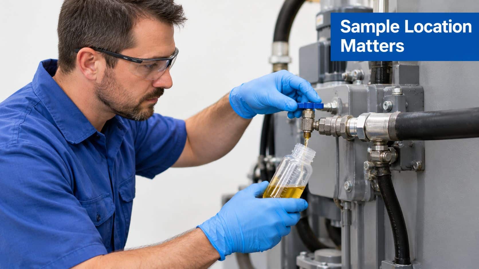
Use a fixed sampling point that isn't downstream of a filter. For a reservoir sample, operate the system for at least 15 minutes first, so the oil is mixed and suspended contamination can reach the sampling point (Offshore Energies UK environmental insight).
A practical sampling routine looks like this:
- Clean the sampling valve, surrounding fittings and bottle exterior.
- Confirm that the chosen point is consistent and upstream of filtration where appropriate.
- Run the machine for at least 15 minutes.
- Flush the sampling line sufficiently to remove stagnant oil and residue.
- Fill the laboratory bottle without touching its cap or opening.
- Record the machine, oil type, operating condition, sample point and filter status.
- Request particle count, water content and viscosity testing.
- Compare the result with the target ISO code and trend it against previous samples.
The sample point matters as much as the laboratory. A bottle taken from the bottom of a settled tank may show a different condition from oil moving through the circuit. A bottle taken immediately after a fine filter may hide the contamination that is damaging the pump upstream.
For organised condition monitoring, use an oil analysis service and keep the reports with filter-change records, repair notes and differential-pressure readings.
The following video can support technician training, but check the embedded frame at the page's responsive breakpoints so it renders at the intended aspect ratio:
Make the procedure accessible. UK Government guidance says non-decorative images need accompanying text descriptions, and important text in diagrams should also appear in normal page content (basic accessibility checks). Check every label, rating and symbol in maintenance visuals before publication. Where a video carries essential instructions, provide an equivalent transcript or written explanation, consistent with WCAG 2.2 Level AA guidance (UK public-sector accessibility guidance).
Common Pitfalls and Your Maintenance Schedule
A clean filter element does not prove that the hydraulic circuit is clean. A nominal micron rating can mislead if the element's beta ratio, flow capacity or bypass arrangement does not suit the circuit. Specify the beta ratio and confirm performance with post-filtration particle counts.
Check the blockage indicator during operation. Differential pressure rises as the element loads. If restriction becomes excessive, the bypass may open and send unfiltered oil around the element, or reduced flow may starve the pump. Calendar-based replacement alone can miss either condition.
Practical rule: Replace the element when condition data shows restriction or contamination, not simply because the maintenance date has arrived.
Find the source when particle counts keep rising. Common causes include a blocked breather, damaged reservoir seal, worn cylinder wiper, dirty filling equipment and debris left after hose replacement. Fit a new element only after correcting the route by which contamination enters, or the same failure will return.
Apply this routine:
- Before filling: Confirm the OEM ISO target, inspect the oil container and pass the oil through a suitable pre-filter.
- During transfer: Use dedicated, sealed transfer equipment. Keep hose ends capped and never place them on the floor.
- After filling: Circulate the oil, then take a representative sample from an agreed sampling point.
- During operation: Read filter indicators at normal operating conditions and investigate rising differential pressure.
- After repairs: Use offline kidney-loop cleaning if maintenance may have left debris in the reservoir or circuit.
- For every result: Record particle count, water content, viscosity, sample point and filter status.
- For every image or video: Check labels, captions, alternative text, transcript coverage and responsive frame sizing. Repeat important diagram text in surrounding HTML, following accessible content guidance.
MA Hydraulics Ltd supplies hydraulic filters and supports element cross-referencing, filter selection and filtration assemblies for mobile and industrial applications. Its team can match filter placement, pressure rating and transfer equipment to the required cleanliness target.
MA Hydraulics Ltd can also help configure transfer or kidney-loop filtration. Phone 01724 279508 or contact MA Hydraulics Ltd to discuss your oil cleanliness target and filtration setup.
