
You've found a compact hydraulic unit that fits the trailer, the voltage matches the battery, and the advertised pressure looks high enough. Then the practical questions start: will it lift at a useful speed, will the cables cope, and will the battery still start the engine afterwards?
A 12V hydraulic power pack can be a sensible way to operate mobile machinery without a mechanical pump drive. The right choice starts with the load and finishes with the electrical supply, not the other way round.
How a 12V Hydraulic Power Pack Works
Think of the pack as a small, self-contained hydraulic heart. The battery supplies stored electrical energy, the DC motor produces shaft rotation, and the pump draws oil from the reservoir and pushes it into the circuit.
The pump creates flow. Pressure develops when the cylinder's load resists that flow, which is why a pump can circulate oil freely but demand much more motor current when lifting.
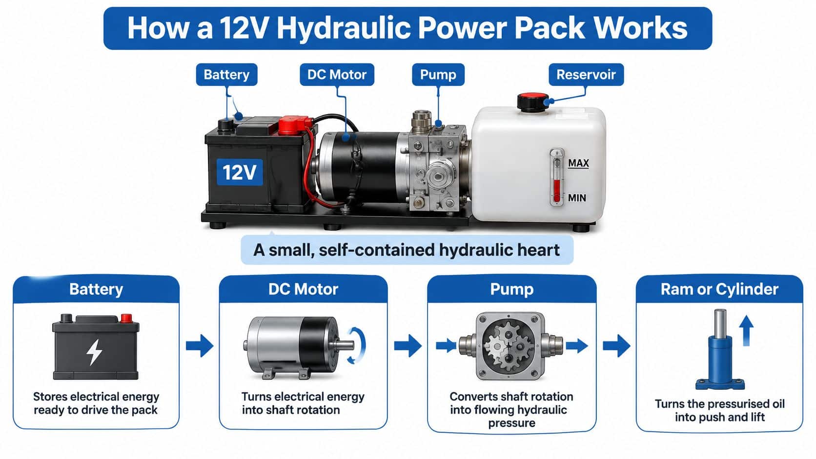
Following the energy path
Current reaches the motor through protected cabling and a suitably rated contactor. The motor turns the gear pump, which delivers oil into a manifold containing pressure-control and directional valves.
The relief valve opens a return path when pressure reaches its setting. It limits circuit pressure, but it doesn't make prolonged operation against a stalled cylinder acceptable: the motor still works hard and the oil heats up.
A directional valve sends oil towards the required actuator port. Its solenoid or manual control lets the operator command movement; a manual override must be used only according to the machine's operating procedure.
Core components of a 12V hydraulic power pack
| Component | Role in the circuit | What to check |
|---|---|---|
| 12V DC motor | Turns battery current into shaft rotation | Current draw at working pressure, in amperes |
| Gear pump | Draws fluid from the reservoir and creates flow | Flow in litres per minute at rated speed |
| Reservoir | Stores fluid, lets air separate and helps cooling | Capacity in litres and minimum fluid level |
| Relief valve | Limits maximum pressure in the circuit | Set pressure in bar and whether it opens freely |
| Directional valve | Routes flow to the cylinder or motor | Spool type, manual override and leakage |
| Filter | Removes contamination from the fluid | Micron rating and service interval |
| Battery and cabling | Supplies current to the motor | Voltage under load, cable size and fuse rating |
Why the reservoir matters
The reservoir must supply the oil displaced into the cylinder without uncovering the suction inlet. It also provides space for returning oil, allows entrained air to separate and helps release heat.
Check the level with the cylinder in the position specified by the manufacturer. Filling to the brim with the cylinder extended can cause overflow when it retracts.
A single-acting circuit powers movement in one direction and uses gravity or an external force for return. A double-acting circuit directs oil to either side of the piston, allowing powered movement both ways.
Tracing this path gives fault-finding a clear starting point: electrical supply, motor, pump, valves, then actuator.
Size a 12V Pack from Ratings and Battery Current
Key ratings on a 12V hydraulic power pack
| Specification | Unit | What it controls | Typical 12V range |
|---|---|---|---|
| Nominal voltage | V | Motor current and cable size | 12 V DC |
| Working pressure | bar | Available cylinder force | Illustrative selection band: 100–200 bar, limited by the relief setting |
| Flow rate | L/min | Cylinder speed | Illustrative selection band: 1–5 L/min |
| Reservoir capacity | L | Available fluid volume and cooling margin | Illustrative selection band: 2–20 L |
| Motor power | kW | Electrical demand and shaft output | Select from the supplier’s pressure-flow-current curve |
| Duty cycle | % on-time | Permitted running and cooling periods | Use the motor’s stated on-time, rest period and test conditions |
The bands above are illustrative screening values, not a specification for every pack. Maximum pressure and maximum flow on a product page may not be available simultaneously.
Battery efficiency also needs the right context. The government's grid-scale battery storage statistics concern electricity-system storage, not vehicle starting batteries, so their efficiency figures shouldn't be used to size a mobile hydraulic installation.
Work from the cylinder back to the battery
-
Define force and speed. Record required cylinder force in newtons and travel speed in millimetres per second. Use the actual linkage geometry, including the least favourable lifting position. Cylinder area determines the pressure needed for force and the flow needed for speed.
-
Calculate hydraulic power using pressure in bar × flow in litres per minute ÷ 600. This gives kilowatts at the hydraulic circuit, before motor and pump losses.
-
Allow for efficiency. Divide hydraulic power by the supplier's overall motor-and-pump efficiency, then multiply kilowatts by a thousand and divide by operating voltage to estimate amperes. Don't confuse motor shaft output with electrical input.
-
Separate starting, running and cycle-average current. Starting current affects contactors and protective devices; running current affects cables and voltage sag. Average demand helps assess battery depletion, but doesn't prove that the motor can survive a long uninterrupted run.
-
Set the permitted voltage drop. Obtain the motor's minimum acceptable terminal voltage under load. Include the positive and return cable lengths, terminals, isolator and contactor. Audio Jam Inc.’s explanation of wire gauge and voltage drop gives useful background, but select hydraulic motor cables in square millimetres using their actual installation conditions.
-
Coordinate the fuse and cable protection. The fuse must tolerate normal running and permitted starting current while protecting the cable. Check its time-current behaviour and DC breaking capacity, not just whether its label exceeds running amperes.
-
Check recharge capacity. Subtract other vehicle loads from the alternator's available output at the operating engine speed. Estimate ampere-hours used from current multiplied by running time in hours, then assess recharge time with charging losses and battery charge acceptance included.
A hypothetical worked sizing result
Suppose the cylinder calculation calls for 150 bar at 4 L/min, and assume 70% overall efficiency solely for this example:
- Hydraulic output: 150 × 4 ÷ 600 = 1 kW.
- Electrical input: 1 ÷ 0.70 = approximately 1.43 kW.
- Running current: 1,430 ÷ 12 = approximately 119 A.
- Alternative supply: At 24 V, the same assumed input requires approximately 60 A.
The sizing result is approximately 119 A while running, before starting demand and installation losses. That's the figure to test against the battery, cable route and required operating pattern, rather than choosing by pressure alone.
Practical rule: A battery's ampere-hour label doesn't guarantee that it can sustain the required current without excessive voltage sag.
Use the manufacturer's duty-cycle definition to translate your operating pattern into permitted running and cooling periods. If the electrical installation can't support the calculated duty, consider a different supply, additional battery capacity, an engine-driven arrangement or a purpose-designed pack.
Where 12V Power Packs Earn Their Place on UK Machinery
A farm trailer needs a tipping ram. The tractor has no spare power take-off, and there is no practical space for a belt-driven pump. A battery-fed 12V pack on the trailer can run its own hydraulic circuit and leave the tractor's mechanical drive alone.
That independence only holds if the battery can supply the running current for each tip, then recover. The battery works like a small header tank. The pressure rating tells you the cylinder can develop force. The tank decides how long the tap stays open before the level, and the voltage, falls away. Time spent travelling or being loaded is the refill window. Tip after tip with almost no pause is a different specification.
Match the function to its operating pattern
On a tipping trailer, the hard moment is often the start of the lift, while the body is still down and the load's weight works against you most. Check ram force at that point, then count how many tips fit inside one charging interval.
A tail-lift, or similar auxiliary lift, is busier. The heaviest loading hour sets both the current and the rest time. A suspended load still has to stay safe if the motor stops. For loader clamping, do not leave the pump running just to hold the jaws shut. A proper load-holding arrangement keeps the clamp closed with the motor off, so the battery is not spending amps on a static job. Steering assistance is stricter. How the machine behaves if assist is lost, and whether the controls stay sound, belongs in the design, not in an accessory list.
For loading-area projects, dock lift selection with Material Handling USA provides a useful application-level starting point. Establish platform travel, load arrangement and operating frequency before choosing the hydraulic supply.
New builds and retrofit requirements
England's farms spent £2.3 billion on machinery in 2023/24, and 74% purchased machinery during that period, according to Defra's Farm Business Survey machinery investment notice. These are England-specific figures, not a UK total, but they show agricultural equipment keeps being replaced and added to.
A new machine can be specified with controls, mounting and protection together. Retrofit work has to live with the hoses and cylinder already fitted, and with whatever charging current is left after starting and other loads.
A 12V pack fits poorly where the job needs high flow for long periods, or where auxiliary use would leave the engine hard to start. It earns its place when the function is intermittent, charging can put back the ampere-hours used, and no mechanical drive is available. Judge that pattern by sustained current and duty, not by the pressure figure on the data plate.
Choosing Between 12V, 24V and Engine-Driven Packs
Power source options compared
| Option | Best fit | Main limitation |
|---|---|---|
| 12V DC pack | Intermittent auxiliary functions on mobile machinery | Battery capacity and voltage drop under load |
| 24V DC pack | Higher power on a machine that already has 24 V | Needs a matching battery supply and components; the same power requires lower current |
| Engine-driven pack | Continuous or high-flow duty | Needs a usable power take-off or belt drive |
| Mains-electric pack | Fixed workshop or static installations | Needs a suitable mains supply at the site |
Choose for the machine, not the catalogue
Choose a 12V pack when the host machine has a suitable electrical system and the operating pattern suits the motor rating. Its advantage is straightforward integration, provided the battery and charging system have enough spare capability.
Choose a 24V pack when the machine already uses that supply or when a properly engineered supply change makes sense. Lower current can ease conductor and connection requirements, but it doesn't eliminate the need for correctly rated protection.
An engine-driven solution suits work where battery recovery periods would interrupt production. Compare the host machine's usable mechanical drive with a separate engine-and-pump arrangement, including mounting, guarding, maintenance access and exhaust management.
Consider the complete installation
For a self-contained engine option, a Honda hydraulic power-pack arrangement is a relevant configuration to assess. Engine power alone isn't the selection criterion: pump output, control valves, cooling and the required operating environment must also match.
A mains-electric pack is usually the more natural starting point for a fixed workshop machine. Confirm the available electrical supply and starting arrangements before finalising the motor.
Don't choose a small intermittent-duty pack and plan to compensate by ignoring its cooling requirements.
Installation cost includes more than the pack itself. Battery provision, charging equipment, cable routing, hydraulic plumbing and protective enclosures can change which option is practical.
Find the row that matches the machine's supply and operating pattern, then confirm the detailed component ratings. There isn't one best power source for every application.
Isolation and Safety Duties Under UK Machinery Rules
A raised ram can sit still on a flat 12 V battery and still crush someone. Voltage only shows whether the motor can turn. Oil trapped under a load, and gas in an accumulator, hold energy the battery is no longer supplying.
The Supply of Machinery (Safety) Regulations 2008 cover machinery supplied or placed on the market. PUWER 1998 covers work equipment once it is in use. Pressure-equipment rules generally concern equipment operating above 0.5 bar, as noted in the HSE machinery-safety review, so check classification and any exclusions in design rather than treating the whole machine as one category.
Low supply voltage does not remove fluid-injection, crushing or stored-energy hazards. A 12 V motor can still pull a large current for as long as the battery and its duty allow, and a stuck contactor or a failed valve can leave pressure on a circuit after the operator thinks the pack is off. Judge the electrical controls and the hydraulic circuit together.
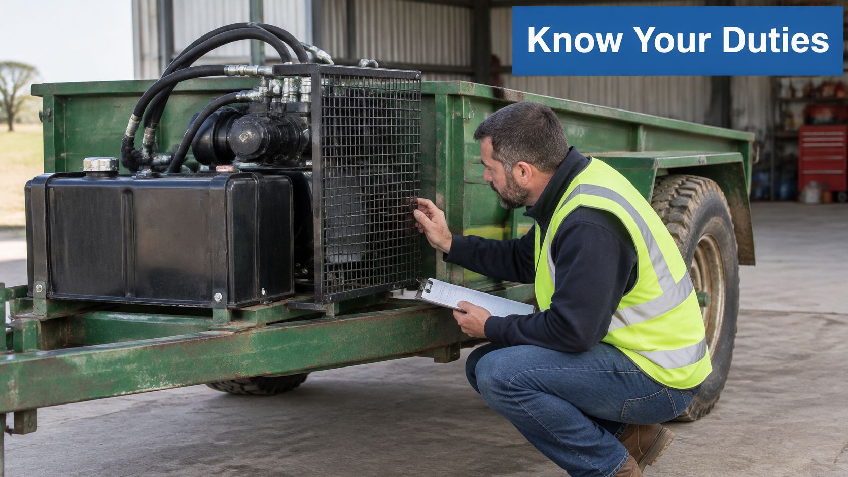
Isolate every source of hazardous energy
Isolation here works like making a charged store and a raised weight safe at the same time. The battery can restart the motor. The oil can still move the load. Begin with the machine-specific isolation procedure. Lower the load to a safe position or fit approved mechanical supports before depressurising. A closed valve is not a prop under raised equipment.
-
Isolate the electrical supply. Shut the equipment down and secure the battery isolator against reconnection. Where battery leads must be removed on a negative-earth installation, disconnect the negative lead first, following the machine manufacturer's procedure. On a 12 V pack the current can stay high while the voltage looks modest, so the isolator has to suit the current that battery can sustain and stay locked against a quick reconnection.
-
Release hydraulic pressure through the designated unloading or bleed arrangement. Do not loosen a hose fitting to bleed pressure, and do not assume the main relief valve will drain every trapped section.
-
Discharge accumulators safely. Follow the specified hydraulic discharge procedure and verify the result. Gas-side servicing requires appropriate competence and equipment.
-
Lock out operating controls and prevent remote or automatic starts. Verify isolation using the approved test method.
-
Check trapped-pressure locations. Load-holding valves can retain pressure downstream even when the main gauge reads zero. Confirm the relevant circuit sections are safe before opening them.
-
Inspect depressurised hoses for abrasion, damaged reinforcement and insecure fittings. Never search for a pressurised leak with a hand. Suspected injection injuries require urgent medical attention.
Commissioning needs a recorded check
HSE work-equipment guidance treats suitability, maintenance, inspection and training as central to safe machinery use. Turn those duties into a commissioning record, not a label on the tank.
- Electrical protection: Confirm cable routing, terminal covers, fuse coordination and isolator access. Match protection to the current and duty the battery can sustain, not only to the 12 V nameplate.
- Control behaviour: Test emergency stopping, power restoration and foreseeable control faults without exposing people to movement.
- Hydraulic integrity: Verify relief settings, hose ratings, controlled lowering and load-holding performance.
- Operator readiness: Record training, inspection responsibilities and the safe recovery procedure after a fault.
Document the checks and keep the circuit information with the machine. A compact 12 V pack belongs in that safety system. Specify its battery duty and isolator with the hydraulics, at the same time as the relief and load-holding valves.
Diagnosing Common Faults and How to Fix Them
Isolate, support loads and confirm the relevant circuit is depressurised before physical inspection. Energised measurements should be planned tests carried out by a competent person with guards and exclusion arrangements in place.
For slow movement, compare voltage at the battery with voltage at the motor during the same lift. A resting battery reading near 12.6 V, used here as an illustrative reading rather than an acceptance limit, doesn't establish that the supply will hold up under load.
Symptoms, likely causes and first fixes
| Symptom | Likely cause | First fix |
|---|---|---|
| Slow or weak movement under load | Low battery voltage or voltage drop in cables | Measure voltage under load; correct connections and shorten or upsize cable where calculated |
| Motor stops after repeated cycles | Duty cycle exceeded or cooling inadequate | Allow the specified rest time and reduce run time per cycle |
| Pump whine or foaming fluid | Air in the suction line or low fluid level | Restore the correct level, inspect suction joints and bleed using the prescribed procedure |
| Load drifts down | Internal leakage or failed load-holding valve | Secure the load, then test the valve and cylinder seals |
| No pressure at all | Blown fuse preventing motor operation, or relief valve stuck open | Check motor operation and fuse first; inspect the relief valve if the pump turns |
| Pump runs but cylinder does not move | Directional valve, coupling or connection fault | Check spool operation, pump drive coupling and hose routing |
Let the symptom guide the next test
A motor that stops after repeated cycles may have operated its thermal protection. Let it cool, then establish why the permitted operating pattern was exceeded; repeated resetting isn't a repair.
Whining and foaming warrant an inlet-side inspection. A suction joint can admit air without leaving an obvious external oil leak, so don't dismiss it because the floor is dry.
Escalate from simple checks to component testing
Use a controlled order: battery under load, fuse and connections, fluid level, suction joints, then valves and cylinder. The structured approach in hydraulic fault-finding techniques helps separate electrical faults from hydraulic leakage before parts are replaced.
Never increase a fuse rating to stop repeat failures, or adjust the relief valve just because a lift is slow. Find the overload, short circuit or pressure requirement first.
Correcting a loose connection may be straightforward. Valve testing, contamination removal and cylinder seal replacement need appropriate workshop facilities and should be planned accordingly.
Confirm Your Pack Specification Before You Order
Gather the required cylinder force and speed, working pressure, operating pattern, battery voltage and capacity, cable-run length and mounting dimensions. Add the cylinder bore, rod diameter and stroke, plus any existing circuit drawing or component identification.
A clear specification avoids selecting a pack that fits physically but can't complete the job. Procright's technical specification document explained is useful background for organising requirements, acceptance checks and interfaces in one document.
Turn requirements into an orderable assembly
At MA Hydraulics Ltd, we manufacture bespoke industrial power packs in house up to 11 kW and assemble Hydronit Mini Power Packs to suit customers' applications. A standard arrangement may suit the duty, while a bespoke assembly can address particular mounting, control or circuit requirements.
A bespoke build still needs a viable energy supply. It can't make an inadequate battery deliver unlimited power.
Before ordering, confirm:
- Performance: Voltage, pressure, flow and permitted duty.
- Installation: Cable cross-section, fuse coordination, mounting orientation and service access.
- Price scope: A current quotation in pounds sterling, stating whether VAT, delivery, installation and assembly are included.
For a specification review, have these details ready and email info@mahydraulics.co.uk. Include the busiest expected operating period, not just an average day.
We offer hydraulic component selection, technical advice and custom power-pack assembly to help match your 12V installation to its load and electrical supply. Visit MA Hydraulics Ltd, phone 01724 279508 today, or send us a message with your cylinder details, duty pattern and battery information.
