

A hydraulic return manifold is a safety-critical, contamination-sensitive assembly, not a passive low-pressure block. Hydraulic injection can occur at pressures as low as 7 bar (101.5 psi), so the manifold, its fittings and its maintenance procedure must be specified as pressure-containing parts.
The situation is familiar. A technician isolates a machine to change a return filter, loosens what appears to be a harmless connection and finds oil still trapped in the branch. Elsewhere, a cold start has raised backpressure through a restricted filter, or a damaged hose has sprayed fluid through a pinhole. The return circuit looked simple on the schematic, but the manifold has become the point where pressure, contamination, heat, vibration and maintenance risk meet.
For UK OEMs and MRO teams, that changes the specification process. Port count and purchase price matter, but they come after pressure rating, cleanliness, flow capacity, isolation, service access and environmental control. The right hydraulic return manifold protects the machine by managing what happens to oil after it leaves the actuator, not merely by providing a convenient collection point.
Why Hydraulic Return Manifolds Are Often Underestimated
A return manifold commonly sits in a visually unremarkable part of a machine. Several hoses enter a compact block, one line leaves for the filter or tank, and the assembly appears less demanding than a pump outlet manifold. That assumption can lead to poorly rated fittings, inaccessible drain points and a return filter selected for normal flow rather than the combined flow that can occur during simultaneous operation.
Return pressure can also rise unexpectedly. A blocked filter, collapsed hose, cold high-viscosity oil or failed check valve can restrict the common path. The resulting pressure may exceed the allowable return pressure of an actuator, motor case drain or seal arrangement, even when the circuit is described as low pressure.
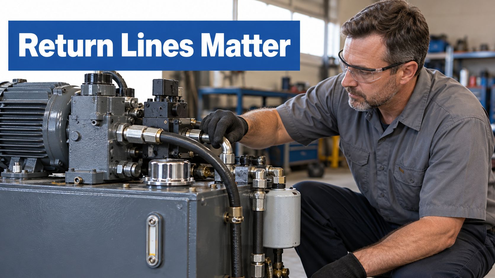
The injury risk is not theoretical
The UK Health and Safety Executive guidance on hydraulic injection injuries states that injuries have occurred at pressures above 100 bar, while evidence indicates injection can happen at pressures as low as 7 bar (101.5 psi). A pinhole release can penetrate skin and force fluid into tissue, potentially leading to major surgery or amputation.
Practical rule: Treat every return connection as capable of retaining stored energy until the circuit has been isolated, depressurised and verified at zero pressure.
That means a return manifold needs compatible hoses, correctly torqued fittings and protection against abrasion or impact, particularly on mobile machinery. Checking a suspected leak with a hand is unsafe. A visual inspection, card or other approved method should be used instead.
Start with risk, not price
A low-cost block that matches the port thread may still be unsuitable if its internal galleries restrict flow, its material is incompatible with the fluid, or its plugs cannot be removed safely. A sound procurement review asks whether the assembly has a documented pressure rating, a defined cleanliness condition, a sensible filter interface and an isolation strategy that a technician can use without reaching into a danger area.
The return manifold is therefore part of the machine's safety system. It deserves the same disciplined review applied to other pressure-containing components.
How a Hydraulic Return Manifold Works in Practice
The operating path is straightforward, but each stage affects the next:
- Actuator return flow: Oil leaving cylinders, motors, valves or auxiliary functions enters its assigned branch.
- Manifold collection: Internal galleries merge selected flows into a common outlet while keeping the external hose arrangement compact.
- Filtration: The combined stream passes through a return filter or another specified cleanliness-control device.
- Reservoir return: Filtered oil returns to the tank, where air separation, cooling and settling can take place before the next pump cycle.
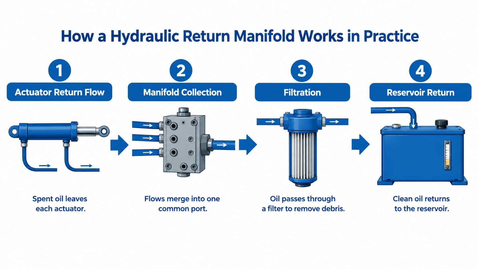
The manifold may be a simple parallel block with several inlet ports and one outlet. It may also include check valves, bypass arrangements, test points, drain ports or filter interfaces. The more functions integrated into the block, the more important the passage layout becomes. A short, generous gallery can reduce restriction, while an abrupt junction or undersized outlet can create local velocity, turbulence and backpressure.
Placement affects the whole circuit
Installers often position the manifold near the reservoir because this keeps the return route short and makes the filter and tank connection easier to service. That location also helps keep the common return line away from unnecessary heat and mechanical damage. However, proximity alone isn't enough. The route must avoid sharp bends, unsupported hose weight and points where vibration can load a fitting.
The relationship with the reservoir matters too. Poor routing can encourage aeration, while a submerged or badly positioned return can disturb the tank contents. The manifold should support a calm, controlled path into the filtration and reservoir arrangement instead of just terminating multiple hoses at the nearest available port.
Not every return should share one gallery
A common return can be appropriate for several actuator functions, but sensitive branches may need separate treatment. A motor case drain, for example, can have a very limited allowable backpressure compared with a general actuator return. Combining it without checking the manufacturer's limits can damage seals or affect motor life.
Use the schematic and component data to identify which flows may merge. Then verify maximum simultaneous flow, pressure loss, backflow risk and maintenance isolation. This is how a return block becomes an engineered flow-distribution component rather than a piece of low-pressure plumbing.
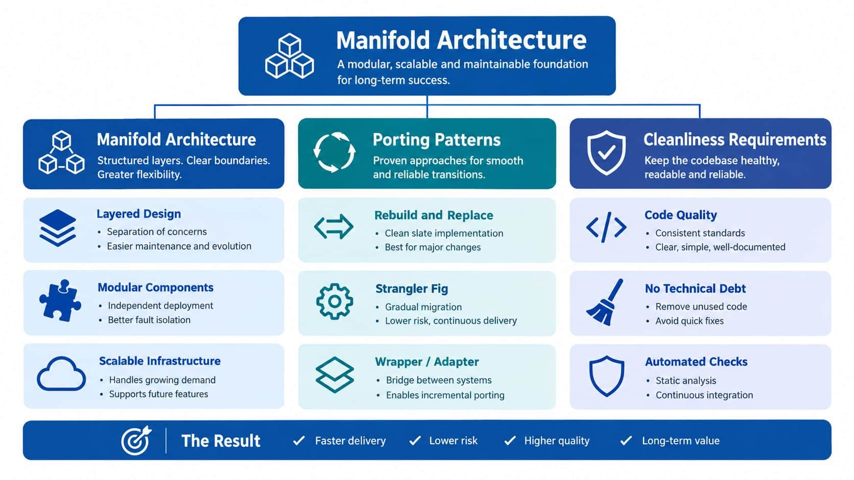
Manifold Architecture, Porting Patterns and Cleanliness Requirements
The internal geometry determines whether a manifold remains cleanable and predictable after manufacture, repair and commissioning. Drilled galleries, cross-bores, plugged passages and threaded ports can create pockets where machining debris or contaminated oil remains trapped. Those particles may later move into the reservoir, pump suction circuit or valve clearances.
A useful design review examines more than the external dimensions:
- Gallery arrangement: Keep the main route direct and avoid unnecessary changes in direction.
- Dead legs: Remove stagnant branches where reasonably practicable, especially on intermittent circuits.
- Plug locations: Make plugs accessible for inspection and replacement without dismantling unrelated equipment.
- Drain and sample points: Position them where trapped oil can be removed or tested.
- Port protection: Cap openings during storage, transport and assembly to prevent ingress.
The BS ISO 18413:2015 preview sets out inspection documentation and extraction and analysis principles for particulate contamination on wetted hydraulic-component surfaces and internal volumes. That is directly relevant to a manifold because its internal cleanliness can't be judged from an attractive external finish.
Flushing is not a substitute for clean manufacture
BS ISO 23309:2020 describes flushing as a way to remove residual or introduced particles from hydraulic lines and components, while also stating that flushing shouldn't normally be the sole cleaning method. The distinction matters. A manifold assembled with poor workshop controls may carry contamination into a flushing loop, and a design with stagnant pockets may retain it after the visible flow path appears clean.
Specify a cleanliness target, an inspection method and a commissioning record. Require capped ports, controlled assembly, suitable flushing verification and traceability for replaced plugs or fittings. For a returned or repaired block, ask what was cleaned, how it was inspected and which openings were protected afterwards.
Size filtration for the real return condition
A return filter should be sized for combined peak flow, not just the average flow of each branch. A low-flow agricultural function may operate intermittently, while a mobile attachment or several actuators can return oil at the same time. The manifold must pass that combined flow without creating unacceptable pressure loss or triggering an unsuitable bypass condition.
The hydraulic manifold design service from MA Hydraulics is one route for reviewing gallery layout, porting, return conditions and service requirements before manufacture. The same design discipline applies whether the block is standard, modified or fully bespoke.
How to Choose the Right Hydraulic Return Manifold
Selection should begin with the duty rather than the catalogue photograph. A compact mobile machine may need a lightweight block with protected ports and vibration-tolerant connections. A factory power pack may favour a larger modular assembly with accessible gauges, drain points and a filter arrangement that can be isolated without disturbing the rest of the plant.
Use the following comparison as a starting point, then confirm every value against the connected component manufacturers' data.
| Application condition | Suitable design emphasis | What can go wrong with the wrong choice |
|---|---|---|
| Compact mobile plant | Protected ports, low external plumbing, secure mounting and hose support | Vibration loosens fittings, abrasion damages hoses or access becomes impractical |
| Intermittent agricultural machinery | Drainability, capped connections, water-ingress control and easy seasonal inspection | Stagnant oil and trapped contamination remain in low-flow branches |
| Continuous industrial circulation | Stable pressure loss, filter access, sampling and heat management | Filter restriction creates backpressure across several connected circuits |
| Dirty or exposed environment | Guarded routing, contamination control and robust sealing | External dirt enters during servicing and accelerates component wear |
| Spill-sensitive site | Isolation, drain containment, drip management and controlled maintenance | A minor leak reaches floors, drains or nearby watercourses |
| Application requiring alternative fluid | Verified seal, hose, filter and coating compatibility | Incompatible materials swell, soften or lose sealing performance |
Pressure and compatibility come first
The manifold's pressure rating must suit the complete return circuit, including abnormal conditions. Check the maximum allowable return pressure for each connected motor, actuator, valve and filter. Also establish the expected temperature range, because oil viscosity changes affect pressure loss and filter behaviour.
Material compatibility includes more than the block itself. Seals, hose covers, filter media, coatings and thread sealants all need review before changing fluid. The HSE guidance on hydraulic fluids and machinery reinforces the need for suitable components, protective arrangements and safe maintenance rather than assuming a return circuit is harmless.
Factor in the site consequence
A leak inside a guarded factory cell presents a different containment problem from a leak on a machine working beside a drain or watercourse. UK safety documentation advises containing hydraulic-oil releases and preventing entry into sewers or public waters. Where a discharge reaches a watercourse, it should be reported to the Environment Agency or another appropriate regulatory body, as set out in the hydraulic-oil safety data information.
A good selection records the fluid, duty cycle, maximum flow, allowable backpressure, exposure, service access and spill consequence. Price then becomes one factor in a technically defensible choice.
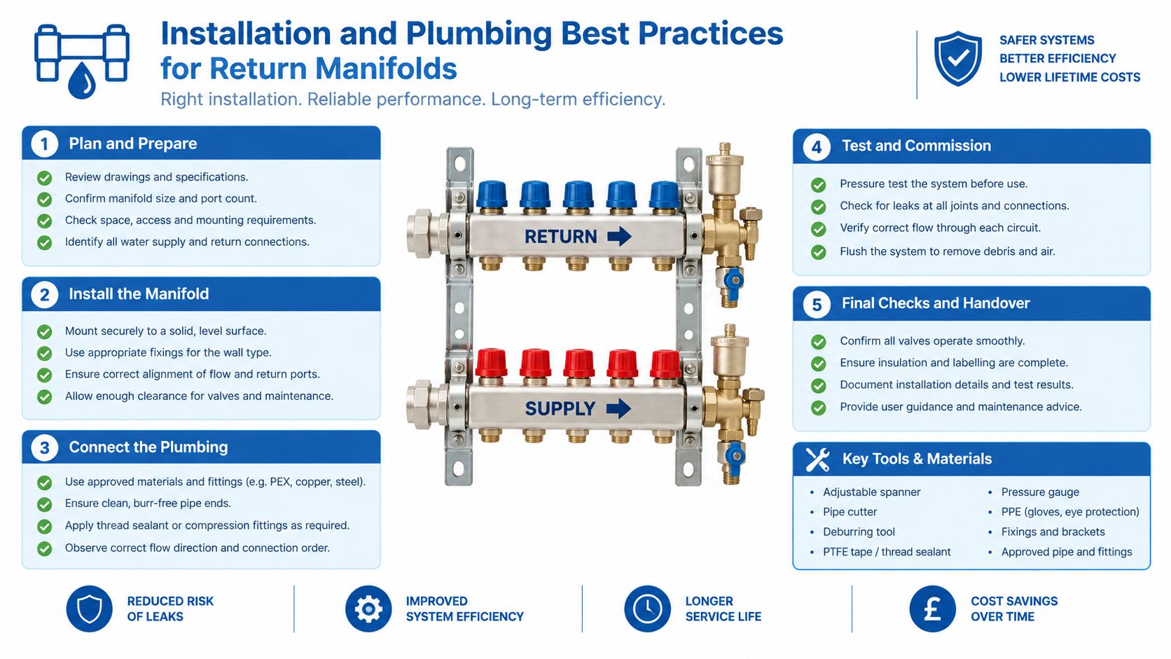
Installation and Plumbing Best Practices for Return Manifolds
A sound manifold can still fail if installers treat it as an ordinary plumbing block. Position it where technicians can reach the filter, drain and isolation points while the machine is safely supported. On mobile equipment, keep the assembly clear of moving linkages, hot surfaces, tyre debris and impact zones, then support hoses so their weight and vibration aren't carried by the manifold ports.
Use hoses and tubes that match the pressure, temperature, fluid and movement. Protect bends from abrasion and avoid forcing a hose into alignment with a fitting. A connection that is assembled under side load may seal initially but fatigue as the machine cycles.
Build the installation around isolation
Provide a clear method to isolate and drain each relevant section. Where appropriate, valves should be lockable or protected from accidental operation, and the technical file should identify the points used to confirm zero stored pressure. Include any filter bypass or differential-pressure indication in the commissioning and maintenance procedure.
Before removing a plug, hose or filter element:
- Park and secure the machine in accordance with the manufacturer's procedure.
- Support raised equipment with the specified locking device, stand or prop.
- Isolate the relevant energy sources and retain the key where the procedure requires it.
- Operate controls as directed to release stored pressure.
- Open the drain arrangement safely and verify zero pressure with the appropriate instrument.
- Check the work area for trapped oil and provide containment.
For vehicle and mobile plant work in Northern Ireland, HSENI's hydraulic-system safety alert specifically instructs workers to release stored pressure, never work on a pressurised system, support raised arms and avoid checking leaks with hands.
Commission cleanliness and flow
Clean every hose and connection before assembly, keep ports capped until connection and torque fittings according to the fitting manufacturer's requirements. Flush the system using a controlled method, then record the result rather than relying on oil that merely looks clear.
Confirm that the filter accepts the combined return flow, the bypass behaves as intended and no branch can reverse-flow into an inactive circuit. The MA Hydraulics installation guidance can support a repeatable approach to hose routing, component installation and commissioning.
Check the embedded video frame during publishing, because incorrect sizing can make an otherwise useful installation reference difficult to view.
Maintenance, Troubleshooting and Lifecycle Management
Maintenance starts with observing how the return circuit behaves, not with replacing parts on an arbitrary calendar. A rising filter indicator, warmer-than-usual return line, noisy pump, sluggish actuator or unexpected seal leakage can point to restriction, aeration, contamination or excessive backpressure.
Record symptoms alongside operating conditions. A filter that loads quickly after a pump replacement may be collecting introduced debris. A branch that remains dirty after a general flush may contain a dead leg or inaccessible pocket. A motor case drain that sees high pressure may be connected to a common gallery without adequate consideration of the motor's limit.
Use inspection evidence
A practical inspection routine includes:
- Filter condition: Record indicator status, element condition and any bypass event.
- Connections: Look for movement, abrasion, dampness or damaged protective sleeves.
- Manifold body: Check plugs, mounting points and evidence of impact or corrosion.
- Fluid condition: Review samples for particulate or water contamination rather than relying on colour alone.
- Access points: Confirm drains and test points remain usable after guards or attachments are fitted.
The MA Hydraulics oil-analysis service can be considered where fluid condition needs laboratory-supported evaluation. Sampling is most useful when the location, operating state and maintenance history are recorded consistently.
Repair the cause, not just the symptom
Replacing a filter may restore flow temporarily, but it won't correct a restricted gallery, a contaminated reservoir or a hose that is collapsing internally. Likewise, replacing a seal without checking return pressure can produce another failure.
When a machine is modified, review the manifold as part of the change. Add test access, separate a sensitive drain, improve isolation or replace a difficult-to-clean block when the existing architecture prevents safe maintenance. UK HSE states that hydraulic systems still require suitable equipment, understood operating limits, effective protective devices, competent maintenance and trained personnel, even where particular pressure-system regulations don't apply.
Real-World Applications Across Mobile and Industrial Systems
On mobile plant, the return manifold has to tolerate vibration, movement, dirt and imperfect service conditions. A compact block can reduce external hose runs, but it still needs a rigid mounting arrangement, protected ports and enough access for a technician wearing gloves. Agricultural machinery adds seasonal storage and intermittent operation, so drainability and protection from water ingress can matter as much as nominal flow capacity.
Materials-handling equipment often needs compact packaging around attachment circuits. A manifold may consolidate returns from clamps, rotators or auxiliary functions, but each branch must be checked for allowable backpressure and flow interaction. The operator's sightlines and the attachment's moving envelope also influence where the block and hoses can safely sit.
Factory power packs present a different balance. A larger modular or bespoke manifold may be easier to inspect, sample and isolate, especially where several actuators operate continuously. External access to filter elements, gauges and drain points can reduce maintenance exposure even if the assembly occupies more space.
Match the block to the service environment
A practical application review asks:
- Will the machine operate outdoors, indoors or near wash-down areas?
- Are returns continuous, intermittent or shared by simultaneous functions?
- Can a technician isolate and drain the block without entering a hazard zone?
- Could a leak reach a drain, hot surface, operator position or public area?
- Does the installation need a standard block, modified assembly or bespoke power-pack integration?
Layout affects safety beyond the hydraulic circuit. For broader workshop planning, RedAppy's guide to shop layouts offers useful context on arranging work areas, access and equipment movement so maintenance tasks don't create avoidable hazards.
MA Hydraulics Ltd supports component selection, manifold design and bespoke power solutions for mobile and industrial applications. Its work includes return routing, hydraulic components and power-pack assemblies, which can help teams resolve installations where a standard catalogue manifold doesn't provide the required access or circuit arrangement.
Common Misconceptions and Safer Design Choices
Misconception one: the return side is automatically safe because it isn't the pump outlet. It isn't. A blocked filter, cold oil or failed component can create unexpected pressure, and the HSE evidence on injection at 7 bar (101.5 psi) is enough reason to control every release point.
Misconception two: a larger filter solves contamination. It may improve capacity, but it won't remove particles trapped in dead legs, poorly cleaned galleries or stagnant branches. Clean manufacture, capped ports, controlled assembly, flushing verification and sampling access work together.
Misconception three: matching thread size proves compatibility. It doesn't confirm pressure rating, flow capacity, seal material, hose suitability, allowable backpressure or safe bypass behaviour. Dimensional fit is only the beginning of a technical review.
Misconception four: UK compliance is irrelevant to a return block. The Pressure Equipment (Safety) Regulations guidance explains that hydraulic oils are generally excluded from the definition of relevant fluids under the Pressure Systems Safety Regulations 2000, but that exclusion doesn't remove the duty to provide suitable equipment, understand safe working limits, maintain the complete system and train competent people. For assemblies placed on the Great Britain market, pressure equipment and assemblies with a maximum allowable pressure above 0.5 bar may require applicable conformity assessment and marking arrangements.
Specify the return manifold as part of the complete machine. Document its design pressure, test pressure, port ratings, cleanliness condition, isolation points and maintenance method, then have a competent hydraulic engineer review the result.
MA Hydraulics Ltd can help you select or develop a hydraulic return manifold with suitable return routing, filtration, component compatibility and service access for mobile or industrial equipment. Visit MA Hydraulics Ltd to discuss your application, phone 01724 279508 today, or send us a message.
