
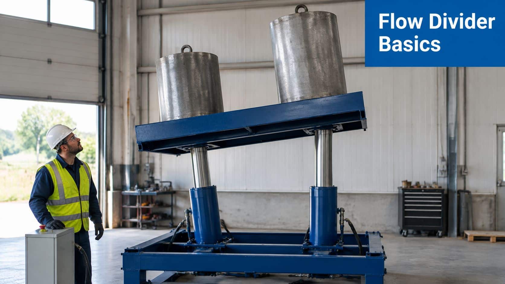
You're halfway through a lift and the platform isn't level. One cylinder has crept ahead, the load is skewing, and the operator is easing the lever off before a ram binds in its guide. Both cylinders share one pump, so the faster side isn't short of oil. It's taking more than its share because its load is lighter.
A hydraulic rotary flow divider is the part that should have kept those branches in step. What follows is for UK machinery and maintenance teams who need plain language on how that divider behaves in a real circuit, in metric figures, and an honest account of the jobs it cannot do.
What a Hydraulic Rotary Flow Divider Does and Why It Matters
A hydraulic rotary flow divider takes one inlet flow and splits it into two or more outlet flows in a set ratio. Gear sections sit on linked shafts. As the shaft turns, each section meters a fixed volume per revolution, so the branches share the supply without a separate directional valve on every line.
A kitchen tap feeding two hoses is a useful picture, with one difference. A plain tee sends more oil down the easier hose the moment one side meets less resistance. The shaft link between the gear sections holds the outlets nearer the set proportion even when one branch works harder, up to the point where leakage and pressure difference start to show.
Where the split earns its place
The British Fluid Power Association estimated the UK fluid-power market at approximately £1.1 billion in 2024, with hydraulics about 80% of that market, and it lists excavators, agricultural tractors and machinery, trucks, factory automation, renewable-energy equipment and infrastructure. Those are the machines where paired movement matters.
- Excavator and loader arms: two rams must extend together or the boom twists in its pins.
- Agricultural tractors and implements: a wide cultivator or a dual-motor drive has to track straight across a slope.
- Trucks and tipping gear: a body that rises on one side first dumps the load off-centre.
- Factory automation and renewable-energy equipment: paired actuators need a repeatable share of pump flow without a control cabinet on every function.
What it will not do
The divider doesn't protect a branch from excessive pressure. If a cylinder bottoms or a motor stalls, that outlet pressure climbs until a relief valve, a hose or a seal gives way. It also doesn't promise perfect synchronisation under every load. Cold oil, dirty fluid and a heavier actuator on one side all move the split away from the nameplate ratio.
Specify from the worst case: treat the divider as a precision metering and pressure-management part. Choose it from the hardest duty the machine will see, not from the nominal ratio printed on the body.
How the Gear Sections Split Flow Between Outlets
Oil doesn't "decide" which outlet to use. The gears decide, one revolution at a time. Three stages cover the path.
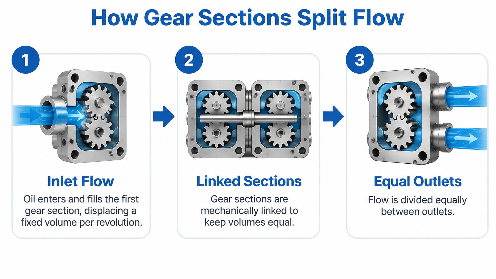
- Inlet fill. Oil enters the common inlet and fills the first gear section. That section displaces a fixed volume on every revolution, set by its width and tooth form.
- Linked sections. The sections share one shaft, so they turn at the same speed. Outlet flow stays in the ratio of the section displacements, not in the ratio of how easy each hose is to push oil through.
- Outlet delivery. Each port passes its share onward. On a two-section unit the two outlets together account for the inlet flow, minus the small internal leakage that never reaches either port.
Say a 1:1 divider receives 60 L/min. Each branch is nominally 30 L/min. A 60:40 unit on the same inlet gives 36 L/min and 24 L/min. Those figures are a starting point for sizing hoses and motors. They aren't a promise once the machine is working.
Why the real split drifts
The Health and Safety Executive guidance on fluid power is written for agricultural machinery, and the same physics applies on any UK hydraulic machine. Outlet synchronisation moves with pressure differential, oil viscosity, leakage, temperature, contamination and unequal actuator loads. A small measured imbalance is normal. The figure you're allowed to live with belongs on the datasheet, as a percentage of inlet flow, not as a guess on the workshop floor.
The shaft link limits how far the branches can separate, because one section can't race ahead of the other. It can't cancel leakage past worn side plates. During idle, intermittent or regenerative phases the ratio often stops holding altogether. Stored energy in a hose or a descending load can still creep one branch after its partner has stopped, even though the gears are no longer being driven by inlet flow.
Protection the divider cannot provide
A stalled actuator doesn't get a free pass. Each branch needs its own relief or pressure-limiting valve wherever a cylinder can bottom or a motor can lock. HSE guidance requires hydraulic machinery to include over-pressure protection, recommends hose-burst protection where a failure could injure someone, and states that protective devices must stay correctly adjusted. The divider itself is not that device.
On commissioning, record inlet flow, both outlet flows, pressure at each port and oil temperature under a balanced load and under a deliberately unbalanced load. That sheet is the baseline you'll use later when someone says the divider has "gone out".
A short walk-through of gear metering makes the three stages easier to picture. If you can't see the picture, use a text description of the same path: inlet fill, linked sections, then the two outlets.
A healthy unit keeps both outlets inside the stated tolerance across those balanced and unbalanced tests. The nominal ratio tells you the design split. It doesn't tell you the split you'll measure on a cold Monday with one ram heavier than the other.
Rotary Dividers Compared with Other Flow Dividers
Four common methods split flow. They aren't interchangeable, and picking the wrong one is why some circuits "synchronise" on the test bench and wander on the machine.
| Type | How it splits | Accuracy under load | Typical use | Main limitation |
|---|---|---|---|---|
| Rotary gear divider | Linked gear sections at a fixed displacement ratio | Good while clearances stay tight; falls as wear, dirt and pressure difference grow | Continuous sync of two motors or cylinders | Can’t correct a load that changes faster than leakage allows |
| Spool priority divider | Priority branch is fed first; surplus goes to the second outlet | Priority flow stays fairly steady; the second outlet takes what’s left | Steering or brakes ahead of a work function | Secondary function slows or stops when inlet flow is short |
| Orifice divider | Fixed restrictions share the inlet | Split moves with load and oil viscosity | Loose splitting where a few percent doesn’t matter | Poor choice for tight synchronisation |
| Electronic proportional sync | Valves trimmed from position or speed sensors | High, including through changing loads | Axes that must stay matched to a tight band | Cost, sensors, wiring and a controller to look after |
Rotary gear dividers win when the job is a fixed ratio, all day, with no control electronics. Two conveyor motors, a pair of lift cylinders, a dual-motor wheel drive. Accuracy is mechanical. Once side-plate wear, contamination or a large pressure difference opens extra leakage paths, the outlets drift and no trim pot will pull them back.
Spool-type priority dividers suit a different problem. Steering, trailer brakes or a safety function must be fed first, and the work circuit can wait. A priority flow divider valve is the right conversation when one outlet is allowed to starve. It is the wrong conversation when both outlets must stay in ratio.
Orifice dividers are cheap and compact. They suit a rough share of flow to two low-duty functions. The moment one branch sees more back-pressure, or the oil thickens overnight, the split moves. Don't use them to keep a platform level.
Electronic proportional sync holds position when loads swing quickly, because the valves keep correcting from feedback. You pay for sensors, drivers and someone who can fault-find the electrics as well as the oil. Move to that architecture when the loads change faster than a gear divider can correct, or when the allowed mismatch is tighter than any mechanical tolerance on the datasheet.
Selecting the Right Divider for Your Circuit
A divider can satisfy every line on its datasheet and still let two rams wander apart once it is bolted into a real circuit. The usual reason is a specification written around nominal conditions while the machine works at the extremes: a cold January start, a stalled actuator, a pump delivery that swings with engine speed. Write the spec around the worst case and the drift problem largely disappears before commissioning.
Datasheets and purchase orders in England, Scotland and Wales should lead with metric figures. UK government guidance on markings and sales requires metric measurements when goods are sold by quantity, and hydraulic equipment is not among the exceptions such as draught beer and cider by the pint, milk in returnable containers or precious metals by the troy ounce. Imperial figures may sit beside the metric line, but never more prominently.
| Parameter | Metric unit | Why it matters |
|---|---|---|
| Inlet flow range (minimum and maximum) | L/min | Sets the operating envelope the divider must cover |
| Displacement per outlet | cm³/rev | Fixes the nominal split ratio |
| Maximum operating pressure | bar | Must cover the highest pressure the circuit reaches |
| Permissible outlet imbalance | % of inlet flow | Defines acceptable drift in service |
| Oil viscosity range | mm²/s (cSt) at operating temperature | Affects internal leakage and outlet accuracy |
| Oil temperature range | °C | Changes viscosity and leakage across the duty cycle |
| Port size and thread | mm | Confirms hose and fitting compatibility |
Build the worst-case envelope
Work through the table as a specification, not a wish list. Start by converting actuator bore and required speed into flow, because cylinder area multiplied by piston speed gives the L/min each branch will demand. The arithmetic is set out step by step under flow rate calculations.
- Write the inlet as a range. A divider that is happy at one nominal flow can be noisy and inaccurate at the bottom of the pump curve, and can overspeed its gears at the top. Record minimum and maximum L/min for the intended duty, including warm-up and relief events.
- Fix displacement, then pressure. Displacement per outlet, in cm³/rev, sets the nominal ratio. Maximum pressure, in bar, must cover the highest pressure the circuit reaches, including the spike when an actuator stalls, not only the relief setting on the pump.
- State the imbalance you will accept. Write it as a percentage of inlet flow. If the platform can tolerate 3% and the datasheet offers 5%, the part is the wrong group size or the wrong construction, however attractive the price.
- Add oil and ports. Viscosity in mm²/s at operating temperature, and the oil temperature range in °C, decide how much internal leakage you will live with in January and in July. Port size in millimetres, plus the thread form, decides whether the existing hoses and fittings fit.
One more figure belongs on the order: the pressure each outlet will work against. A rotary divider splits flow; it does not equalise pressure, so two unequal loads still show up as a pressure difference across the outlets. Recording that difference alongside the ratio gives you a baseline for later, when drift appears and you need to know whether it came from wear inside the unit or from the circuit around it.
Check that every branch which can stall has its own relief or pressure-limiting valve, sized for that section's flow. Imperial conversions can sit in brackets for older machinery, but they should never replace the metric line the supplier will cut the part against.
Commissioning and Safe Maintenance of Divider Circuits
Hydraulic fluid injection is the hazard that sits under every flow check on a divider circuit. The HSE safety bulletin on hydraulic injection injury reports that injection injuries have occurred at pressures above 100 bar, while available evidence indicates injury can occur at pressures as low as 7 bar. A pinhole leak can be dangerous well below the pressure stamped on the component. Never find a leak by running a hand along a hose, and never crack a fitting to "see if it's live".

The service routine
HSE testing guidance is to begin below safe operating limits and raise pressure in stages, with a hold at each step, so a failed joint releases less energy. HSENI guidance requires stored pressure to be released before repair, with machinery or attachments in a safe, supported position. Apply that as six steps.
- Isolate the prime mover and prove it can't restart. A pressurised circuit can still move a load after the engine is switched off. Lock out the starter and the isolator, and keep the key with the person on the job.
- Secure the actuators. Lower any raised load onto stands or packers. A divider circuit often holds two rams, so both must be supported, not only the one you're about to open.
- Release trapped pressure on every branch. Crack each port only after the gauge on that branch reads zero. A divider can trap oil between its gears and a closed valve even when the pump gauge is already down.
- Inspect hoses and fittings cold. Look for chafing, a damp patch or a white crust of old seepage. If you suspect a pinhole, depressurise first. Gloves and eye protection stay on for the inspection, not only for the strip-down.
- Record the baseline once the circuit is back together. Inlet flow, both outlet flows, pressure at each port and oil temperature, first with the loads balanced, then with one branch deliberately heavier. Write the numbers on the machine file. A later argument about "how far out" needs those numbers.
- Retest from low pressure upward. Hold at each step long enough to see a weep or a creep before you add energy. Stop if a joint moves, a hose twitches or a gauge jumps.
If outlet mismatch, noise, heating or leakage shows up on that staged test, don't order a replacement divider yet. Filtration and oil condition come first. The next section is the order to chase the fault in.
Diagnosing Inaccurate Division or Circuit Faults
The usual phone call is simple. "It was fine at install, and now one side lags." A UCL study of a 22-tonne hydraulic excavator over 1,900 hours found that hydraulic reliability depends on pressure, flow, temperature, viscosity and particulate contamination, and that real-time metallic-particle monitoring can support condition-based maintenance. On UK mobile plant, agricultural kit and workshop repairs, dust, moisture and metal wear open clearances and unbalance motor loads. The divider is often reporting that, not causing it.
Isolate hydraulic energy before you sample or adjust anything. Sampling is part of the safety case, not a shortcut around it. Our notes on fault finding techniques sit alongside the checks below.
| Symptom | Likely cause | First check |
|---|---|---|
| Outlet imbalance grows over weeks | Contamination causing wear or clearance change | Oil particle count and filter condition against baseline |
| Imbalance only under heavy load | Branch back-pressure or a low relief setting | Pressure at each port under load |
| Divider runs hot and noisy | High viscosity or internal leakage | Oil temperature and viscosity at operating temperature |
| One motor slows steadily | Unequal motor load or inlet restriction | Motor current on each branch and inlet pressure drop |
| Imbalance returns after a filter change | Contamination source not cleared from the circuit | Particle trend over time and reservoir breather condition |
A decision order that starts with the oil
Work down this list. Stop at the first item that fails its acceptance check, fix that, and remeasure before you condemn the gears.
- Contamination and metal particles. Take a particle count from the reservoir and compare it with the commissioning sample. A count that has climbed, or a filter element heavy with bright metal, means the clearance is being cut away. Acceptance is "no worse than the baseline", not "the oil still looks amber".
- Inlet restriction. Measure pressure drop from the pump outlet to the divider inlet at working flow. A clogged strainer or a kinked suction-side hose on the pump side of the circuit starves both sections unevenly once aeration starts. Acceptance is a drop no higher than the figure you recorded at commissioning.
- Branch back-pressure. Gauge each outlet under actual load. If one relief is cracking early, that branch dumps oil and the other side appears to pull ahead. Acceptance is both outlets below their relief settings at the heaviest normal load.
- Load imbalance. Note which actuator is heavier, and whether the lag always sits on that side. A divider tracking the heavier branch is doing what leakage physics predicts.
- Viscosity. Measure oil temperature, then compare viscosity at that temperature with the range on the spec sheet. Oil far above the top of the range on a cold start, or far below it when the tank is overheating, moves the split on its own.
- Internal leakage, last. Only when the five checks above are inside limits, and the imbalance stays the same across load and temperature, does the evidence point at worn gear sections.
Replacing the divider is rarely the first response. Imbalance that follows branch load and oil temperature is the circuit talking. Imbalance that stays put after the oil is clean points at internal wear.
If the fault returns after a filter change, the source is still in the circuit. Check the breather, the rod seals that ingest dust, and any recent repair that left swarf in a hose. A new divider on dirty oil will tell the same story within weeks.
Confirm Your Divider Specification Before You Order
Send a short brief before anyone raises a purchase order. Build it from the worst-case envelope, the duty cycle (continuous sync, short parallel moves, or long idle between cycles), a circuit diagram and the commissioning baseline.
The brief should carry:
- Baseline readings for inlet flow, both outlets, port pressures and oil temperature, balanced and unbalanced.
- The fault in one line, if this is a replacement rather than a new machine, including how fast the imbalance grew.
- Port sizes in millimetres and the thread form, so fittings aren't guessed.
- A request that the supplier confirms outlet tolerance at your stated pressure and viscosity, the branch relief settings, and whether the group size suits the flow envelope.
We stock Vivoil hydraulic gear flow dividers in Group 0, Group 1, Group 2 and Group 3, including the Vivoil MIA-FD, and we can cross-check that brief against the circuit, match a replacement and advise on group size for the duty. Call 01724 279508 today, or send a message through our contact page and confirm the specification before you order.
MA Hydraulics Ltd supplies geared flow dividers, gear pumps and gear motors for mobile and industrial circuits, and we can match a divider to the flow, pressure and port sizes on your brief. If the platform is already drifting, bring the baseline readings and we'll help separate a worn unit from a circuit fault. Visit MA Hydraulics Ltd to start that check.
