
A hydraulic breakdown rarely announces itself cleanly. A telehandler starts lifting slowly, a power pack stalls halfway through a cycle, or the oil temperature climbs while everyone on site is still trying to decide whether it's a pump, a valve, or a load issue. The fastest teams don't guess. They work through fault finding techniques with a calm sequence, because the wrong swap can cost hours and still leave the fault in place.
In practice, good diagnosis is a mix of inspection, measurement, and reasoning. That lines up with the broader diagnostic framework used in engineering, where model-based, hardware-based, and history-based methods sit together rather than competing with one another, as described in the classic fault diagnosis review on diagnostic families and trend-based reasoning (review of fault diagnosis methods). It also matches the logic of evidence-based ranking, where the likely cause moves to the top before anything gets stripped down, which is the same principle behind statistical fault localisation in software troubleshooting (statistical fault localisation study).

For anyone managing plant, mobile machinery, or a workshop call-out rota, that matters because the fault isn't just a broken part. It's often a chain of symptoms spread across hydraulics, electrics, mechanics, and sometimes control logic. A useful upstream read on how maintenance priorities get organised across operations is how operations management works upstream, because the same discipline that keeps an operation flowing also keeps diagnosis from becoming random part-swapping.
When a Hydraulic System Fails on the Job
A loader comes in with weak lift. A press pauses mid-stroke. A dumper's auxiliary circuit chatters under load. In each case, the pressure is there to “just try a pump” or “throw a valve at it”, but the saving comes from stopping that reflex and ranking the evidence.
The formal diagnosis literature treats fault finding as a structured discipline, not a single test, and that's exactly how hydraulic work behaves on the shop floor. The useful split is simple. Model-based thinking asks what should be happening, hardware-based checking asks what is being measured, and history-based diagnosis asks whether the same symptom has been seen before in logs, returns, or operator reports (fault diagnosis review). That three-way view fits mobile and industrial hydraulics because the fault may live in the pump, the valve, the load path, or the control signal, and the symptom often arrives at the machine before it appears in a gauge.
Practical rule: if the symptom is vague, start by narrowing the fault family before you touch a spanner.
The best teams do that by separating the story of the fault from the machine itself. Was the loss of lift sudden or gradual. Did it happen hot or cold. Did the fault appear under load, during neutral hold, or only at one end of the stroke. Those answers don't fix the machine, but they stop you wasting time on parts that were never implicated.
On site, that means treating fault finding as a ranking exercise. The symptom points you toward likely causes, the measurements confirm or reject them, and the repair only happens once the evidence is solid. That mindset is what turns downtime into a controlled job instead of a drain on everyone's shift.
Safety Checks and Preparation Before You Touch Anything
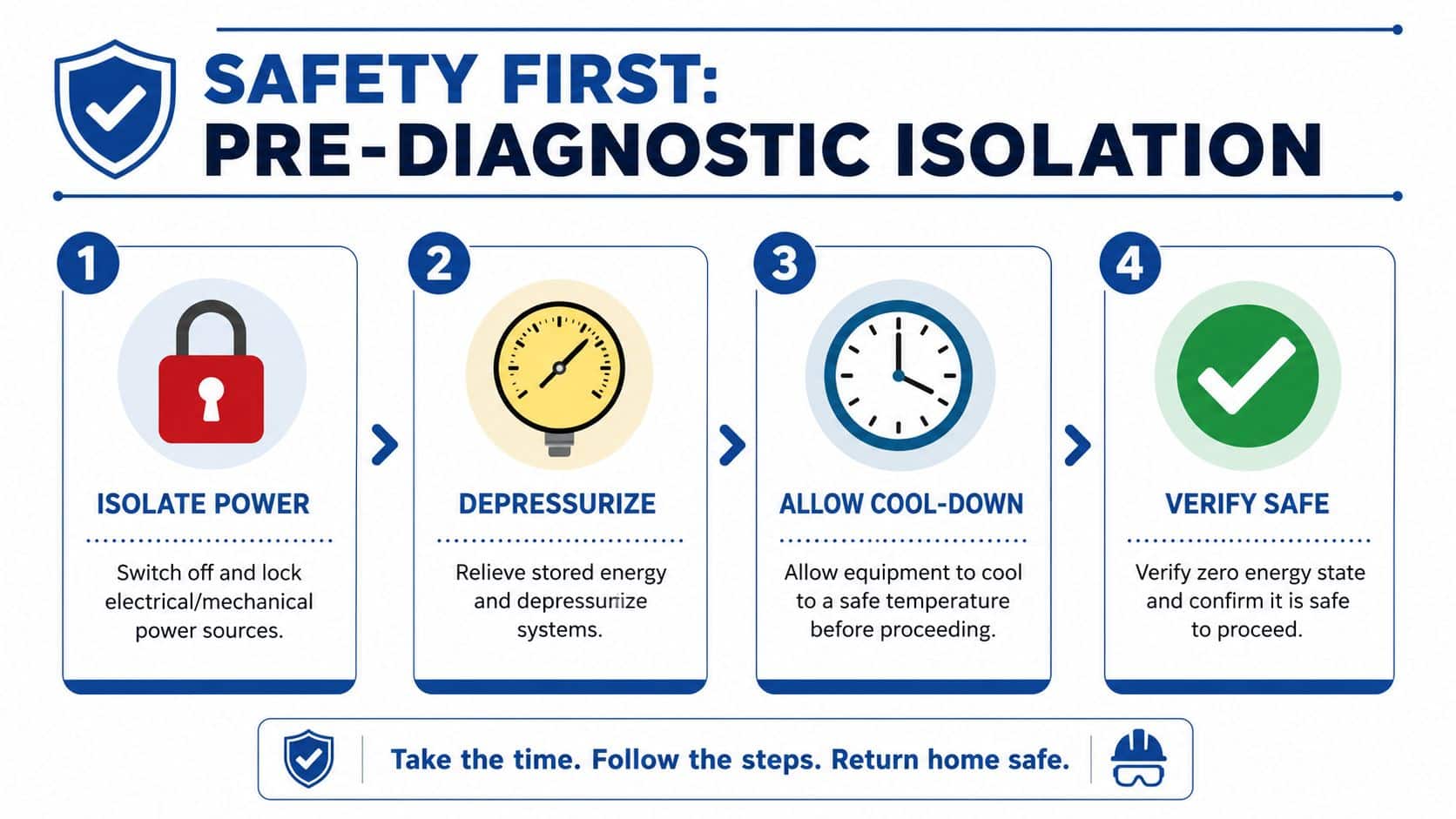
A hydraulic fault can look urgent, but the first job is to make the machine safe enough to inspect without adding a second failure. Isolate the power source, release pressure, and let components cool before you put your hands near hoses, manifolds, or fittings. Residual pressure can stay trapped in accumulators and closed circuits, and hot oil or hot steel will injure faster than most crews expect.
A proper walk-around often gives better clues than the first gauge reading. Look for fresh leaks, wet hose crimps, cracked sleeves, loose connectors, damaged bundles, low oil level, blocked breathers, and dirt drawn into the suction side. A machine that has been throwing oil onto the frame or running low on fluid does not need a clever theory first. It needs a careful inspection and a clear record of what is already visible.
The safest teams use a simple rule, STOP, LOOK, LISTEN and LEARN, before changing or moving anything (fault diagnosis techniques resource). That habit keeps you from building a diagnosis around one noisy component while missing the leak, the heat source, or the evidence already on the floor. I use the same discipline on hydraulic breakdowns that I ask electricians to use in electrical fault finding Brisbane, because safe isolation and evidence gathering work the same way across trades.
For hydraulic work, the prep list is straightforward:
- Lock out and tag out electrical and mechanical power sources before you approach the circuit.
- Depressurise completely, then prove the pressure is gone at the point you plan to test.
- Allow cool-down if the system has just finished a duty cycle or if the return line is hot.
- Wear PPE that fits the job, especially gloves, eye protection, and suitable spill control.
- Contain spills immediately, because a clean floor is part of the diagnostic picture, not just housekeeping.
Restraint matters just as much as preparation. Do not loosen fittings, crack lines, or back off adjusters until the root cause is identified. One small mistake at this stage can create a second fault, hide the original evidence, and make the repair harder to defend when the job is reviewed later.
Teams that want a stepwise way to approach faults can also use the MA Hydraulics troubleshooting methodology as a practical reference. The value is not in extra paperwork. It is in keeping the work controlled, so the diagnosis stays tied to the actual machine condition instead of guesswork.
The Three Diagnostic Families Every Engineer Should Know
A hydraulic machine that has already failed on site rarely gives you the whole story in one reading. The practical way to handle it is to sort every symptom into one of three diagnostic families, model-based, hardware-based, or history-based, then use them together to narrow the fault. That approach keeps the work grounded in how the circuit should behave, what the hardware is doing, and what the machine has done before (fault diagnosis review).
Model Based thinking
Model-based diagnosis starts with the expected behaviour of the circuit. If a cylinder should extend smoothly under a given load, pressure rise, flow demand, temperature, and response time should line up with that duty. When the machine does not match that pattern, the fault is real even before you have named the failed component.
That matters on hydraulic equipment because the symptom is often a gap between command and result. A valve can energise and still pass too little oil. A pump can turn normally and still fail to build pressure where the circuit needs it. The model gives you the first filter, so you are not chasing noise from a loose connection, a weak actuator, or a control issue that only shows up under load.
Hardware Based checking
Hardware-based diagnosis is the proof stage. Gauges, flow meters, temperature probes, multimeters, sample bottles, and visual indicators give you the readings that separate guesswork from evidence. The safe electrical fault find process is a useful reminder that controlled isolation and measured checks matter across trades, and the same discipline applies on hydraulics. The same practical order is reflected in the Practical Troubleshooting Methodology for Hydraulics, which fits field work because it starts from observable evidence rather than assumption.
A pressure reading by itself can still mislead you if you take it in the wrong place. Measure where the fault would have to show itself, then move through the circuit in a sensible sequence so the readings tell a story instead of giving you isolated numbers.
History Based diagnosis
History-based diagnosis is the memory layer. Previous failures, service notes, contamination history, and repeated operator complaints often point straight at the weak link. If a machine keeps blocking suction strainers, or the same valve bank fails again after hot-weather work, that pattern belongs in the diagnosis, not in the margin.
The workshop record saves time. The model indicates where the fault should be located. The hardware confirms whether it is present currently. The history reveals whether you are dealing with an isolated event or a recurring condition that will return unless the root cause is addressed. On mobile and industrial plant, that ranked view is typically faster than chasing the most dramatic symptom first, because the loudest fault is often not the initial fault.
Measurement and Test Procedures That Actually Work
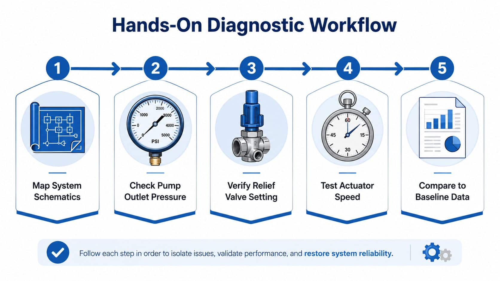
Start at the pump outlet, not at the vaguest symptom point. If the circuit is weak, noisy, or slow, measure pressure where the pump first proves itself, then step onward to the relief valve, directional valve, and actuator ports. A single pressure number at one point can mislead you, because a restriction, bypass, or control issue downstream may still leave one gauge looking acceptable.
A flow meter earns its place on the van because it separates “pressure available” from “flow available”. If the pump makes pressure but the actuator still crawls, you need to know whether the issue is flow starvation, internal leakage, or a valve that isn't opening properly. A timed cylinder fill can help when you don't have dedicated flow gear to hand, but it still has to be done against a known load and compared with a known-good machine or recorded baseline.
Temperature profiling matters too. Use an infrared thermometer for quick checks, or a contact probe when you need a steadier reading on pipework, housings, or tank walls. An overheated return line, valve block, or reservoir tells a different story from a warm motor casing, and those differences often decide whether you're chasing a relief issue, a bypass, or excessive internal leakage.
Tools worth keeping ready
- Pressure gauge set, with the right range and clean adapters.
- Flow meter, for proving output rather than assuming it.
- Sample bottles, because oil condition often explains recurring faults.
- Infrared thermometer or contact probe, for heat mapping.
- Multimeter, for supply, continuity, and signal checks.
A fluid sample is especially useful when the fault keeps returning after a basic repair. Contamination can point to worn components, poor filtration, or a breather issue, and it's easier to argue for deeper work when the oil tells the same story as the wear pattern. For teams needing a companion method for thermal checks, MA Hydraulics also has a thermal imaging inspection resource that fits the same measurement-first mindset.
The key point is sequencing. Test the pump, confirm the relief setting, check actuator response, then compare those readings with what the machine should do. That order avoids the common trap of finding a normal reading in one place and assuming the whole system is healthy.
Matching Symptoms to Likely Causes
A symptom-to-cause map saves time because it tells the engineer where to look first. It doesn't replace measurement, but it does stop you chasing the wrong end of the circuit while the actual fault sits elsewhere. The table below ranks likely causes in the order I'd check them on a live call-out.
| Symptom | Likely Cause Top Ranked | First Measurement |
|---|---|---|
| Slow actuator movement | Low pump output or internal leakage in the actuator circuit | Measure pressure at the pump outlet, then compare pressure at the actuator port |
| Erratic operation under load | Air ingress or a sticking directional valve | Check for foaming oil, then measure pressure stability during actuation |
| Excessive heat | Relief valve passing too much oil or a restriction causing bypass heating | Measure case or return-line temperature, then confirm relief pressure and flow |
| Foaming oil | Low oil level or suction-side air leak | Inspect reservoir level, suction hose joints, and breather condition |
| Noisy pump | Suction starvation or cavitation | Measure suction condition where possible, then inspect the strainer and hose routing |
| Cylinder drift | Internal leakage past the cylinder seals or valve leakage in neutral | Isolate the actuator and check pressure decay or movement under hold |
| Pressure spikes | Incorrect relief setting or a load-induced control issue | Measure pressure during the event at the point nearest the spike |
The order matters. Slow movement is not automatically a tired pump, and noise is not automatically a failed bearing. A cylinder that drifts under hold may be leaking internally, but it can also be held open by a valve fault, so the first test should always be the one that separates those two possibilities.
For a shop team, the smartest habit is to keep one eye on the symptom and one eye on the circuit path. If the fault appears only under load, chase load-dependent leakage, heat, or restriction. If it appears at neutral, look harder at holding valves, seals, and unwanted bypass.
Two Real-World Case Studies From the Workshop
A mobile agricultural loader came in with sluggish lift and a customer convinced the main pump had failed. The first check was pressure at the pump outlet, then at the lift spool and cylinder port. The pump produced usable pressure, but the flow dropped away under demand, and the suction strainer was heavily contaminated.
That changed the diagnosis quickly. The gear pump showed wear once the circuit was opened, but the strainer contamination told the bigger story. The fault wasn't just a tired component, it was a supply-side restriction that had been starving the pump and accelerating the damage. The repair made sense only because the evidence was collected in order, then confirmed against the symptom.
The first symptom is rarely the whole fault. It's the machine telling you where to look first.
The second job was an industrial power pack that overheated and kept tripping the relief circuit. The operator had already replaced a hose, which didn't help, and the oil had started to darken. Temperature profiling showed the valve block running much hotter than the rest of the system, and flow measurement pointed to a partially seized proportional valve.
The oil condition backed that up. The degraded fluid and the high local temperature were consistent with internal leakage and mechanical drag inside the valve assembly. Once the valve was repaired and the oil was corrected, the unit held pressure normally and the heat level settled back into line.
Both cases followed the same discipline. Gather the evidence, rank the likely causes, test the top candidate first, and prove the fix before handing the machine back. That's the practical version of the six-step workflow used in UK fault diagnosis guidance, and it works because it forces the repair to match the evidence rather than the other way round.
Quick Fixes, Escalation, and Getting Expert Support
Some faults do justify a quick fix. Topping up low oil, cleaning a blocked strainer, reseating a loose fitting, or correcting a clearly disturbed connection can restore a machine when the evidence points there. The key is that the quick fix must answer the fault, not merely silence the symptom.
Once the symptom keeps returning, or the readings point to internal wear, contamination, or a control issue you can't isolate cleanly, escalate. That may mean handing the job to a specialist, or passing the evidence to a supplier who can cross-reference the part, check the circuit type, and source the right replacement without guesswork. For support on that kind of handover, MA Hydraulics Ltd technical support is a sensible place to start, especially when the fault involves valve assemblies, power packs, or mixed-component systems.
When you do escalate, send the facts that matter:
- Machine type and duty cycle, so the supplier understands the load profile.
- Measured pressures and temperatures, taken at the points where the fault shows itself.
- Oil condition and contamination clues, especially if the fault is recurring.
- What's already been replaced or ruled out, so nobody repeats work.
MA Hydraulics Ltd supplies hydraulic components and bespoke power solutions for mobile and industrial applications, including gear pumps, valves, filters, gearboxes, couplings, manifolds, and assembled mini power packs, which makes it a practical option when diagnosis ends in replacement or rebuild. The win is not just getting a part, it's getting the right part matched to the fault evidence.
If you're facing a hydraulic fault that won't settle, speak to MA Hydraulics Ltd about component selection, cross-references, or a bespoke power pack build. Visit MA Hydraulics Ltd to get application advice, technical support, and a practical route from symptom to fix. Phone 01724 279508 today, or send us a message through the contact page if you need help turning a stubborn fault into a clear repair plan.
