
Your log splitter ram takes too long to reach the timber, but fitting a bigger pump risks overloading the motor when the split begins. The same problem appears on presses, clamps and agricultural machinery: you need speed while the actuator travels freely, then force when it meets resistance.
A two stage hydraulic pump can suit that pattern. The important question isn't just whether it moves the cylinder faster, though. It's whether it completes the required work with acceptable motor demand, temperature and energy per completed cycle.
How a Two Stage Hydraulic Pump Splits Flow and Pressure
Inside a typical two-speed or Hi-Lo pump sit two pumping elements on a common shaft: a large high-flow, low-pressure section and a smaller low-flow, high-pressure section. The pairing works like bicycle gears, where one ratio favours speed and another tackles resistance, except that the pump changes where the oil goes rather than any mechanical gearing.
Both elements turn whenever the shaft turns. The whole design therefore hinges on one question: where does each section's oil end up?

Follow the oil path
Both sections draw oil from the reservoir through their inlet connections. At low pressure, both deliver towards the common outlet, so their flows combine and the actuator travels quickly on the summed volume.
When pressure reaches the changeover pressure, the unloading valve diverts the large section's delivery back to the reservoir. That section keeps spinning, but because it now discharges at near-reservoir pressure it does almost no work, which is where the energy saving comes from. A check valve prevents working pressure feeding backwards into the unloaded section, and the small section alone supplies the actuator.
Simplified flow schematic
Reservoir → Inlet → High-flow stage → Unloading valve → Outlet → Actuator
Reservoir → Inlet → High-pressure stage → Check valve → Outlet → Actuator
After changeover: High-flow stage → Unloading valve → Reservoir
Text alternative: Both stages supply the actuator before changeover; afterwards, the high-flow stage returns oil to the reservoir while the high-pressure stage supplies the outlet. The labels identify each pumping and control function, so the sequence reads without relying on the visual.
Pressure and flow aren't interchangeable
For a hypothetical pump, hydraulic output power is:
Power in kW = pressure in bar × flow in L/min ÷ 600
Illustrative flow and hydraulic power by operating point
| Operating point | Flow delivered |
|---|---|
| 10 bar, approach | 60 L/min combined, giving 1.0 kW hydraulic output |
| 150 bar, loaded work | 15 L/min from the small section, giving 3.75 kW hydraulic output |
These aren't equal-power operating points. With the same installed motor, flow must fall as pressure rises to stay within its capacity; shaft input also includes losses.
That arithmetic also shows when the design earns its keep. The stage change pays only while the cycle includes a long, low-pressure travel phase. If changeover is set too low, the actuator slows earlier than it needs to and the loaded part of the cycle stretches, which raises energy per completed cycle instead of lowering it.
The trade-off is older than the hardware. Hydraulic presses date back to Joseph Bramah's 1795 patent, and they still answer to the same relationship between pressure and flow.
Keep three terms clear: changeover pressure triggers the transition, the unloading valve redirects delivery, and the high-flow stage provides rapid travel.
Two Stage, Single-Stage and Variable Pumps Side by Side
Two stage, single-stage and variable pumps compared
| Criterion | Two stage pump | Single-stage fixed pump | Variable displacement pump |
|---|---|---|---|
| Flow at low pressure | High, both sections combined | Fixed by displacement and shaft speed | Adjustable to demand |
| Flow at high pressure | Low, small section only | Approximately the same, allowing for leakage | Reduced to match demand within control limits |
| Control requirement | Unloading or sequence control with suitable routing | Relief protection and suitable directional control | Pressure compensator or load-sensing control |
| Heat at high pressure | Lower where unloading avoids surplus high-pressure flow | High where surplus flow is throttled or relieved | Low when correctly matched |
| Noise at high pressure | Check loaded and changeover noise specification | Check loaded noise specification | Check noise specification across control range |
| Relative purchase cost | Usually moderate, confirm quotation | Usually lowest, confirm quotation | Usually highest, confirm quotation |
| Commissioning effort | Moderate, changeover setting critical | Lower, but protection still needs checking | Higher, control tuning required |
| Best suited to | Fast approach then heavy work in a fixed cycle | Light or intermittent duty | Continuously varying demand |
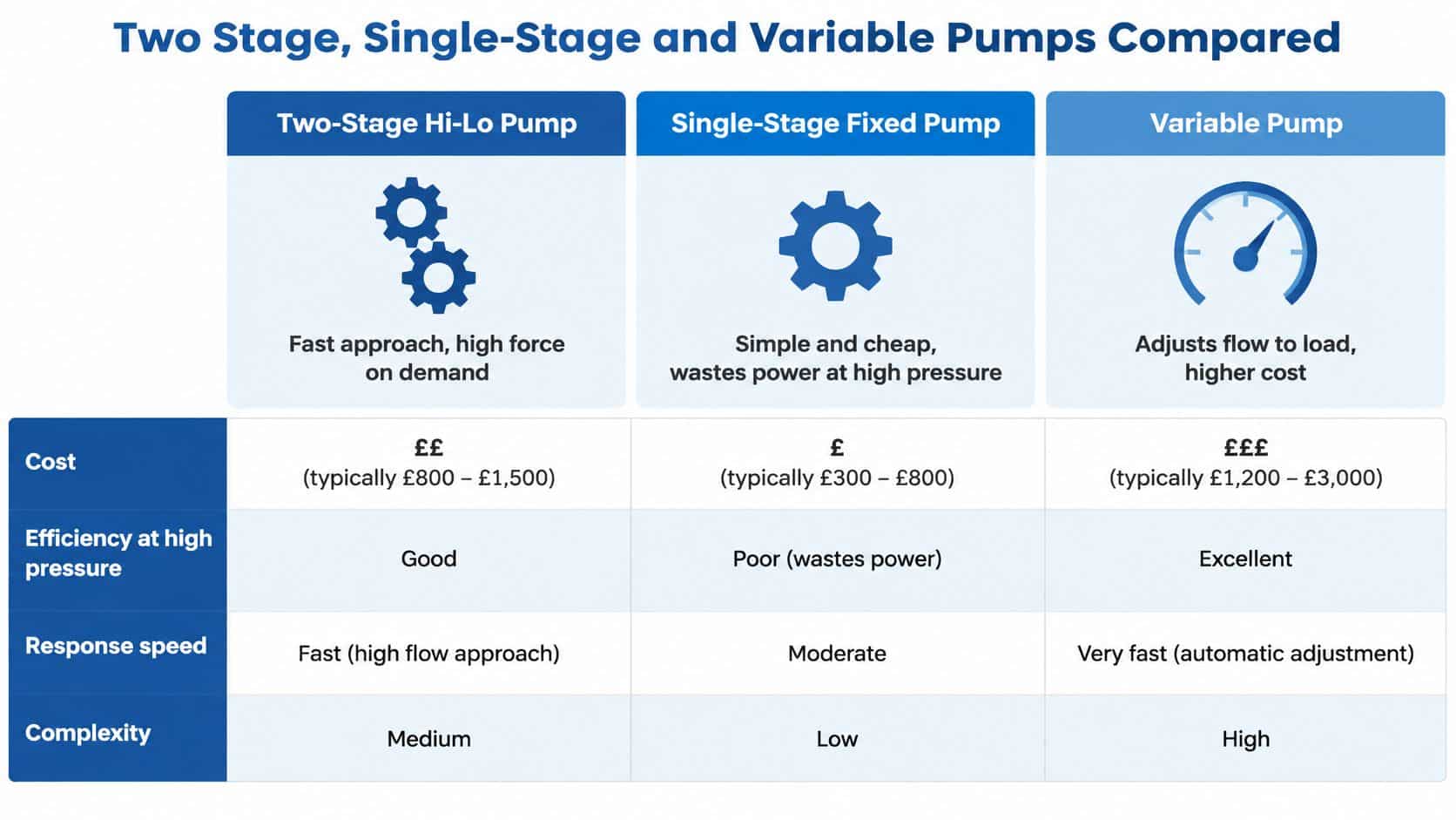
The graphic offers a quick comparison, but the qualifications in the table matter when specifying a circuit.
Read the circuit, not just the pump label
A single-stage fixed pump doesn't waste power merely because pressure is high. It wastes power when delivery exceeds useful demand and the circuit disposes of that surplus through throttling or a relief valve.
A two stage design reduces that mismatch for a predictable working cycle, but adds controls that must operate cleanly. A sequence valve isn't automatically a substitute for an unloading valve; its suitability depends on the complete circuit.
A variable displacement pump changes its delivery rather than relying solely on diverting a fixed delivery. Pressure compensation limits pressure, while load-sensing control responds to the pressure relationship across the metering circuit. Neither removes the need for correct valve sizing and commissioning.
Selection rule: Choose according to the machine's demand pattern, not a general ranking of pump efficiency.
For a visual accompaniment, use the embedded player below alongside the written explanation.
The player uses a proportional frame rather than a fixed height. Check its displayed proportions on mobile and desktop, and check technical terms in captions before relying on them, consistent with UK Government video publishing guidance.
Treat prices, noise and response as specification questions. Obtain current quotations and compare complete controlled assemblies, not a bare gear pump against a fully equipped variable unit.
Machines That Suit a Two Stage Pump
A machine designer should watch what happens between the start and end of a stroke. A long movement with little resistance, followed by a shorter demanding movement, is a promising duty pattern.
Recognise the working rhythm
On a log splitter, the wedge crosses an empty gap before touching the timber. Rapid advance saves waiting time; once splitting begins, controlled force matters more than travel speed.
In clamping and pressing, the tool closes towards the workpiece before applying the working load. The designer must control contact speed and pressure carefully, rather than letting a fast approach become an uncontrolled impact.
Front-end loaders and tipping gear need closer examination. An unloaded positioning movement followed by a loaded lift or tip may offer a useful distinction, but a loader raising a heavy load throughout its travel doesn't automatically suit Hi-Lo operation. The application name alone isn't enough to select the pump.
On mobile plant with limited power take-off or engine capacity, the constraint may be available shaft power rather than physical pump space. Check the actual lifting, positioning and return phases, including simultaneous actuator use, before assuming that reduced working flow is acceptable.
Recognise the poor fits
- Long high-pressure work: The large section contributes little useful output during most of the duty.
- Continuously changing loads: Some mobile drives need smooth adjustment across a broad demand range.
- A sufficient fixed flow: Extra changeover controls may add complexity without improving useful output.
Electrical symptoms also need separating from hydraulic suitability. DUCHENG Industrial's guidance on fixing overcurrent trips on multistage pumps is a related resource for drive-side investigation, but a multistage pumping application isn't the same as a Hi-Lo hydraulic circuit.
Watch the actuator, then record the load. Two distinct operating states are more informative than the machine's name.
Ask whether your machine repeats that distinct travel-and-work rhythm, and whether slowing the loaded movement still meets production requirements. If the operator constantly blends functions or changes speed under load, investigate a more adaptable control arrangement.
How to Size a Two Stage Pump From Measured Cycle Data
Begin with a representative operating cycle, including normal loads and warmed oil. Catalogue flow is only useful when you know the shaft speed, pressure and temperature at which you'll need it.
Build the duty specification
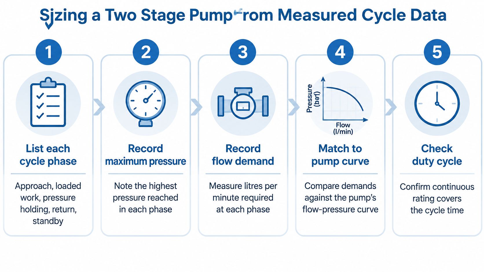
- Separate the phases. Record approach, loaded work, pressure holding, return and standby. Include dwell periods rather than timing only cylinder movement.
- Measure pressure. Use rated test points with a calibrated gauge or pressure logger. Record normal demand and peaks, distinguishing useful load pressure from line losses.
- Calculate actuator flow. Use Q = A × v, with consistent units. Required force determines pressure through force divided by effective piston area; required speed determines flow.
- Select combined approach delivery. The large section supplies the difference between the required approach flow and the small section's contribution. Don't size the large section alone for the entire combined requirement.
- Choose the transition. Place changeover above normal unloaded travel resistance, but below the pressure at which combined delivery would overload the drive. Allow for cold oil and load variation.
- Size loaded delivery. Select the small section's displacement for working speed at the intended shaft speed. Confirm its pressure rating covers maximum working demand, not merely changeover pressure.
- Check power and duty rating. Use P in kW = p in bar × Q in L/min ÷ (600 × efficiency), with efficiency expressed as a decimal. Check both operating modes and the transition.
The infographic summarises the measurement process; the detailed checks above distinguish cylinder force from pump delivery.
Work through cylinder volume
For a hypothetical 100 mm bore cylinder, piston area is approximately 78.5 cm². At an illustrative travel speed of 100 mm/s, equivalent to 600 cm/min, required approach delivery is approximately 47.1 L/min.
That calculation describes cylinder demand, not a pump's guaranteed output. Allow for actual volumetric performance at working pressure and check the manufacturer's delivery curve; our flow rate calculations guide explains the underlying relationships.
For a double-acting cylinder, calculate return demand using the annular area, piston area minus rod area. At the same target speed, the rod side needs less inlet flow, while oil leaving the full-bore chamber can impose a larger return-line flow.
Record a complete cycle before ordering. Also check shaft rotation, mounting, coupling, inlet capacity, fluid compatibility and continuous-duty limits.
Does a Two Stage Pump Actually Save Energy?
The ABB energy-efficiency and productivity plan reports that UK pumps consume approximately 20 TWh annually, associated with about 2.7 million tonnes of carbon emissions, while the broader pumping-system opportunity identified in UK efficiency legislation is roughly 20% to 30%. Those are system-level figures, not promised savings for a two stage installation.
The useful advantage is avoiding full approach delivery at working pressure. That can reduce required peak motor capacity compared with a fixed pump sized for the same rapid approach, but it doesn't prove lower electricity consumption over the complete job.
Where the advantage disappears
- Incorrect changeover: An early transition lengthens travel; a late transition increases drive loading.
- Continuous relief bypass: Electrical input becomes heat without completing useful movement.
- Throttled surplus delivery: Downstream valves discard flow the actuator doesn't need.
- Extended loaded operation: The duty offers little opportunity to benefit from rapid approach.
- Continuously varying demand: A correctly controlled variable or load-sensing pump may match the machine better.
Advantages can include fast positioning with lower peak drive demand, less high-pressure heat where surplus flow is avoided, and a lower purchase cost than variable control. Disadvantages include an unloading valve to commission, a critical transition setting, limited benefit during prolonged high-pressure work, and additional control-related noise and heat.
Prove the payback
Log pressure, actual flow, cycle duration, loaded and unloaded phases, standby time, oil temperature and motor electrical input over representative production. Compare alternative pumps doing the same work, at the same acceptable speed and output quality.
A faster cycle isn't automatically a lower-energy cycle. Measure electrical energy divided by successfully completed cycles.
Include standby consumption in that calculation. Hydraulic output power alone misses motor losses, unloaded pumping losses and auxiliary loads; our system efficiency guide helps frame the wider assessment.
Convert measured energy differences into annual electricity costs using your actual tariff and operating schedule. Compare that benefit with the installed cost, commissioning effort and maintenance implications, all priced in GBP. If the measured saving is negligible, specify the design for a demonstrated speed or packaging benefit instead of calling it an energy upgrade.
Diagnosing Faults Without Swapping the Pump
Split the machine cycle into unloaded approach, loaded work, pressure holding, return and standby. Measure actual flow, pressure and oil temperature in each phase, then compare them with the original duty and manufacturer's performance limits.
Slow extension, overheating and failure to reach pressure are symptoms, not component diagnoses. Hydraulics & Pneumatics' manufacturing downtime coverage reports that 68% of UK manufacturers experienced unplanned downtime in the preceding 12 months, reinforcing the value of structured investigation rather than repeated component replacement.
Start with safe measurements
Before installing instruments or opening connections, isolate and lock off the drive, secure raised loads, release stored pressure and discharge accumulators using the approved procedure. A stopped motor doesn't prove a hydraulic circuit is depressurised.
Use pressure-rated hoses, guarded test equipment and suitable test points. Never search for a pressurised leak with your hand, and don't adjust valves against an unsecured load.
Two stage pump symptoms, likely causes and first checks
| Symptom | Likely cause | First check |
|---|---|---|
| Slow approach, normal force | Unloading valve set too low, dropping the high-flow section early, or blocked inlet filter | Filter restriction, inlet vacuum and unloading valve setting |
| Fails to reach working pressure | Relief valve bypassing, or wear in the high-pressure section | Flow at working pressure and relief valve setpoint |
| Pressure drops under load | Internal leakage in the pump or cylinder seals | Controlled pressure-decay test with safely isolated circuit sections |
| Oil overheats during cycle | Continuous relief bypass or throttling of surplus flow | Oil temperature by phase and relief valve operation |
| Noise and cavitation | Restricted suction line, cold viscous oil or low oil level | Suction vacuum, oil level and oil temperature at start-up |
Distinguish supply, control and leakage faults
For slow approach with normal force, check the inlet and changeover behaviour before condemning the pumping elements. Excess inlet vacuum suggests restriction; an early pressure transition suggests that the high-flow section is unloading prematurely.
An unloading valve set too high can keep the large section connected beyond the intended operating range. Record the transition under controlled conditions and compare it with the approved setting, rather than adjusting until the machine sounds better.
For pressure loss, isolate circuit sections using an approved test arrangement. A pressure-decay test can reveal leakage in the isolated volume, but doesn't by itself prove pump wear. Cylinder seals, directional valves and other leakage paths must be separated from pump delivery tests.
Repair a restricted filter, incorrect valve setting or serviceable seal fault when inspection supports that diagnosis. Consider pump repair or replacement when measured delivery at rated pressure remains below the manufacturer's acceptable performance after inlet and control faults have been eliminated.
Compare readings at equivalent oil temperatures. Cold-start viscosity and seasonal conditions can otherwise make a healthy unit appear faulty; our fault-finding techniques guide supports a systematic investigation.
Confirm the Pump Size Before You Order
A nominal flow figure tells you what a pump can deliver, not whether it fits your machine. Prepare a duty sheet so whoever selects the pump can check both normal operation and the most demanding transition between stages, because that transition is where undersized drives and badly chosen sections reveal themselves.
Assemble the pre-order details
- Cycle record: Each operating phase, its pressure, duration and required movement.
- Flow requirements: Combined approach delivery and small-section working delivery.
- Changeover setting: The intended transition, with allowance for travel resistance and drive capacity.
- Motor assessment: Available shaft power, speed and efficiency allowances.
- Cylinder geometry: Bore, rod diameter, stroke and the effective areas used.
- Operating conditions: Oil grade, temperature range, filtration and inlet arrangement.
- Control arrangement: Unloading, relief, directional and load-holding functions.
- Mechanical interfaces: Mounting, shaft, rotation and port connections.
Choose a two stage pump when measured duty shows distinct operating phases and testing supports a worthwhile energy or speed benefit. Judge the options on energy per completed cycle rather than catalogue flow: a two stage arrangement saves energy only when the machine spends time in both phases, and a cycle that rarely unloads the large section gives you extra controls without the saving. Variable delivery suits demand that changes continually, while a single-stage arrangement remains the sensible choice when light or intermittent duty doesn't justify additional controls.
Match the component to the complete installation
Our team can help check cycle data, cross-reference components and advise on pump selection and power-unit specification. Confirm current stock and the available product range directly with us before committing to a design.
MA Hydraulics offers the Vivoil HI-LO Double Pump, a high-low pressure pump, and stocks Vivoil Hydraulic Unidirectional and Reversible Gear Pumps in Group 0, Group 1, Group 2 and Group 3; we also manufacture bespoke industrial power packs in house up to 11 kW.
A suitable replacement must match the circuit as well as the mounting. Send the existing component identification together with measured duty requirements, particularly if you're changing cylinder speed, working pressure or the prime mover.
At MA Hydraulics Ltd, we offer hydraulic component selection support and bespoke power-unit solutions to help match a two stage pump to your machine's duty. Contact our team by phone or email today, or send us your cycle data and duty requirements before committing to an order.
