
You've got a motor speed, a gearbox drawing and a machine that needs more torque at a lower speed. The tooth counts look straightforward, but the catalogue torque figure doesn't quite match your calculation. Before choosing a replacement, you need to know whether the difference comes from efficiency, rounding or a ratio entered the wrong way round.
Double reduction gearbox calculations become easier to trust when every speed and torque result also passes a power check. A gearbox can exchange speed for torque, but it can't create power. That gives you a practical test for the sums before you commit to a shaft arrangement, coupling or purchase order.
Core Formulas for Ratio, Speed and Torque
A double reduction gearbox has two gear stages in series, so calculate each stage separately before combining their effects. For a conventional compound train, the first driven gear and the second driving pinion share an intermediate shaft.
Use dimensionless ratios, speed in rpm, torque in N·m, power in kW and dimensions in millimetres. Keep efficiency as a decimal in calculations, rather than entering a percentage directly.
Formulas for double reduction gearbox calculations
| Quantity | Formula | Units |
|---|---|---|
| Stage ratio | Driven gear teeth ÷ driver teeth | Dimensionless |
| Overall reduction ratio | Stage 1 ratio × stage 2 ratio | Dimensionless |
| Output speed | Input speed ÷ overall ratio | rpm |
| Ideal output torque | Input torque × overall ratio | N·m |
| Actual output torque | Ideal output torque × stage 1 efficiency × stage 2 efficiency | N·m |
| Input power | Input torque × (2π × input rpm ÷ 60) ÷ 1000 | kW |
The power formula converts rotational speed into angular speed in rad/s before multiplying it by torque. The final division converts watts into kilowatts. Keep that conversion visible on your worksheet rather than hiding it inside a calculator shortcut.
Separate geometry from losses
The tooth counts establish the speed relationship. Efficiency establishes how much of the input power reaches the output shaft, so it belongs in the torque calculation, not as an extra reduction in output speed.
For an illustrative helical-stage estimate, you might test efficiencies between 0.96 and 0.98 per stage. Those are assumptions for a preliminary calculation, not guaranteed performance figures. Use the manufacturer's efficiency information for the actual gearbox, operating speed, lubrication and load.
If you need to identify the driver, driven gear and intermediate shaft first, the explanation of how gearboxes work provides the mechanical context.
Bench rule: Write the ratio convention at the top of the worksheet. For reduction calculations, use driven teeth divided by driving teeth throughout.
Keep formulas as selectable text, not just labels inside a drawing. The UK Government's basic accessibility guidance supports normal text that readers can resize or customise.
For UK procurement, convert imperial specifications into metric units. If a manufacturer quotes in US dollars, show a dated GBP equivalent and state whether VAT, delivery and installation are included. Start the engineering calculation with the overall ratio, because every subsequent shaft result depends on it.
Working Out the Overall Reduction Ratio
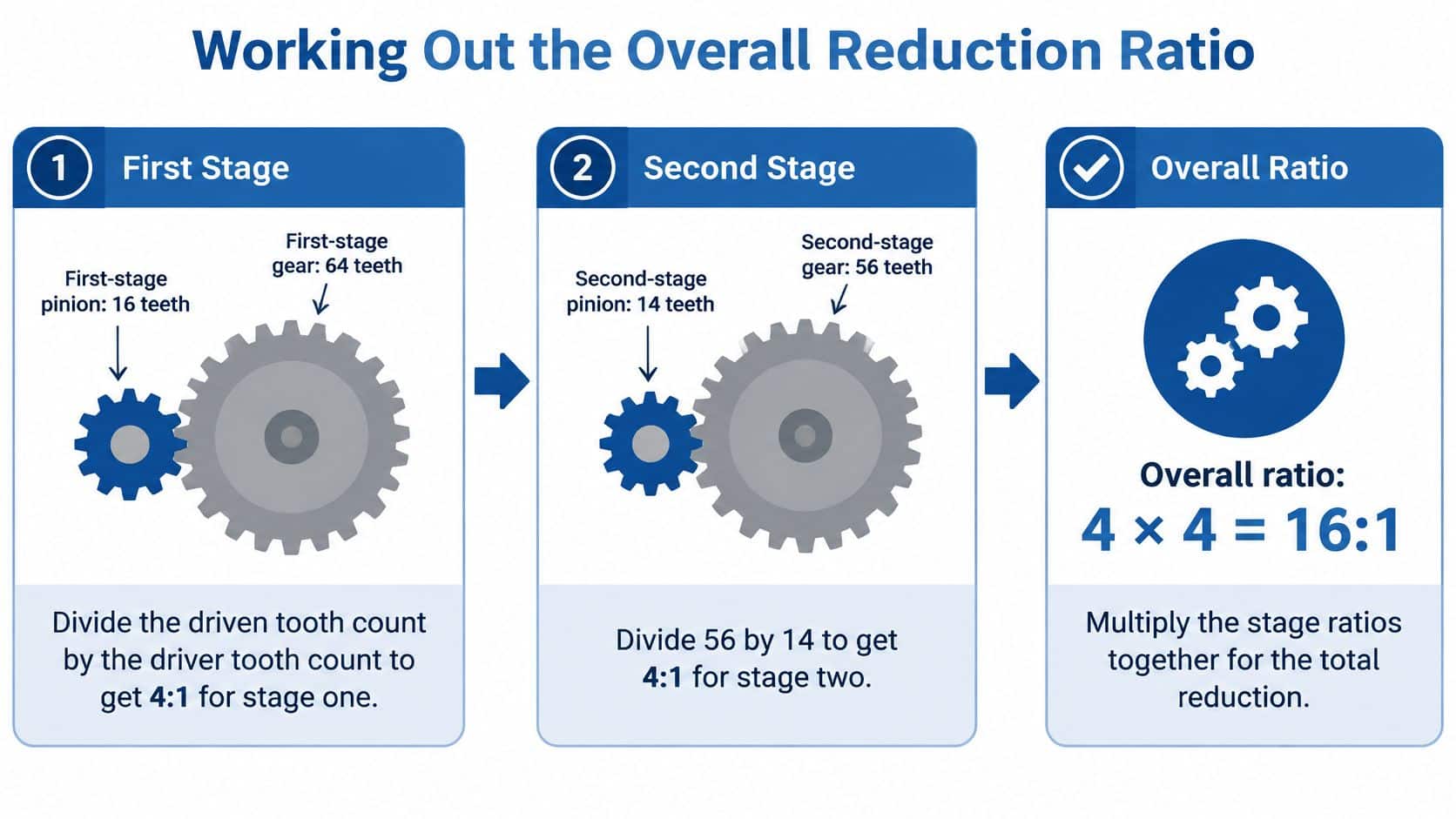
Say the gearbox drawing shows a 16-tooth pinion driving a 64-tooth gear, followed by a 14-tooth pinion driving a 56-tooth gear. Treat this as a hypothetical compound gearbox, with the first driven gear fixed to the same shaft as the second pinion.
The layout below illustrates that calculation.
Follow the power path
-
Confirm the mating gears. Read the tooth counts from the manufacturer's drawing or count the actual teeth where inspection is safe. Don't substitute a catalogue family designation or assume that gears beside one another on a parts list mesh together.
-
Divide the first driven gear by its driving pinion: 64 ÷ 16 = 4.0. The intermediate shaft therefore runs at the input speed divided by this stage ratio.
-
Calculate the second mesh independently. Here, 56 ÷ 14 = 4.0. Check that this pinion is on the intermediate shaft, rather than treating both pinions as though they receive motor speed directly.
-
Multiply the stage ratios: 4.0 × 4.0 = 16.0. The output shaft turns once for every sixteen input turns.
-
Compare the result with the exact specification. A nameplate stating 16:1 agrees with this hypothetical train. A stated ratio of 15.6:1 would require investigation into the tooth counts, gear pairing, drawing revision or whether the catalogue value is nominal.
The ratios multiply because the second stage receives a speed that the first stage has already reduced. Adding them would describe neither shaft's actual motion. You can prove the multiplication without torque figures by following any chosen input speed through both successive divisions.
Keep exact divisions in the worksheet
Store each ratio as its original tooth-count division wherever possible. A calculator or spreadsheet can carry the full result into the overall ratio, leaving rounding until the final displayed answer.
For this example, the divisions happen to give whole-number ratios. That isn't a requirement: a valid gear pair can produce a fractional ratio, and a non-terminating decimal isn't evidence of an incorrect tooth count. The warning sign is a stage ratio that doesn't agree with the exact driven-to-driver division.
Display final calculated results to two decimal places where useful, but don't confuse display precision with measurement accuracy. A tachometer reading, a nominal motor speed and an exact tooth-count ratio have different levels of certainty.
For choosing a ratio from a required machine speed, the reduction gearbox ratio guide helps connect the mechanical calculation to the application. Also record shaft direction separately: a reduction-ratio magnitude alone doesn't specify which way the output rotates.
Calculating Output Speed and Torque Step by Step
Use a hypothetical operating point of 1450 rpm input speed and 40 N·m input torque, with a 4.0 ratio and 0.96 efficiency at each stage. These are calculation inputs, not a rating claim for a particular gearbox.
Follow speed first, then torque
The intermediate speed is 1450 ÷ 4.0 = 362.5 rpm. The final speed is 362.5 ÷ 4.0 = 90.625 rpm, displayed as 90.63 rpm, or 90.6 rpm when using a single decimal place.
Ignoring losses temporarily, ideal output torque is 40 × 16.0 = 640 N·m. Combined efficiency is 0.96 × 0.96 = 0.9216, giving actual output torque of 640 × 0.9216 = 589.824 N·m, normally displayed here as 589.8 N·m.
You can check that torque stage by stage. The intermediate shaft carries 40 × 4.0 × 0.96 = 153.6 N·m, and the output carries 153.6 × 4.0 × 0.96 = 589.824 N·m.
Worked example at 1450 rpm and 40 N·m input
| Quantity | Stage 1 | Stage 2 | Overall |
|---|---|---|---|
| Input conditions | 1450 rpm; 40 N·m | 362.5 rpm; 153.6 N·m | 1450 rpm; 40 N·m |
| Ratio | 4.0 | 4.0 | 16.0 |
| Efficiency | 0.96 | 0.96 | 0.9216 |
| Output speed (rpm) | 362.50 | 90.63 | 90.63 |
| Output torque (N·m) | 153.60 | 589.82 | 589.82 |
| Output power (kW) | 5.83 | 5.60 | 5.60 |
The stage power values come from torque multiplied by angular speed at the corresponding shaft. The final 5.6 kW output is therefore a calculation result, not an additional assumption.
Why efficiency doesn't change the speed ratio
In a positively engaged gear train, the teeth constrain the relative shaft speeds. Friction consumes power, so less torque is available at that constrained speed than the loss-free calculation predicts.
That statement assumes the stated input speed is maintained. If the motor slows under load, output speed also falls because its input has changed, not because gearbox efficiency should be multiplied into the speed formula.
Keep intermediate shaft results on the worksheet. If the final answer is wrong, they show which stage introduced the error.
Proofread any gear-train diagram for input speed, intermediate speed, output speed, torque, efficiency and units. Check decimal points and multiplication signs, and retain the same figures in selectable text or a table. The Government Communication Service accessibility standards require appropriate alternative text for informative images and identify significant information presented only as images of text as an accessibility problem.
Maintenance planning is a separate check from the arithmetic. For broader servicing context, you can compare duty-cycle transmission maintenance schedules using SAAT Repairs Corp's transmission-service explanation, while retaining the gearbox manufacturer's lubricant and inspection requirements as the controlling instructions.
Checking Power Balance and Efficiency
A plausible torque figure isn't enough. At a steady operating point, output shaft power must equal input shaft power minus losses. Use this as a pass-or-fail check before accepting the calculated performance.
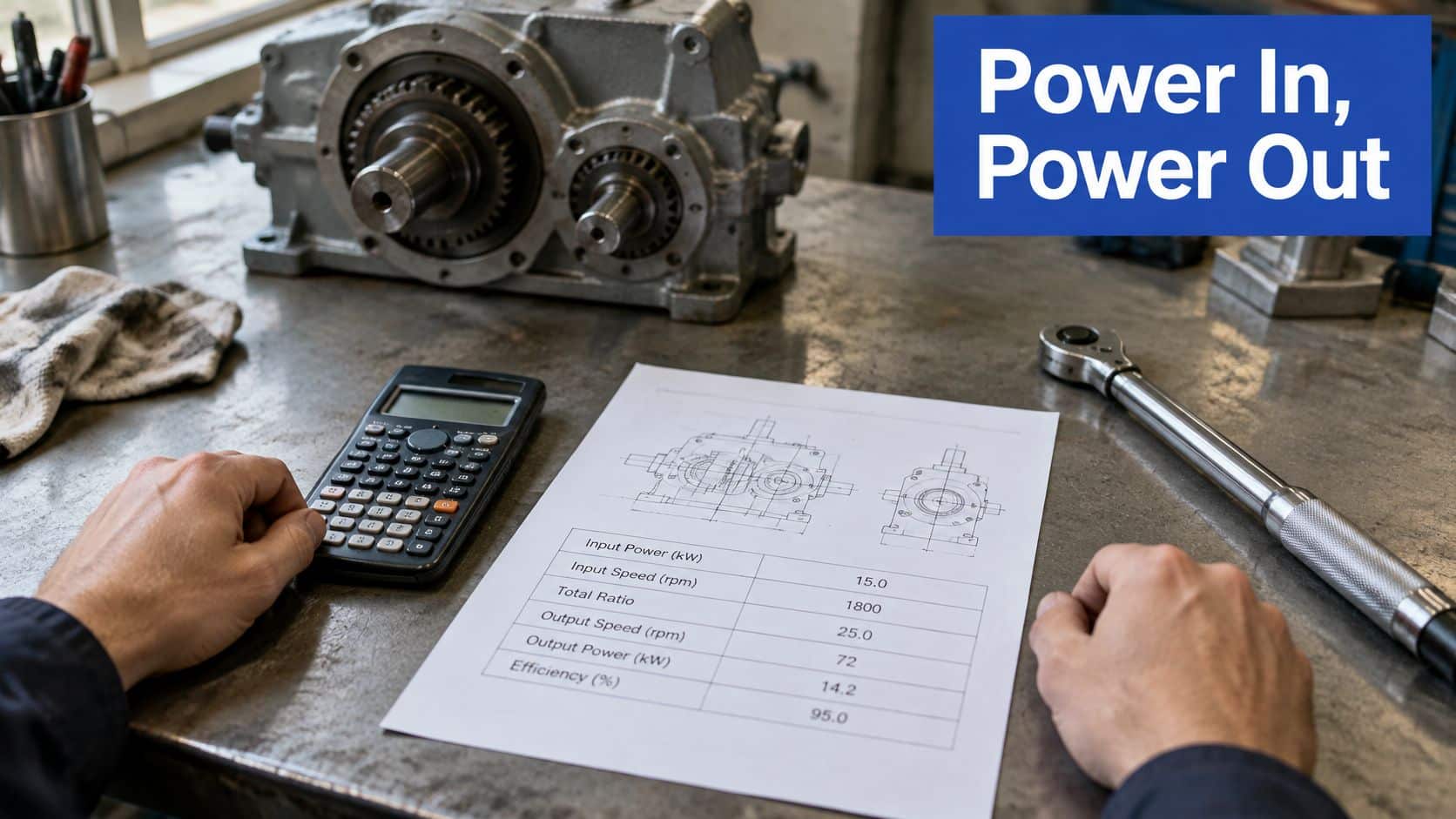
A worksheet that keeps torque, speed and units together makes this check easier to audit.
Test the shaft powers
| Test | Calculation using the hypothetical operating point | Result |
|---|---|---|
| Input angular speed | 2π × 1450 ÷ 60 | Approximately 151.8 rad/s |
| Input power | 40 × (2π × 1450 ÷ 60) ÷ 1000 | Approximately 6.07 kW |
| Output angular speed | 2π × 90.625 ÷ 60 | Approximately 9.49 rad/s |
| Output power | 589.824 × (2π × 90.625 ÷ 60) ÷ 1000 | Approximately 5.60 kW |
| Power ratio | Unrounded output power ÷ unrounded input power | 0.9216 |
Using the shortened display figures gives 5.6 ÷ 6.07 ≈ 0.92, which agrees with the assumed combined efficiency within rounding. Use unrounded values for the actual acceptance check.
If output power exceeds input power, reject the worksheet result. Check the ratio convention, torque units and angular-speed conversion before investigating anything more complicated.
If output power is lower than expected, establish what the efficiency assumption includes. Bearing drag, seal friction and oil churning may already be included in a manufacturer's overall efficiency figure, so subtracting them again would double-count losses.
Test capacity separately
Power balance proves physical consistency, not gearbox strength. Compare the calculated 589.8 N·m with both continuous and peak torque ratings, then assess starting, reversing and shock loads.
For an illustrative preliminary sizing exercise, service factors of 1.25 to 1.5 would produce torque selection targets of approximately 737.3 to 884.7 N·m. Don't treat that illustrative range as a universal rule: use the manufacturer's application method and check thermal capacity independently.
Acceptance check: A calculation can conserve power and still specify a gearbox that cannot withstand the duty.
Two conversion errors deserve an immediate check. Omitting 2π makes calculated power about six times too small; treating rpm directly as rad/s makes it about nine and a half times too large. Neither error can be repaired by changing the assumed efficiency.
Common Mistakes and How to Fix Them
Inverting the stage ratio is an easy way to turn a reducer into an apparent speed increaser on paper. It reverses the intended speed and torque relationship, even when every later calculator entry is internally consistent.
Keep a small sketch beside the worksheet with arrows marking the driver and driven gear. That is more useful than relying on the words small gear and large gear, particularly when checking an unfamiliar assembly.
Common calculation mistakes and their effect
| Mistake | Effect on the result | Correct approach |
|---|---|---|
| Stage ratio as pinion ÷ gear | Speed and torque relationships reversed | Divide driven gear teeth by driver teeth |
| Adding stage ratios instead of multiplying | The example becomes 8.0 rather than 16.0, giving twice the correct output speed | Multiply the stage ratios |
| Rounding a stage ratio early | Output speed drifts from the true value | Keep unrounded ratios until the final answer |
| Ignoring combined efficiency | About 8 per cent of ideal torque is incorrectly retained as usable output | Multiply ideal torque by both stage efficiencies |
| Omitting 2π in the power formula | Power about six times too small | Use angular speed in rad/s, calculated as 2π × rpm ÷ 60 |
| Using rpm directly as rad/s | Power about nine and a half times too large | Convert rpm with 2π ÷ 60 |
Distinguish rounding from an incorrect assumption
Suppose a stage ratio is 3.97, but someone enters 4.0 for convenience. That changes the calculation input, rather than merely shortening the displayed answer, and shifts every downstream speed result.
Be equally careful with percentage language. In the worked example, losses are 7.84 per cent of ideal torque. Saying the ideal figure overstates the actual available torque uses a different denominator, giving approximately 8.51 per cent. Writing the two torque figures beside the percentage removes that ambiguity.
Finish each worksheet with these habits:
- Label every value. Put units beside torque, speed and power.
- Preserve precision. Keep exact tooth divisions in spreadsheet cells.
- Check identification. Match the calculated ratio to the correct nameplate and drawing.
- Audit power. Recheck the balance whenever an input or efficiency assumption changes.
Don't adjust efficiency merely to make a preferred catalogue size appear suitable. Resolve the mechanical or application mismatch before ordering.
Confirm Your Gearbox Specification Before You Order
Use the calculation as an input to selection, not as the complete specification. A buyer needs the operating duty and mounting details alongside the calculated shaft performance.
Run the order checklist
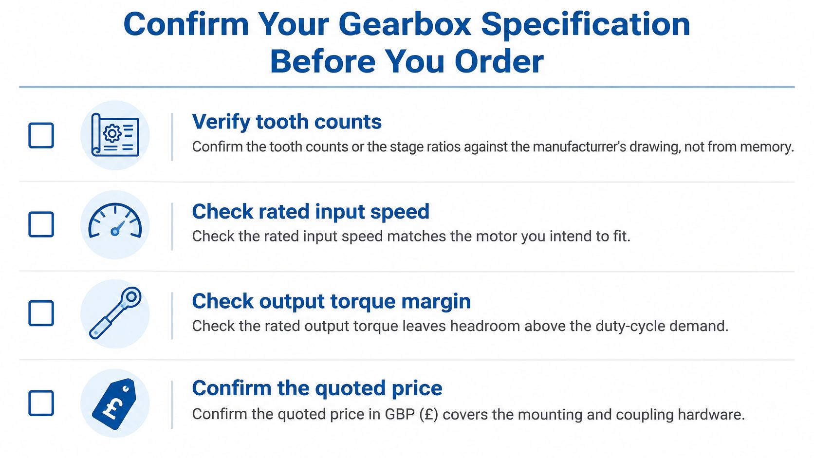
- Verify tooth counts. Confirm the stage ratios against the manufacturer's drawing and record its revision.
- Check speed limits. Match the rated input speed to the proposed motor, and compare the calculated 90.6 rpm output with the machine's permitted operating speed.
- Check torque margin. Assess the 589.8 N·m operating result against continuous and peak ratings, with the manufacturer's service-factor method applied to the actual duty.
- Recalculate before release. Retain unrounded ratios and confirm that any small power-balance discrepancy comes from display rounding, not an unexplained loss.
- Record the commercial basis. Keep the quotation date, GBP currency basis and the inclusion or exclusion of VAT, delivery, installation, mounting hardware and couplings.
The checklist below provides a visual reminder, but the written specification should remain the purchasing reference.
Make the specification usable on site
Include shaft dimensions, mounting orientation, permitted external shaft loads and lubrication requirements. Check the motor's ability to deliver the required operating point using the motor sizing guide, rather than assuming that a compatible flange means a compatible drive.
For ongoing inspection planning, Forge Reliability's industrial gearbox reliability monitoring provides relevant context for monitoring the installed equipment. Keep commissioning readings with the specification so maintenance staff have a baseline for comparison.
Technical presentation also needs checking. UK Government accessibility guidance identifies WCAG 2.2 Level AA as the public-sector benchmark, organised around perceivable, operable, understandable and resilient content. It's a useful quality benchmark for engineering documents, without implying that every commercial page has the same public-sector obligations.
Proofread image wording against the calculation sheet. If a demonstration video accompanies the specification, test its frame on desktop, tablet and mobile so formulas aren't cropped; the Government publishing guidance for videos recommends switchable closed captions and an accompanying HTML transcript.
At MA Hydraulics Ltd, we stock Borelli and KRS aluminium and cast iron agricultural PTO gearboxes, reduction gearboxes, lever operated clutches and electro-mechanical clutches. We use our extensive databases to offer alternative solutions at competitive prices when the required ratio, mounting arrangement or torque rating points to a different unit.
Bring your input speed, required output speed, torque calculation and duty details to MA Hydraulics Ltd for help matching a gearbox or alternative transmission solution to the application. Phone 01724 279508 today, or send us a message with your drawing and calculated figures so we can help you check the selection before ordering.
