

A single hydraulic pump often ends up doing too much. On a tractor, telehandler, access platform, or compact industrial machine, that one pump may need to feed steering, braking, and an auxiliary service at the same time. The trouble starts when the auxiliary load rises and the operator still expects the critical function to feel normal.
That's where a priority flow divider valve earns its place. It isn't just a splitter. It is a control device that protects one branch of the circuit first, then sends whatever flow remains to the secondary branch. In practice, that difference is what keeps steering available when another function is demanding oil.
Engineers often get the basic idea quickly but still run into problems when they have to specify, set, and commission the valve on a real machine. The hard part isn't recognising what the valve does. The hard part is deciding when it's the right architecture, sizing it around the actual pump and duty cycle, and avoiding a system that runs hot or feels sluggish in service.
Introduction to Hydraulic System Flow Management
A lot of hydraulic design comes down to one question. Which function must never be starved of flow?
On mobile machinery, the answer is usually obvious. Steering has to work. Braking-related services have to work. On some industrial equipment, a clamp circuit, lubrication feed, or core process function has to remain stable even while another actuator sees changing demand.
A priority flow divider valve solves that by letting one pump feed two branches while preserving a preferred function first. In a peer-reviewed technical paper on the priority flow divider valve, the valve is described as dividing pump output into a primary and secondary path, with the primary port adjusted according to load while excess flow passes to the secondary port. The same paper notes applications from vehicle steering to hydrostatic power transmission in wind turbines, which is a useful reminder that this isn't a niche mobile-only component.
Why this matters on UK machinery
In UK agriculture, construction, and materials handling, single-pump systems are still common because they keep packaging and cost under control. That's sensible. But once one pump is serving more than one job, the circuit has to decide what gets oil first.
Practical rule: If loss of flow to one branch would make the machine unsafe or unusable, that branch should be treated as the priority circuit.
The same technical paper also notes that a pressure relief valve is commonly fitted between the pump and the priority flow divider valve as a safety device. This underscores their significance, as these valves are part of a protected hydraulic system, not just a convenient plumbing shortcut.
What engineers usually get wrong
Most mistakes happen in three places:
- Treating it like a simple tee fitting: A priority valve manages flow under changing load. A tee does not.
- Sizing it around the actuator instead of the pump: The valve has to cope with the pump's delivery, not just the preferred service.
- Ignoring the duty cycle: A circuit that works on paper can still waste energy if excess flow is regularly dumped instead of used productively.
How a Priority Flow Divider Valve Works
The easiest way to think about a priority flow divider valve is a two-lane road where emergency traffic always gets a clear lane first. The second lane only gets whatever capacity is left. In hydraulics, the emergency lane is the priority port, and the other lane is the excess port.
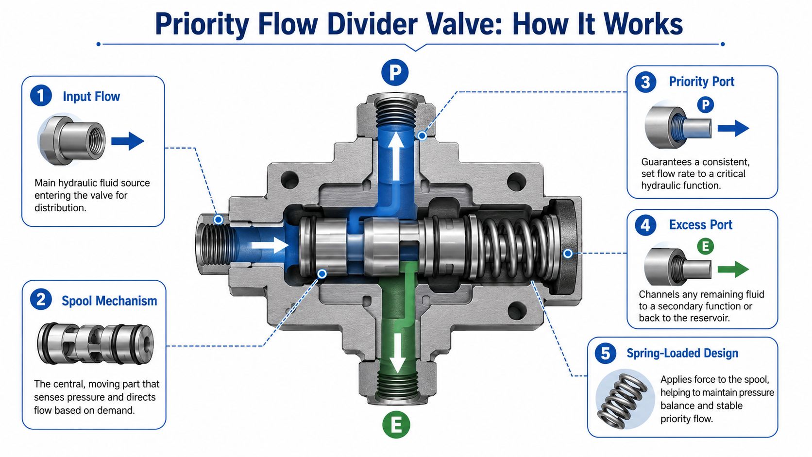
The internal logic
Inside the valve, a pressure-compensating spool reacts to pressure conditions and adjusts the internal restriction so the priority branch receives its set flow first. If pump flow rises above that requirement, the balance goes out through the excess port. If demand on the secondary branch changes, the spool acts to protect the priority side before anything else.
That's the point many simplified explanations miss. A priority flow divider valve doesn't merely split flow in half or in a fixed ratio. It holds the priority stream first and only passes surplus flow onward.
What that means in service
On a steering and auxiliary circuit, the steering branch should remain predictable even when the auxiliary branch sees a heavier load. The valve's job is to stop that secondary load from robbing the preferred circuit of flow.
This is why the component shows up so often in machines where operator control depends on one function staying alive. A steering wheel that suddenly goes heavy because another service demanded oil is not a minor tuning issue. It's a design failure.
Keep the mental model simple. Pump flow enters once, the valve protects one branch first, and the rest is released to the second branch only after the priority demand is satisfied.
Pressure, spool movement, and stability
The spring-loaded arrangement matters because it helps the spool find a stable position as load pressure changes. When the system is healthy, that movement is controlled and repeatable. When the oil is dirty, the spool is sticking, or the valve is badly matched to the circuit, you tend to see hunting, heat, and inconsistent response.
A well-laid-out system also places protection where it belongs. In practice, relief protection upstream of the valve is common because it protects the pump and valve assembly when pressure rises beyond the intended operating condition.
What it does not do
It doesn't make a poor pump look good. It doesn't fix a circuit that is permanently short of flow. And it doesn't remove the need to think about where excess flow goes.
If the pump can't provide enough oil for the priority demand, the valve can only preserve what is available for that branch. The secondary branch will get less, or none.
Common Types and Configurations of Priority Dividers
By the time you're choosing hardware, the principle is no longer the challenge. The challenge is selecting the form that suits the machine, the plumbing, and the service conditions.
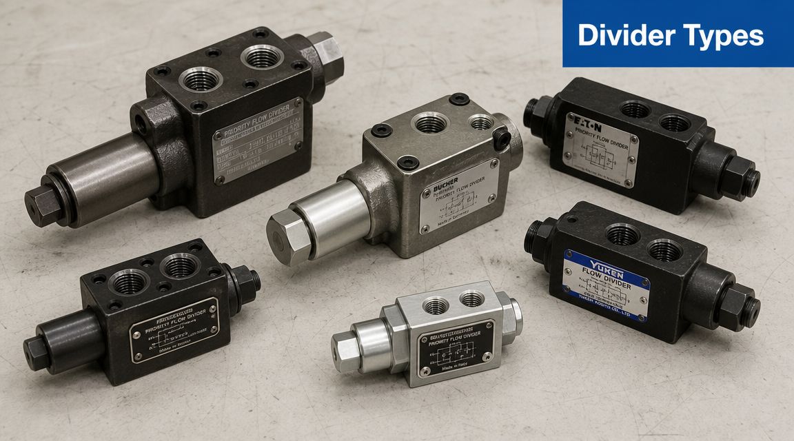
Inline bodies and cartridge designs
Some priority dividers come as inline valves with dedicated ports and a self-contained body. These are common on mobile equipment and retrofit work because they're straightforward to pipe and easy to replace.
Others come as cartridge valves intended for manifold installation. These suit OEM builds where compact packaging, fewer hose runs, and cleaner manifold logic matter more than stand-alone serviceability.
In broad terms:
- Inline valves suit field replacements, lower-volume builds, and systems where visibility and access matter.
- Cartridge valves suit compact manifolds, neater layouts, and machines where the hydraulic block is designed around the control logic from the start.
Fixed-flow and adjustable versions
A fixed-flow priority valve is the right choice when the critical service requirement is known and unlikely to change. Steering circuits are a good example. Once the flow need is established, many designers prefer a fixed setting because it removes one adjustment that can drift or be altered in the field.
An adjustable valve makes sense where the machine may be configured in more than one way, or where commissioning needs some tuning on site. That flexibility is useful, but it comes with responsibility. If the setting is wrong, the whole machine can feel compromised even though no part is broken.
Adjustable valves are useful. They're also easy to mis-set. If the application is safety-related, keep the adjustment controlled and documented.
Relief integration and control strategy
Some systems benefit from a separate relief arrangement. Others are tidier with valve configurations that simplify the surrounding circuit. The best choice depends on how much of the protection and control logic you want concentrated in the valve assembly versus elsewhere in the hydraulic block.
Published distributor information for Eaton's load-sensing priority valves states that sizing is based on the design pressure drop at maximum pump output flow rate and the required priority flow, and that the valve provides dependable flow on demand for steering, braking, or other priority functions while allowing excess flow to serve auxiliary functions, as shown in Eaton priority valve documentation distributed in the UK. The same documentation also includes practical published hardware figures, including Muncie's PFD-30 at 114 L/min priority flow and 207 bar maximum pressure.
Those figures don't tell you which configuration to buy on their own, but they do anchor the selection process in real component limits rather than guesswork.
Selecting and Sizing Your Valve Correctly
Most selection errors happen before the valve is ever fitted. People pick a unit that seems close to the actuator requirement, then wonder why the machine behaves poorly when another service comes in. A priority flow divider valve has to be sized as part of the whole circuit.
Start with the pump, not the cylinder
This is the first discipline. Size around maximum pump delivery and the required priority flow setpoint. Don't size around what the actuator usually does on a calm day.
A good reference point appears in Eaton and PSI Fluid Power priority flow divider data, where a specification shows 175 L/min rated input flow and 135 L/min maximum controlled flow. That illustrates the design logic. The valve is selected around the pump's maximum delivery and the amount of flow that must be protected for the priority branch.
The selection checklist
Use a shortlist before you even compare brands.
| Parameter | Consideration | Unit of Measure |
|---|---|---|
| Pump maximum delivery | Must not exceed the valve’s rated inlet capability | L/min |
| Priority flow requirement | Flow that the protected circuit must receive first | L/min |
| Maximum system pressure | Must sit within the valve’s pressure rating | bar |
| Pressure drop | Check the datasheet and account for losses through the valve | bar |
| Porting and mounting | Inline body, cartridge cavity, hose and manifold layout | N/A |
| Adjustment type | Fixed setting or field adjustable | N/A |
| Excess flow destination | Productive secondary use or return path | N/A |
| Relief strategy | Upstream protection and branch protection arrangement | bar |
What to confirm on the datasheet
A valve can look suitable until you read the small print. The details that matter are usually these:
- Inlet capacity: It has to tolerate the pump at full delivery, not just average machine use.
- Controlled flow range: Make sure the priority setting sits comfortably within the valve's intended range.
- Pressure rating: Check the maximum continuous pressure against the actual circuit, including spikes and normal working conditions.
- Pressure drop characteristics: If the valve introduces unnecessary restriction, the system pays for that in heat and response.
- Port identification: Confirm P, CF, EF, or equivalent notation before plumbing. Assumptions create expensive faults.
The practical sizing trap
A common trap is asking, “How much flow does the steering ram consume?” and stopping there. That question matters, but it's incomplete. The valve has to handle what the pump can deliver into it, while guaranteeing what the priority branch must keep.
Size the valve for the pump at its most generous, and set the priority branch for the minimum flow the critical function needs to remain dependable.
That approach is far more effective than trying to fine-tune the whole machine around a barely adequate valve.
Match the duty cycle, not just the schematic
A priority divider that looks perfectly sensible on a simple line diagram may still be wrong for the job if the machine spends long periods sending excess flow somewhere unhelpful. If the secondary branch can use the oil productively, the architecture is often very effective. If the excess is repeatedly forced across a relief path, efficiency suffers and heat follows.
That's why selection is never just a valve catalogue exercise. It's a system decision.
Installation and Maintenance Best Practices
Installation quality often decides whether the valve feels precise or troublesome. A properly selected priority flow divider valve can still underperform if the plumbing is careless, the commissioning is rushed, or contamination is allowed into the spool.
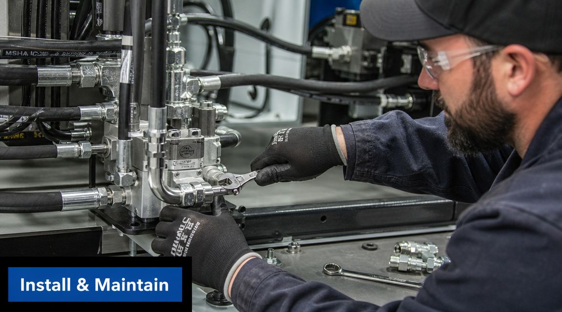
Get the porting right first time
This sounds obvious, but it's where avoidable faults begin. Confirm the inlet, priority, and excess ports from the actual valve documentation and body markings. Don't rely on memory from a different model.
A few installation habits make a real difference:
- Keep the valve close to the relevant control section: Long unnecessary hose runs add restriction and create extra places for leaks and pressure loss.
- Support the pipework properly: Heavy hoses pulling on the body can create fatigue and nuisance leaks.
- Flush the circuit before commissioning: A compensating spool doesn't tolerate contamination well.
- Protect the upstream side: Relief strategy and filtration need to be thought through before the machine is started.
Commissioning adjustable models
An adjustable priority valve shouldn't be set by feel alone. Use a flow meter and verify the controlled branch under representative operating conditions. If you only set it at idle or with no real load on the machine, you may end up with a priority setting that falls apart in service.
Guidance discussed by Machinery Lubrication on hydraulic flow dividers notes that pressure settings are often chosen with a margin of roughly 14 to 28 bar above the pressure needed to move the heaviest load. That's useful as a commissioning reference point, but it doesn't replace tuning the circuit for the actual duty cycle.
A valve that is technically “set” is not necessarily well tuned. The machine has to be checked across the way it really works, not only at one static condition.
A useful visual overview of setup and flow control practice is below.
What to watch in service
When a priority divider is healthy, the protected function feels stable. When it isn't, the symptoms are usually familiar.
| Symptom | Likely cause | First check |
|---|---|---|
| Priority function feels weak | Incorrect setting or inadequate pump flow | Verify actual flow at the priority port |
| Secondary function is dead too often | Priority set too high or pump undersized | Check valve setting against duty requirement |
| System runs hot | Excess flow wasted or pressure loss too high | Review excess path and pressure drop |
| Noisy operation | Aeration, restriction, or contamination | Inspect suction side, oil condition, and filters |
| Unstable response | Sticking spool or load-related instability | Check cleanliness and operating conditions |
Maintenance that pays back
Routine maintenance is not glamorous, but it keeps these valves predictable. Clean oil, correct filtration, and periodic verification of the setting matter more than repeated adjustment. If a machine suddenly needs frequent re-tuning, look for the fault elsewhere first. Worn pumps, relief issues, contamination, and hose restrictions often get blamed on the priority valve.
For replacement components and flow-divider options, one UK source engineers may already know is the MA Hydraulics flow dividers range, alongside other catalogue and OEM supply routes.
Typical Applications and System Alternatives
The best applications for a priority flow divider valve are the ones where one function must stay dependable while another can live on surplus flow. That sounds simple, but it's a strong filter for deciding whether this architecture fits.
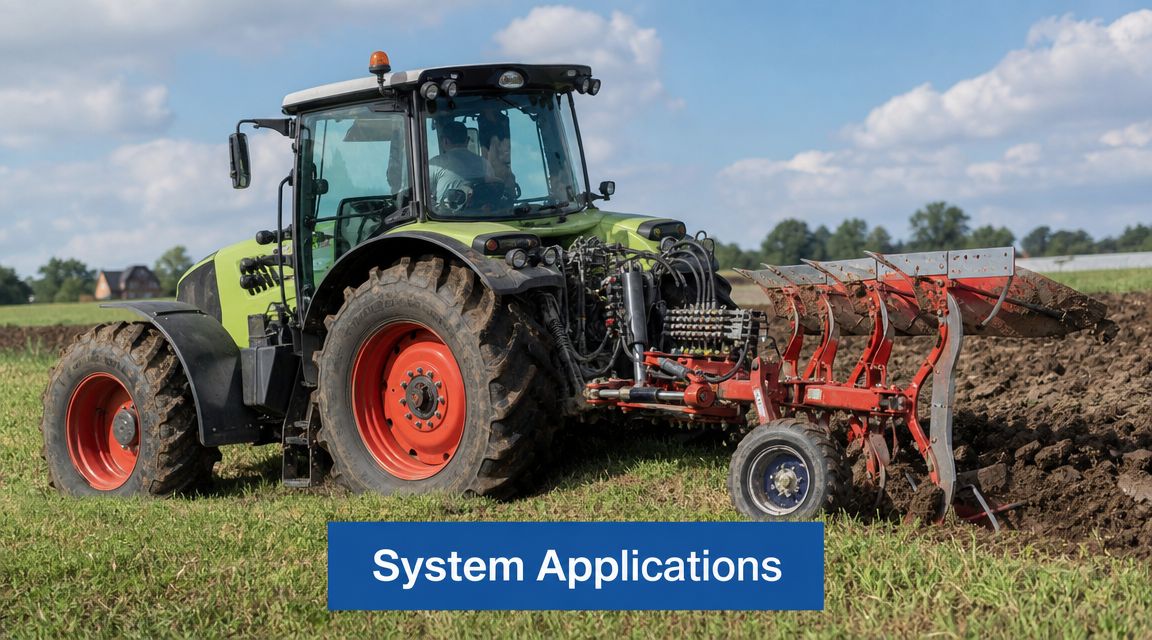
Where it makes good engineering sense
On agricultural machinery, steering often needs priority while loader, linkage, or auxiliary services use the remainder. In materials handling, steering may come first while mast or attachment functions take excess flow. In compact industrial plant, a machine may need one stable service while a secondary actuator cycles according to operator demand.
These are strong use cases because the machine can tolerate variable performance on the secondary branch, but not on the primary one.
Where it becomes a poor fit
The architecture becomes less attractive when excess flow is routinely wasted. If the secondary branch frequently dumps flow across a relief valve, the system turns energy into heat instead of productive work.
That's the point where a more advanced pump strategy starts to deserve attention. Sun Hydraulics notes in its technical description of priority flow control that priority flow can be achieved with very low pressure losses across the valve elements, but whole-system efficiency is a separate question. If bypassed flow is repeatedly wasted, a variable-displacement or load-sensing pump system may deliver a lower total cost of ownership over long duty cycles.
Component efficiency and system efficiency are not the same thing. A good valve can still sit in a poor overall architecture.
Comparing the main options
Here's the practical comparison engineers usually care about most:
-
Priority flow divider valve with one pump
- Lower system complexity
- Useful where one branch must always come first
- Good fit when excess flow is still put to work
- Can create heat if the excess path is poorly managed
-
Two dedicated pumps
- Cleaner separation between functions
- More hardware, more packaging, more cost
- Often justified when both branches are critical
-
Load-sensing or variable-displacement pump system
- Better potential efficiency on variable duty cycles
- Higher system complexity and cost
- Worth serious consideration where energy use and heat rejection are major concerns
The honest decision point
If the machine is simple, space is tight, and one service must be protected from another, a priority divider is often the right answer. If the machine spends long periods circulating unused oil or fighting relief losses, the cheap option at purchase can become the expensive option in service.
That's why this choice should be made with the duty cycle in mind, not just the schematic.
Your Partner for Hydraulic System Components
A priority flow divider valve is one of the most practical ways to run two hydraulic branches from one pump while protecting the service that matters most. When it's chosen and set properly, it gives a compact system a clear hierarchy. The machine keeps its critical function, and the remaining flow is still available for useful work.
The value is in the detail. Correct sizing around pump delivery, realistic commissioning, clean installation, and an honest look at energy losses are what separate a reliable circuit from one that creates constant complaints.
For engineers, OEMs, maintenance teams, and repair businesses, component selection often comes down to matching the valve to the machine's actual working pattern rather than its idealised drawing. That's where experienced hydraulic support is useful, especially when you're balancing reliability, packaging, and operating cost on the same project.
If you need help selecting a priority flow divider valve or matching hydraulic components for a mobile or industrial system, contact MA Hydraulics Ltd. Phone 01724 279508 today, or send us a message through the contact form.
