
A lot of hydraulic failures don't start with bad components. They start on the day of first startup, when a new installation is finally piped, wired and filled, and someone is tempted to prove it by switching it on too early. That's the moment when a small leak becomes a soaked plant room, trapped air becomes pump damage, and a missed drawing discrepancy becomes an expensive shutdown.
Good testing and commissioning isn't a paperwork exercise. It's a controlled risk-reduction process. Every check has a purpose. Every hold point is there to catch something while it's still cheap, safe and straightforward to correct.
If you're standing in front of a new hydraulic system before first energisation, think like a commissioning engineer, not just an installer. You're not trying to make it run once. You're proving that it will run safely, predictably and within design intent. That means documents first, then isolation, then integrity checks, then staged pressure testing, then cold functional proving, then loaded performance verification, then formal handover. In practice, the discipline you apply here has more influence on long-term reliability than is often appreciated.
The Foundation of a Successful Hydraulic System Startup
The first startup of a hydraulic system tells you two things very quickly. It tells you whether the build is sound, and it tells you whether the team has treated commissioning as engineering or as theatre.
A rushed startup usually has the same pattern. Pipework looks complete, the reservoir is filled, gauges are fitted, and everyone assumes the rest can be sorted live. That approach is where trouble starts. Hydraulic systems store energy, hide contamination, trap air, and punish careless sequencing. When a fault appears under pressure, you've already moved from prevention into damage control.
A proper testing and commissioning process changes that. It breaks startup into manageable proof stages, each one designed to remove a class of risk before the next begins. Static checks prove the installation matches the design. Pressure and leak testing prove containment. Dynamic testing proves motion, control logic and thermal behaviour. Final acceptance proves that what has been built can be operated, maintained and legally documented.
Practical rule: Never use first energisation as your main fault-finding method. Find installation errors while the system is isolated, and find integrity issues before oil is circulated under working load.
This matters for three reasons.
First, safety. A hydraulic fault under pressure doesn't give much warning. Second, cost. A loose fitting caught during a staged test is a minor delay. The same fitting missed until full operation can damage pumps, seals, finished surfaces and production schedules. Third, compliance. In the UK, pressure systems and associated examinations are tied to formal duties, and handover has to stand up to scrutiny later.
The best commissioning engineers work backwards from failure. They ask what could leak, cavitate, overheat, bind, drift, or be rejected at handover, then they build the startup sequence to catch those failure modes in order. That's the difference between a checklist mentality and a risk-mitigation framework. One records steps. The other prevents expensive mistakes.
Pre-Commissioning Inspections and Safety Protocols
Before any pressurisation, the system needs to be treated as incomplete until proven otherwise. That starts with documents, not tools. If the paperwork is wrong, the physical checks often follow the wrong assumptions.
Start with drawings and the legal baseline
Check the P&ID, general arrangement drawings, component lists, hose schedules, valve settings, filtration requirements and control philosophy against what's installed. If the drawing shows one relief valve setting and the machine has another, don't assume the workshop made a harmless substitution. Stop and resolve it.
This is also the point to confirm whether the system falls under the UK pressure system rules that require formal examination. Under the UK Pressure Systems Safety Regulations 2000, a Written Scheme of Examination is mandatory before operating any qualifying pressure system, defined as equipment containing steam at any pressure or a relevant fluid at stored pressure above 0.5 bar with an internal volume exceeding 250 bar-litres (Loughborough University guidance on pressure system safety policy).
For younger engineers, discipline proves valuable. Don't rely on memory. Mark up discrepancies and create a punch list before any test medium is introduced.
If you want a practical cross-trade prompt sheet before walking a site, BIM Heroes' inspection checklist is useful for structuring the visual inspection around access, finish quality and installation readiness. For hydraulic-specific build checks, a set of installation guidelines for hydraulic systems helps keep supports, routing and component orientation in focus.
Then inspect the installation as if it will fail
Physical pre-commissioning inspection should be systematic. I'd normally walk it in this order:
- Supports and restraint: Pipework must be properly supported, protected from vibration and free from unintended strain at valves, manifolds and machine connections.
- Accessibility: You need clear access to gauges, test points, drain points, isolation valves and likely leak paths. If you can't inspect it, you can't prove it.
- Cleanliness: Remove blanks, transit plugs, rags, swarf, tape fragments and debris. A clean system isn't a nice extra. It's part of preserving pumps, valves and seals.
- Component orientation: Filters, coolers, check valves, flow controls and case drain lines need to be installed in the correct direction and position.
- Fluid readiness: Confirm the specified fluid is available, correctly identified and suitable for the system.
Isolate before anyone gets clever
No one should energise a motor, crack open a valve or override a control while checks are under way. Isolation and lock-off need to be clear, visible and enforced. Mechanical, hydraulic and electrical stored energy all count. Lockout, tagout and controlled access aren't bureaucracy. They prevent the worst kind of commissioning incident, where one person is inspecting and another person assumes the system is ready.
A good pre-commissioning inspection feels slow. That's a sign it's being done properly.
One more point. Confirm responsibilities before testing starts. Who owns the gauges, who signs the test record, who authorises corrective work, and who decides whether the system proceeds or stops. Ambiguity here causes bad decisions later.
Executing a Systematic Pressure and Leak Test
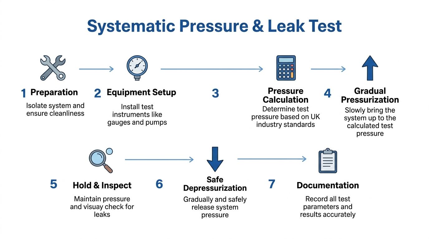
Pressure testing is where the installation stops being assumed safe and starts being proven safe. This isn't the stage for bravado. It's the stage for control, patience and accurate recording.
Calculate the correct test pressure
In UK hydraulic pipework systems, the standard hydraulic testing pressure is exactly 1.5 times the Maximum Working System Pressure, using the formula HTP = MWSP x 1.5, as mandated by BESA TR/6. For critical systems, the test pressure must be maintained for a minimum of 1 hour with +/-0% pressure drop (Construct and Commission guidance on pressure testing pipework systems).
That figure isn't arbitrary. It creates a controlled proof margin above working conditions so you can validate joints, manifolds, fabricated sections and interfaces before service loads are introduced.
For a practical reference on staged hydraulic test execution and test records, use these pressure testing procedures for hydraulic systems.
Raise pressure in stages, never in one sweep
One of the easiest mistakes to make is going from fill condition straight to full test pressure. Don't do it. When testing hydraulic systems to UK standards such as BS EN ISO 4413, pressure should be raised in deliberate stages with intermediate holds, with the gauge continuously monitored during the full-pressure hold (MA Hydraulics pressure testing procedures).
A sound sequence looks like this:
-
Fill and vent the boundary
Bleed trapped air from high points and dead legs. Air makes readings less stable and can mask faults. -
Apply a low preliminary pressure
Bring the system up gently for an initial clean check. At this stage, you're looking for obvious mistakes like a loose adaptor, missing plug or badly seated fitting. -
Pause and inspect
Walk the accessible joints, manifolds and valve interfaces carefully. White rag checks are still one of the best ways to spot a faint weep. -
Increase in controlled stages
Move upward with deliberate pauses. The point of the hold isn't to waste time. It's to let defects show themselves before the system is stressed further. -
Hold at final test pressure
Maintain the specified pressure for the required period and watch the gauge continuously. -
Depressurise safely
Bring pressure down in a controlled manner. Sudden release can create its own problems.
Choose the right test medium for the risk
The test medium matters. In UK hydraulic commissioning, dry testing using air pressurisation at 110 mbar is strongly recommended over water-based leak testing unless the system will be operational immediately after test. The dry-test duration is 30 minutes for 100 litres of pipework capacity, increasing by 10 minutes per additional 100 litres, and a recordable pressure drop indicates a leak. Following that dry-testing protocol is associated with lower post-handover corrosion and contamination issues, while water-based testing without immediate flushing is associated with higher corrosion and blockage rates (CIBSE Journal pipework commissioning considerations).
The trade-off is straightforward:
| Test medium | Where it helps | Where it creates risk |
|---|---|---|
| Dry air | Useful when the system won’t enter immediate service and internal cleanliness matters | Requires careful leak interpretation and controlled low-pressure practice |
| Water | Suitable where immediate post-test flushing and prompt service are planned | Can leave corrosion and contamination behind if the process is not completed properly |
Don't choose the test medium because it's familiar. Choose it based on what the system will do after the test.
If the pressure hold fails, don't chase the gauge first. Confirm temperature stability, venting completeness, instrument accuracy and isolation integrity. Then inspect the hardware again. The leak is usually where access was awkward, visibility was poor or someone assumed a threaded connection was “tight enough”.
Dynamic Functional Testing and Performance Validation
Static integrity tells you the system can contain pressure. It doesn't tell you whether it can behave properly once the pump turns, the oil warms and actuators begin to move. That's why the next phase has to be calm and deliberate.
Bring the system online as if you expect to learn something from the first few minutes, because you will.

Start cold and unloaded
Expert technical specifications for UK hydraulic pump commissioning require cooling the system under no-load conditions first, then slowly increasing load pressure once operating temperature is reached, while monitoring housing temperatures of pumps and motors with a limit of ≤85°C. A common pitfall is neglecting incremental load increases, which causes 40% of premature pump seal failures (Motion, Drives & Controls guidance on testing and commissioning for engineering projects).
That requirement matches what experienced engineers see in practice. A cold, unloaded start gives you the best chance to catch trapped air, poor suction conditions, reversed rotation, low reservoir level, incorrect valve positions and unstable controls before those issues are amplified by load.
During the first live run, focus on what the system is telling you:
- Listen for cavitation or bearing distress: Harsh noise, crackle or growl shouldn't be explained away as “new pump noise”.
- Watch fluid level behaviour: Sudden drop, foaming or erratic return suggests air movement or poor reservoir conditions.
- Check for smooth actuator response: Jerky motion often points to entrained air, binding, flow restriction or control instability.
- Track temperatures early: Heat rise begins the moment inefficiency is present.
Add load slowly and make the system settle
Inexperienced teams often undo a good pressure test. They've proved containment, then jump straight to high load because the machine “needs a proper run”. That shortcut is hard on seals, couplings, case drain paths and relief settings.
Instead, apply load progressively and let the system stabilise at each step. With mineral oils, you're typically looking to reach operating temperature in the 45 to 60°C range before judging how the machine behaves under its intended duty, as set out in the same technical guidance above.
I usually want to see each stage answer a specific question:
| Load stage | What you’re proving |
|---|---|
| No-load operation | Correct rotation, priming, venting, control wake-up, base noise level |
| Low load | Stable pressure build-up, predictable valve behaviour, no sudden heat rise |
| Intermediate load | Repeatable actuator performance, acceptable temperature trend, no drift or chatter |
| Duty load | Performance at intended working condition without instability or abnormal temperature |
A staged approach also protects your diagnosis. If a fault appears only after a temperature rise, you know where to focus. If it appears immediately at first load, the cause is usually simpler.
Here's a useful visual reference for what controlled startup and live monitoring should feel like in the field.
Validate performance, not just movement
A system that moves isn't necessarily a commissioned system. You need to verify that it performs as designed. That includes pressure stability, cycle repeatability, commanded speeds, neutral behaviour, relief performance, emergency stop response and safe shutdown.
Acceptance testing in electrical commissioning is commonly carried out alongside commissioning to verify that individual components match the original design documents and manufacturer requirements before energisation, and that same mindset helps with hydraulics as well. It keeps you anchored to design intent rather than seat-of-the-pants judgement.
If a system only works when a skilled engineer “nurses” it through startup, it isn't commissioned yet.
This is also the point where component selection starts to show its value. For bespoke packs and integrated systems, options such as MA Hydraulics Ltd can supply assembled power packs and application support for industrial and mobile setups, but regardless of supplier, the commissioning standard has to remain the same. The system must prove itself under controlled operating conditions, not by optimism.
Instrumentation Calibration and Troubleshooting Common Faults
Bad commissioning data creates bad decisions. If the gauge is wrong, the thermocouple is drifting or the transducer wasn't verified, you can spend hours chasing a fault that isn't there while missing the one that is.
That's why instrument confidence comes before fault diagnosis. Trust, then test.
Calibrate before you interpret
A benchmark success rate for integrated hydraulic commissioning in UK engineering projects is 92% when performance testing and safety testing are conducted as required, and omitting sequential table checks against actual installation accounts for 37% of commissioning retests and delays (CIBSE Journal technical guidance on pipework commissioning considerations).
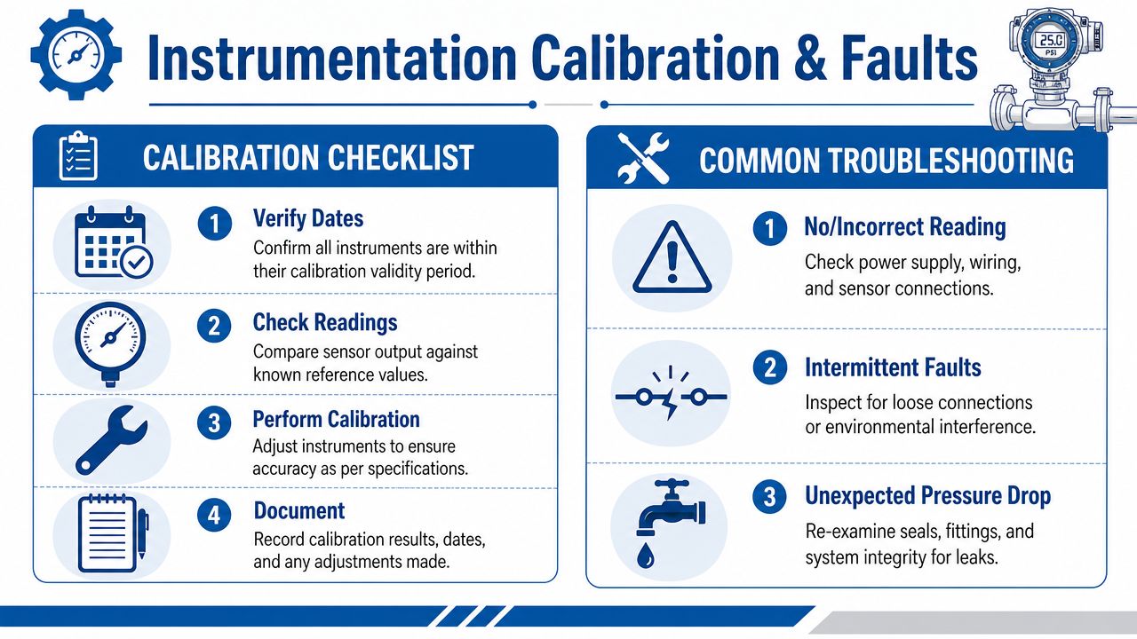
The lesson is simple. Method beats speed. Before relying on any reading, confirm:
- Calibration validity: Is the instrument within its valid period?
- Suitability: Is the range correct for the expected duty?
- Reference check: Does it agree with a known good instrument or reference condition?
- Installation quality: Are leads, impulse lines, connectors and mounting points secure?
Use a fault path, not guesswork
When a commissioning test fails, don't bounce between components at random. Start with the simplest sensory checks and move outward in a fixed order.
Field note: Sight, sound, smell and touch still matter. Instruments confirm a problem. They don't replace observation.
A practical troubleshooting sequence looks like this:
System won't build pressure
Check fluid level, suction condition, pump rotation, relief valve position and any obvious open return path first. Then verify whether the pressure reading itself is trustworthy. A failed gauge has wasted many hours on perfectly healthy pumps.
Actuators are slow or erratic
Look for trapped air, unstable flow control, contamination, sticking spool movement, blocked filters or an undersupplied suction side. If the behaviour changes as oil warms, note exactly when that happens. Thermal dependence is a clue.
System is overheating
Confirm cooler operation, bypass settings, sustained relief flow, case drain behaviour and whether the machine is being held against end stops. Overheating is often a symptom of energy being dumped somewhere it shouldn't be.
Match troubleshooting to installation reality
The reason sequential checks work is that most commissioning faults aren't exotic. They're ordinary installation issues presenting under live conditions. Wrong setting. Wrong orientation. Wrong connection. Air left in the line. Sensor not reading correctly. Drawing not updated.
A short comparison helps:
| Symptom | First place to look | Why it’s often missed |
|---|---|---|
| Unexpected pressure drop | Seals, fittings, manifold interfaces | Access is awkward and small weeps are easy to miss |
| Intermittent readings | Wiring, loose connectors, environmental interference | The signal fault appears to be a process fault |
| Poor response | Air, contamination, restriction, unstable controls | Teams jump to pump replacement too quickly |
The discipline here is to prove each layer before moving on. When junior engineers learn that habit early, they stop treating commissioning as firefighting and start using it as diagnosis.
Final Acceptance Criteria and Handover Documentation
The system isn't finished because it ran for an hour without drama. It's finished when the results are documented, the exceptions are closed, and the client can operate and maintain it without relying on verbal handover.
Define acceptance against the original intent
Final acceptance should tie back to design documents, agreed operating conditions and recorded test outcomes. That means the installed system matches the approved build, the pressure and leak test has passed, dynamic functional checks are complete, protective functions have been verified, and any outstanding defects are either corrected or formally listed with agreed action.
A clean handover pack should include:
- As-built drawings: Updated to reflect the actual installed arrangement.
- Test records: Pressure test documentation, leak test observations and commissioning sign-offs.
- Component information: Datasheets, manuals and settings relevant to operation and maintenance.
- Maintenance essentials: Filters, seal kits, wear parts and recommended spares.
- Operating record: Final commissioning report with observations, constraints and accepted performance.
Fluid condition should also be captured where relevant. If the client inherits a system with poor cleanliness evidence, future faults become harder to diagnose. For that reason, it's sensible to include guidance aligned with hydraulic fluid cleanliness standards as part of the handover file when contamination control is critical to service life.
Don't neglect the formal examination report
Per UK PSSR requirements, a competent person must issue an examination report within 28 days of completion, and that report must specify the date for the next examination, identify any necessary repairs or modifications, and state their opinion on the continuing suitability of the scheme of examination to prevent danger (AI Solutions overview of Pressure Systems Safety Regulations 2000).
That timing matters. Handover isn't just a technical milestone. It has regulatory consequences.
If the system is one that requires periodic examination, future planning should also be made visible at handover. Suggested examination intervals under UK guidance are typically 12 to 14 months, though Class C equipment may be scheduled up to a maximum of 72 months where conditions justify it (SAFed guidance on periodicity of examinations). That belongs in the maintenance conversation from day one, not months later when dates are already drifting.
Handover should make future work easier
A good handover file helps the next engineer answer practical questions quickly. What was the test pressure? What settings were accepted? Which components were fitted? What repairs were made during commissioning? When is the next examination due?
Here's the standard I'd aim for:
| Handover item | Why it matters |
|---|---|
| Accurate as-builts | Prevents future maintenance based on obsolete drawings |
| Complete test evidence | Proves integrity and supports dispute resolution |
| Component manuals and settings | Reduces service errors and wrong-part replacements |
| Formal examination paperwork | Supports legal compliance and future scheduling |
The client shouldn't need the commissioning team on speakerphone six months later to understand what was installed.
That's the genuine test of handover quality.
Partner with Hydraulic Commissioning Experts
Testing and commissioning is where a hydraulic project either gains reliability or inherits hidden problems. The structured approach is always the safer one. Inspect first. Isolate properly. Prove containment. Start cold. Add load in stages. Trust instruments only after calibration checks. Then document everything well enough that the next engineer can maintain the system with confidence.
That approach doesn't just reduce immediate risk. It protects pumps, seals, valves, pipework and production uptime over the life of the installation. It also gives owners and maintenance teams something they can rely on after the commissioning team has left site.
If you need support with hydraulic testing procedures, bespoke power packs, component selection or practical commissioning advice for an industrial or mobile application, specialist help usually saves time and rework.
If you need support from MA Hydraulics Ltd, phone 01724 279508 today or send us a message.
