A tractor loader slows on a cold morning. A forklift starts to sound harsh when lifting at full height. A factory press loses consistency halfway through a shift. In many of these cases, the fault trail leads back to one small component that does a very big job: the gear pump.
If you work around hydraulic machinery long enough, you stop thinking of the pump as just another catalogue item. It is the part that turns shaft rotation into usable oil flow. Get that right and the rest of the circuit has a chance to perform properly. Get it wrong, and every valve, cylinder and motor downstream is forced to work with unstable flow, heat and contamination.
That’s why the question how does a gear pump work matters beyond theory. A proper answer helps with fault-finding, sizing, pump selection and service planning. It also explains why some machines tolerate abuse for years while others eat seals, lose pressure and come back for repair far too often.
The Unseen Heart of Hydraulic Machinery
A gear pump usually doesn’t get much attention until the machine stops earning. Operators notice the ram slowing down, the steering going heavy, or the attachment movement becoming erratic. The pump has already been working in the background the whole time, driven by an engine or electric motor, feeding the circuit every revolution.
In practical terms, a gear pump is a positive displacement pump. That matters because it doesn’t “spin up pressure” by itself. It moves a fixed quantity of fluid per revolution, and the system creates pressure when that flow meets resistance at a cylinder, motor, valve or load. That single point clears up a lot of confusion on site.
Practical rule: If the pump is producing flow and the actuator still won’t move correctly, don’t blame the pump first. Check what in the circuit is resisting, bypassing or starving that flow.
Gear pumps are common in UK agriculture, mobile plant, materials handling and industrial power packs because the design is straightforward and dependable. They suit work where engineers need compact size, predictable delivery and serviceable hardware rather than unnecessary complexity.
The true value in understanding the pump isn’t the textbook definition. It’s knowing why inlet conditions matter, why internal wear shows up first as lost performance, and why two pumps that look similar on the bench can behave very differently once they’re fitted into a machine. Those are the details that separate a clean installation from a repeat breakdown.
The Core Mechanism How Gear Pumps Move Fluid
A gear pump moves oil by creating expanding and contracting spaces between the gear teeth and the housing. That sounds simple, but in practice it explains nearly every field symptom technicians see, from slow functions on cold starts to a machine that works unloaded but fades as pressure rises.
What happens inside the housing
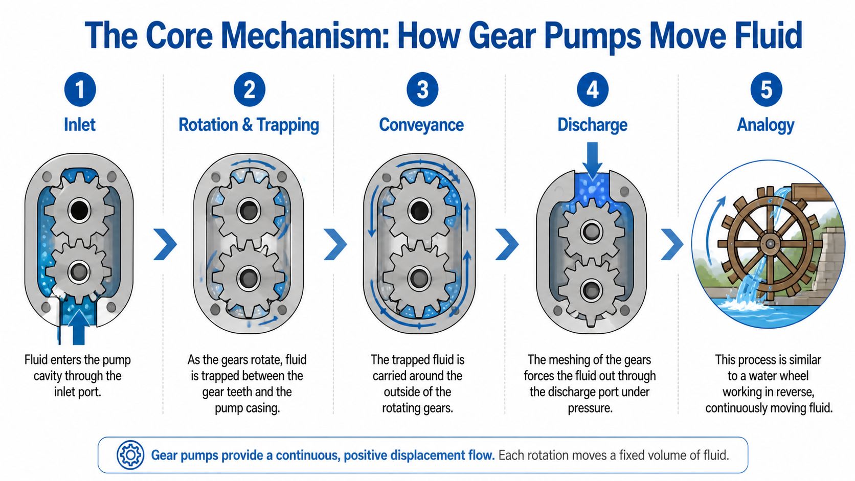
In a standard external gear pump, the drive gear turns the idler gear inside a closely fitted casing. As the teeth come out of mesh on the inlet side, the volume between the teeth opens up and local pressure drops. Oil then enters the pump because the pressure at the inlet line and reservoir is higher than the pressure inside those opening cavities.
The oil is carried around the outside diameter of the gears, trapped in the spaces between the tooth flanks and the housing bore. It does not travel through the meshing point in the centre. At the outlet side, the teeth mesh again, the trapped volume reduces, and the oil is forced into the pressure line.
That is the whole pumping action. The detail that matters in service is how well the pump maintains that trapped volume under real load, temperature, and contamination conditions.
The operating cycle in practical terms
-
Teeth separate at the inlet
The opening tooth spaces increase cavity volume and draw oil into the pump. -
Oil fills the tooth spaces
Each pocket of oil becomes part of the pump's fixed displacement for that revolution. -
Rotation carries the oil round the casing
The gears transport the fluid along the outside of the gearset. -
Teeth mesh at the outlet
The closing volume displaces the oil into the delivery port. -
System resistance determines pressure
The pump sends flow into the circuit. Pressure rises only when that flow meets resistance downstream.
On site, this is why a healthy pump can still leave an actuator underperforming if the problem sits elsewhere in the circuit. A relief valve held open, a spool leaking across lands, or a blocked suction strainer can all mimic pump trouble.
Why clearances decide real performance
Gear pumps depend on very small internal clearances between the gear faces, tooth tips, side plates and housing. Those gaps have to be tight enough to limit internal slip, but not so tight that the pump binds when the oil is cold or the casing grows with heat. That is one of the basic trade-offs in pump design. Better sealing improves volumetric efficiency, but the pump still needs to survive real operating temperatures and variable oil condition.
As noted earlier from Michael Smith Engineers, UK-supplied industrial gear pumps commonly work with inlet pressure limits, close radial and axial clearances, and volumetric efficiency figures that depend heavily on speed and pressure. In the field, the takeaway is straightforward. Once wear opens those clearances, more oil leaks internally from outlet back to inlet, and the first complaint is usually lost speed under load rather than a pump that stops turning altogether.
I see this regularly on mobile plant and older industrial power packs across the UK. The pump may look acceptable on the bench, but once the oil warms and the machine asks for pressure, internal leakage shows up quickly as drift, slow cycling, or weak steering response.
Good inlet conditions matter just as much. A gear pump cannot fill its tooth spaces properly if the suction line is restricted, air is entering through a loose fitting, or the oil is too viscous for the pipework and ambient temperature. That is why MA Hydraulics puts so much emphasis on application detail, not just flange pattern and displacement, when advising on replacements. If you want a reference for the other common layout, this overview of an internal gear pump design shows how the same displacement principle is packaged differently.
For a simple comparison outside hydraulic duty, even the Value Tools Co M18 pump still depends on the same fundamentals. It has to draw fluid in, trap it, and move it without losing too much back across its internal sealing points. Hydraulic gear pumps do that under far higher load, with much tighter tolerances and far less room for poor installation practice.
Good pump performance starts at the inlet. Poor suction pipework, air ingress, cold oil, and contamination will show up long before the gear teeth actually fail.
External vs Internal A Practical Comparison
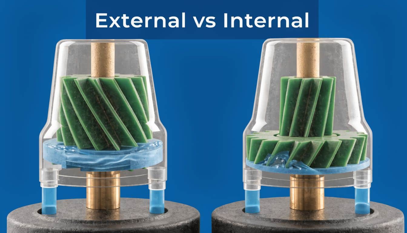
The two main layouts are external gear pumps and internal gear pumps, and the choice affects noise, contamination tolerance, replacement cost, and how forgiving the pump will be once it is out on site.
External gear pumps in working machinery
External gear pumps are the layout most technicians see on UK mobile plant, agricultural equipment, and standard industrial power packs. Two identical external gears mesh inside the housing, carry oil around the casing, and discharge it on the pressure side. The design is mechanically simple, compact, and usually the easier option to source and replace when downtime is expensive.
That matters in the practical world.
If a machine spends its life outdoors, gets serviced at uneven intervals, and needs to be back earning quickly, an external gear pump is often the safer choice. It will usually accept harsher service conditions better than an internal gear unit, even if it produces more pressure ripple and a more noticeable noise signature.
Typical uses include:
- Mobile machinery: loaders, compact plant, tipping circuits and steering systems
- Agricultural equipment: trailers, spreaders, log splitters and auxiliary functions
- General industrial duties: basic power packs and simple actuator circuits
Internal gear pumps in smoother-duty systems
Internal gear pumps use an eccentric inner rotor and outer gear with a crescent separator. That arrangement tends to produce smoother delivery and lower noise than a comparable external gear design, which is why these pumps are often specified on cleaner industrial systems, machine tools, and applications where flow quality matters as much as outright simplicity.
As noted earlier from Savree’s internal gear pump reference, internal gear units can run at high pressure, achieve good volumetric efficiency in the right operating range, tolerate some inlet vacuum, and suffer accelerated wear if particulate contamination is not controlled. Those points line up with what we see in practice. They can work very well, but they reward clean oil, stable suction conditions, and disciplined maintenance.
The trade-offs that matter on site
The usual mistake is to compare these pumps only on the catalogue sheet. In service, the better pump is the one that matches the machine’s working environment.
On a clean factory installation with decent filtration, controlled oil temperature, and regular servicing, an internal gear pump can give quieter operation and a more refined feel. On older mobile equipment with dirty reservoirs, cold starts, hose changes done in the field, and variable maintenance quality, an external gear pump usually holds up better and is easier to justify commercially.
Smoother and quieter does not automatically mean better. In poor operating conditions, contamination tolerance and replacement practicality often matter more than refinement.
A practical comparison looks like this:
| Pump type | Strengths | Compromises | Best fit |
|---|---|---|---|
| External gear | Simple build, durable in harsh service, easy to replace, good for general hydraulic duty | More noticeable pressure ripple and noise in some systems | Mobile plant, agriculture, straightforward industrial circuits |
| Internal gear | Smoother flow, lower noise, can cope better with difficult suction conditions when the system is clean | More sensitive to contamination and wear condition | Cleaner industrial systems, machine tools, selected power packs |
At MA Hydraulics, this is usually where selection decisions become straightforward. If the priority is a dependable replacement for a machine that has to work outside and be repaired quickly, external gear is commonly the right answer. If the system is well maintained, runs indoors, and the application benefits from quieter, steadier delivery, internal gear can be the better engineering choice.
Understanding Key Performance Characteristics
A pump data sheet only becomes useful when you can translate it into machine behaviour. Four characteristics matter most in practice: flow, pressure, efficiency and pulsation.

Flow and displacement
Flow starts with displacement. A gear pump moves a fixed volume every revolution, often expressed in cc/rev, and that tells you the theoretical output at a given shaft speed. Increase speed and you increase theoretical flow.
Actual flow is always lower than theoretical flow because some oil slips internally. That’s why a machine can feel weaker at working temperature than it did on a cold start. Warm oil usually leaks past worn internal surfaces more easily.
Pressure comes from resistance
Pressure is often misunderstood. The pump creates flow. The circuit creates pressure when that flow meets resistance from a load or a restriction such as a valve setting. If the system has an open path back to tank, the pump will still turn and move oil, but pressure won’t rise in any useful way.
That distinction matters during fault-finding. Low pressure doesn’t always mean a failed pump. It may mean the relief valve is passing, the actuator is bypassing internally, or the oil is taking the easiest route elsewhere.
Efficiency and what it tells you
Two forms of efficiency matter in practice.
- Volumetric efficiency relates to how much of the theoretical flow the pump delivers.
- Mechanical efficiency reflects losses from friction and internal drag.
When either drops, the machine pays for it in lost output, heat or extra input power. You don’t need a spreadsheet to spot the effect. Slow cycle times, poor lift performance and rising oil temperature usually tell the story first.
A short visual explanation can help if you’re training a fitter or apprentice on the basics:
Pulsation and why operators notice it
No gear pump delivers perfectly smooth, ripple-free flow. The geometry of the pumping chambers creates some level of pulsation as fluid pockets move from inlet to outlet. The operator may notice that as vibration, line noise or a slightly harsher actuator feel.
Internal gear pumps are often chosen where that matters more. External gear pumps remain widely accepted where ruggedness and simplicity carry more weight than acoustic refinement.
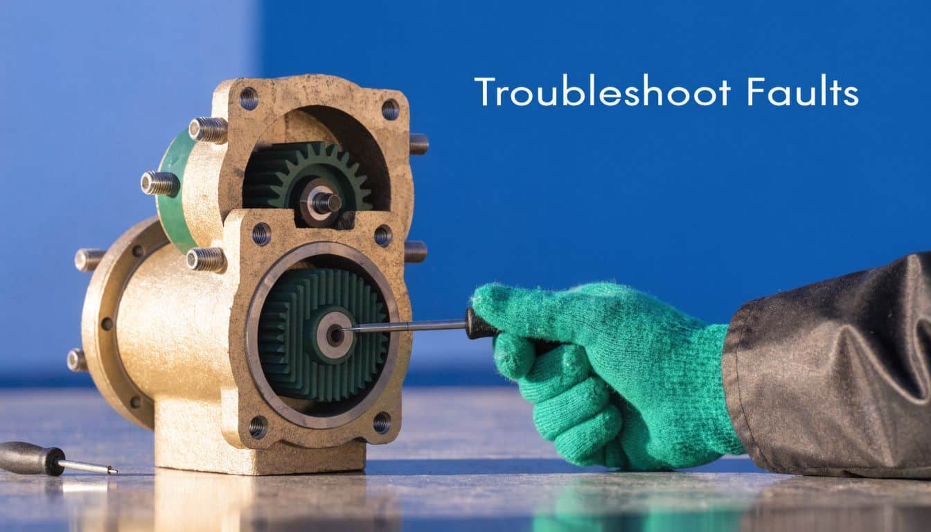
Common Faults and Troubleshooting in the Field
A gear pump in the early stages of failure rarely stops a machine outright. More often, the operator reports that steering feels heavier in the morning, a tipper slows under load, or a power pack starts sounding harsher by the end of the shift. Those are the jobs worth catching early, because the first symptom is usually cheaper than the repair that follows if the machine stays in service.
Low flow or weak pressure
Slow movement or poor lifting force does not prove the pump is finished. In field work across mobile plant, agriculture and industrial hydraulics, the fault is often elsewhere in the circuit.
Start with the simple checks that change the diagnosis fast:
- Confirm pump rotation: Wrong rotation after installation or motor rewiring causes immediate loss of performance.
- Check the inlet line: Blocked strainers, cracked suction lines, flattened hoses and low tank level all reduce inlet supply.
- Assess pump wear under load: A worn pump may look acceptable at idle but lose flow badly once pressure rises.
- Check the rest of the system for bypass: Relief valves stuck partly open, worn cylinders and hydraulic motors with internal leakage can all mimic pump failure.
Wear matters because gear pumps rely on controlled internal clearances. Once those surfaces wear, oil slips back internally instead of going to the actuator. The machine then feels weak, slow or inconsistent, especially when the oil is hot. In practice, trend matters more than any single strip-down measurement. If pressure and cycle speed have both been drifting for weeks, the pump and the rest of the circuit need checking as a system, not as isolated parts.
Noise tells you a lot
Sound is one of the best early indicators.
Cavitation usually has a sharper whine and points to poor inlet conditions. Aeration tends to sound rougher, with a rattling or crackling note because air is circulating with the oil. Both will damage internal surfaces quickly if the machine keeps running, and both are common after hose work, tank repairs, or filter changes where a small suction-side fault has been introduced.
If a pump gets noisy straight after service work, inspect the suction side before blaming the unit itself. Check every joint, hose condition, strainer, oil level and fluid condition.
Leaks and seal problems
A leaking pump is not always a failed pump, but repeated leakage is rarely just bad luck. Shaft seals, body seals and port joints usually fail for a reason.
Common causes include worn shafts, poor coupling alignment, excessive vibration, blocked case drainage where applicable, or pressure spikes that the pump has been seeing for some time. Replacing the seal alone may stop the leak for a few days, but it does not fix the root cause. In workshop practice, that is how simple oil leaks turn into repeat call-outs. If the unit needs proper assessment, specialist hydraulic pump repair support is often faster and cheaper than fitting parts by trial and error.
Overheating under duty
Heat is usually a symptom of inefficiency somewhere in the circuit. The pump may be part of it, but rarely all of it.
Check oil grade against the duty, verify reservoir level, confirm relief settings, and compare machine behaviour cold versus hot. A pump with internal wear often performs acceptably at start-up, then fades as the oil warms and leakage increases. On UK site equipment, that pattern shows up regularly on machines that have been run with marginal filtration or long oil change intervals.
A practical fault-finding order works well here. Check oil level first. Then inspect the inlet side, take temperature readings on the pump body and key lines, verify pressure settings, and watch actuator performance under no-load and working load. That sequence usually gets to the cause faster than replacing components one by one.
Selecting the Right Gear Pump for Your Application
Pump selection goes wrong when buyers focus on mounting and shaft details first and duty second. The right pump starts with the job the machine has to do, the fluid it uses, how clean the system stays and what the operator will tolerate.
A compact power pack for indoor production machinery has different priorities from a trailer-mounted agricultural unit. One may value smoother running and lower noise. The other may need rugged serviceability and fast replacement more than anything else.
Gear Pump Selection Criteria External vs. Internal
| Selection Factor | External Gear Pump | Internal Gear Pump |
|---|---|---|
| Required flow delivery | Strong choice for straightforward fixed-displacement duties | Strong choice where smoother delivery is preferred |
| Pressure demand | Well suited to many general hydraulic systems | Suits higher-pressure industrial duties where the design fits |
| Noise sensitivity | Usually less refined acoustically | Often preferred when quieter running matters |
| Fluid condition | Better fit where service conditions are harsher | Better fit where filtration and cleanliness are tightly controlled |
| Viscosity handling | Good general-purpose option | Often chosen where fluid behaviour and smoothness are important |
| Mobile vs industrial use | Common in mobile, agricultural and utility equipment | Common in cleaner industrial installations |
| Maintenance approach | Simpler replacement path in many machines | Rewards disciplined filtration and condition monitoring |
| Budget and lifecycle priorities | Usually the practical choice for cost-conscious rugged duty | Often justified where refinement and application fit matter more |
Questions worth answering before you order
Use these as a real screening list, not a paperwork exercise:
- What flow does the actuator need? Match pump displacement and drive speed to the machine’s required movement.
- What pressure will the system see in normal operation? Don’t size only for relief setting. Size for the duty the pump will live with.
- How clean is the oil in real service? Workshop assumptions don’t count if the machine spends its life outside.
- How important is noise? Indoor industrial machinery often has tighter expectations than a field machine.
- What are the packaging constraints? Mounting, shaft, rotation and port orientation still matter, but only after duty is clear.
Matching the pump to the whole hydraulic package
A pump shouldn’t be selected in isolation. Reservoir arrangement, suction line layout, relief settings, valve choice and motor speed all shape how the pump behaves in service. If the system is being designed or reworked as a whole, reviewing the complete hydraulic power unit package usually prevents mismatches that later get blamed on the pump.
For a log splitter or simple tipping circuit, a durable external gear pump is often the sensible route. For an indoor industrial power pack where smoothness and lower noise count, an internal gear pump may justify its place. Good selection isn’t about choosing the “best” pump. It’s about choosing the one that best suits the actual duty.
Proactive Maintenance and Expert UK Support
Most gear pump life is decided by three things: oil cleanliness, inlet condition and heat control. If those are poor, even a well-specified pump won’t stay healthy for long. If they’re managed properly, pumps usually give predictable service and clearer fault patterns.
A practical maintenance routine should include regular checks on fluid condition, oil level, filter state, suction integrity and external leakage. Watch for subtle changes in sound and response, not just outright failure. Those signs usually show up before the machine stops.
For maintenance teams trying to stay ahead of breakdowns, a documented PM routine helps. If your site needs a better framework for planning inspections and service intervals, this guide to streamline CMMS planning is a useful reference for organising preventive work rather than reacting to emergency stoppages.
Clean oil is cheaper than pumps, downtime and call-outs. Most repeat failures trace back to contamination, poor suction conditions or heat that nobody addressed early enough.
The best results come from treating the pump as part of the system, not as a standalone spare. Fit the correct unit, maintain the fluid, protect the inlet side and investigate small symptoms early. That approach works far better than waiting for a total loss of pressure and replacing parts in a hurry.
If you need advice on selecting, replacing or repairing a gear pump, contact MA Hydraulics Ltd for practical UK support on components and hydraulic systems. Phone 01724 279508 today, or send us a message.
