

A tractor power pack comes back into the workshop with a collapsed filter element, a bypass valve stuck open and oil that looks clean enough to the naked eye. The machine owner wants the filter replaced immediately. The engineer still needs to ask why the base allowed the restriction, whether the bypass protected the housing, and where the contamination entered in the first place.
That is the difference between treating a hydraulic filter base as a mounting bracket and treating it as a working part of the hydraulic circuit. Porting, sealing, flow capacity, element compatibility, bypass behaviour and service access all affect whether the system protects its pump and valves or circulates damaging particles.
What a Hydraulic Filter Base Actually Does
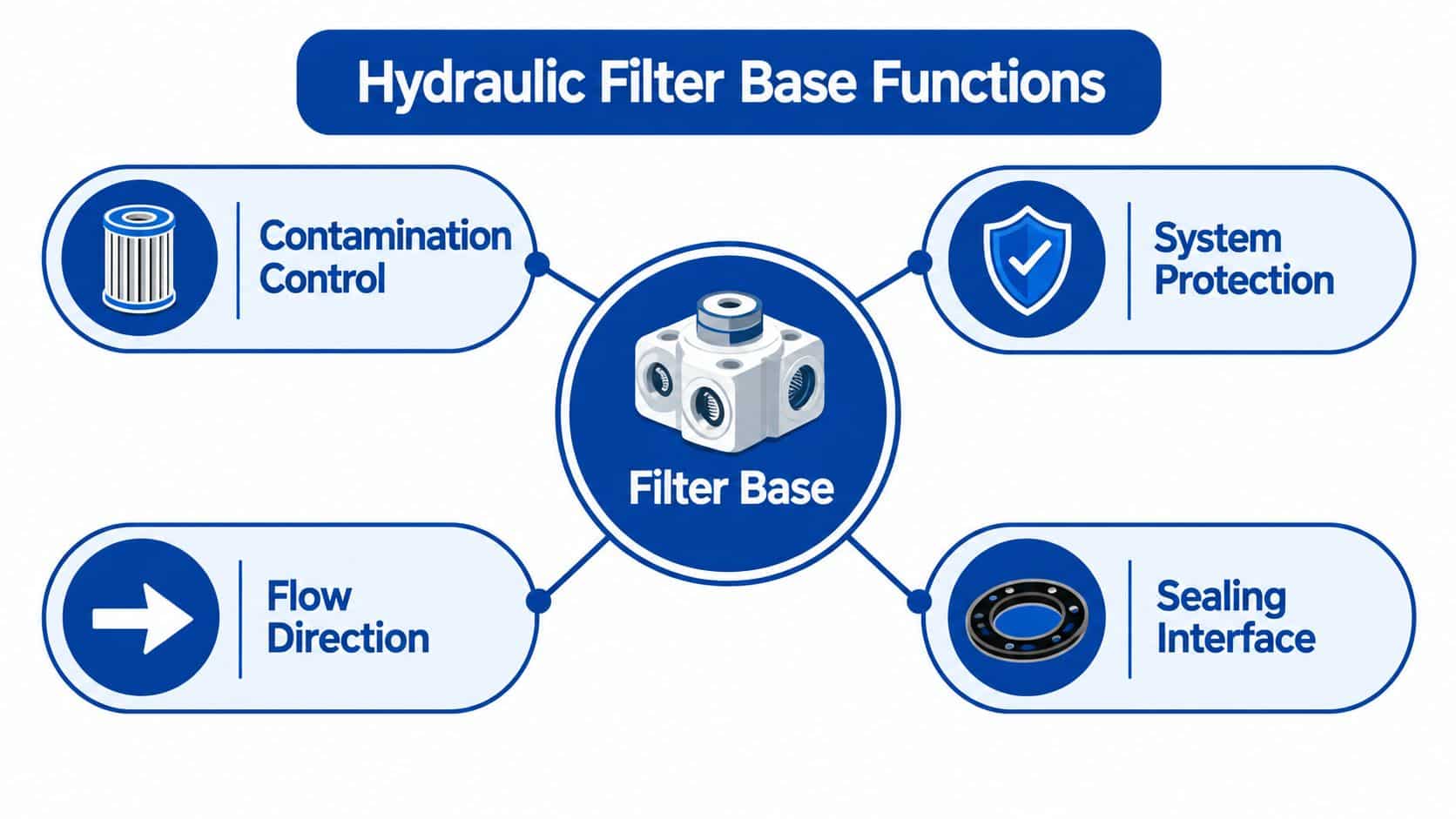
A hydraulic filter base performs three jobs at once. Mechanically, it supports the filter element or cartridge and connects the assembly to the machine. Hydraulically, it directs oil through the media while containing system pressure. From a maintenance perspective, it gives the engineer access to the element, differential-pressure indicator and bypass valve.
The base is the interface between contaminated oil and the part intended to remove that contamination. If the element is the wrong size, the seal is poorly seated or the flow direction is reversed, the filter may look correctly installed while doing very little useful work.
The mechanical interface
Start with the physical arrangement. The base must hold the element squarely, provide a reliable sealing face and withstand vibration, pressure pulses and temperature changes. On mobile plant, the mounting position also has to tolerate movement and make element replacement possible without removing adjacent pipework.
The port arrangement matters just as much. A base with the correct nominal thread can still be unsuitable if its port orientation creates a tight bend, places the indicator behind a guard or forces the installer to twist a hose into the wrong direction. Those faults often appear later as rubbing hoses, damaged seals or inaccessible servicing.
The hydraulic interface
Oil must enter the correct port, pass through the element and leave through the outlet without excessive restriction. The base also has to contain the pressure generated when the element loads with particles. Where a bypass valve is fitted, its setting must protect the housing and maintain flow without allowing unnecessary unfiltered circulation.
The UK history of contamination control explains why these details matter. A 1980 Department of Trade and Industry field survey attributed 55% of reported hydraulic-system problems to particles in hydraulic oil, as documented in the MP Filtri account of the DTI field survey. Later UK industry material reported that particle contamination accounted for up to 80% of hydraulic failures, while modern applications increasingly use 3-micrometre and 6-micrometre absolute filtration according to Castrol's industrial filtration report.
Practical rule: Specify the base and element as a matched assembly. A cheap head with an incompatible element isn't a filtration strategy.
The maintenance interface
A good base lets a technician see the indicator, isolate the circuit, remove the element cleanly and record what happened. HSE guidance recommends checking filters and strainers for blockage because rising differential pressure can open a bypass and return contaminated oil to the circuit. The HSE hydraulic machinery guidance also supports treating filtration as part of safe, controlled maintenance rather than a cosmetic housekeeping task.
The base should therefore be selected against flow, pressure, fluid temperature, element performance, bypass setting and cleanliness target. Port thread alone is not enough. A shortcut at the specification stage can become a failed pump, a sticking proportional valve or an avoidable machine stoppage.
Porting Standards and How They Shape the Base
Porting errors often appear during a replacement job, after the old base has already been removed. Two ports may accept the same hose size yet use different thread forms, sealing faces and installation rules. Treat the porting layout as part of the contamination-control interface, because a poor connection can admit air, shed debris or create a leak that bypasses the intended filtration path.
The four common families
BSP parallel thread is widely used on UK and European hydraulic equipment. The thread positions the fitting, but it normally does not provide the seal. Use the specified O-ring, bonded washer or face seal, and confirm that the fitting reaches the correct shoulder. Extra tightening will not compensate for a missing or damaged washer.
NPT taper thread is common on legacy and North American-supplied equipment. The male and female threads create the sealing action as they tighten, usually with a compatible thread sealant. Set the fitting orientation during installation. Backing it off afterwards can open a leak path.
SAE four-bolt flange connections suit higher-pressure circuits, vibration-prone machinery and larger flow paths where threaded ports become less attractive. The flange uses an O-ring face seal and clamping bolts. Tighten the bolts evenly and inspect the O-ring groove, since uneven loading can distort the seal.
CETOP and DIN patterns support modular valve and manifold arrangements. They reduce external pipework and suit compact power packs, but similar-looking footprints are not automatically interchangeable. Check the mounting pattern, port identification and specified face seal before fitting a replacement.
| Porting Standard | Sealing Method | Typical Pressure Range | Best Fit For |
|---|---|---|---|
| BSP parallel | O-ring or bonded washer | Must be confirmed from the base specification | UK and European power packs, mobile machinery |
| NPT taper | Thread interference with compatible sealant | Must be confirmed from the base specification | North American and legacy imported equipment |
| SAE four-bolt flange | O-ring face seal and bolted flange | Must be confirmed from the base specification | Higher-pressure or high-flow pipework |
| CETOP/DIN pattern | Defined face seal and mounting interface | Must be confirmed from the base specification | Modular valves and compact manifolds |
A retrofit check that prevents rework
Before ordering, record the thread standard, nominal size, port orientation, mounting-hole pattern, seal location and flow direction from the drawing and the old component. Confirm whether the assembly uses a parallel thread with a washer or a taper thread that seals within the port.
Thread size alone is an unreliable cross-reference. Check the element part number, housing working pressure, indicator position, bypass arrangement and mounting depth separately. Then verify the base against the machine's cold-start viscosity, intermittent peak flow and required ISO 4406 cleanliness target, rather than selecting it from nominal flow alone.
For a manifold-mounted installation, measure the available envelope and the clearance needed to withdraw the element. On hose-connected equipment, check bend radius and port direction. A poorly orientated connection can impose side-load on the fitting, disturb the seal and make service contamination more likely. (398 words)
Sealing Options and Pressure Ratings
A filter base can carry a high pressure rating and still leak because the sealing arrangement is wrong. The metal body contains the load, but the seal controls the oil path.
Match the seal to the fluid and temperature
NBR, or nitrile, is a practical choice for many mineral hydraulic oils and moderate operating conditions. It offers a sensible balance of cost and availability, which is why it remains common in agricultural machinery and general-purpose power packs.
FKM, often known by the trade name Viton, earns its extra cost when temperature, fluid compatibility or long exposure to hot oil makes nitrile marginal. A hot return-line base or equipment operating near a heat source may justify it, provided the complete seal specification supports the application.
EPDM can suit particular fluid families, but it isn't a universal substitute for NBR or FKM. Compatibility must be checked against the hydraulic fluid, additives and operating temperature before installation.
O-rings need the correct groove, hardness and, where pressure and clearance require it, a back-up ring. A seal that extrudes into a clearance gap can fail even when the housing and pressure rating appear adequate.
Compare the sealing interfaces
BSP parallel ports generally rely on an O-ring or bonded seal washer at the face. The thread positions the fitting, but the washer or O-ring does the sealing. Reusing a flattened bonded washer is false economy.
NPT fittings seal through the tapered thread and need a sealant compatible with the fluid and the fitting material. Excess sealant can enter the hydraulic circuit, while over-tightening can split a port or make future removal unnecessarily difficult.
SAE flange connections use an O-ring in a controlled face groove. The flange bolts need even tightening and the correct grade. A damaged groove, an old O-ring or uneven clamping can leak at pressures well below the stated housing capability.
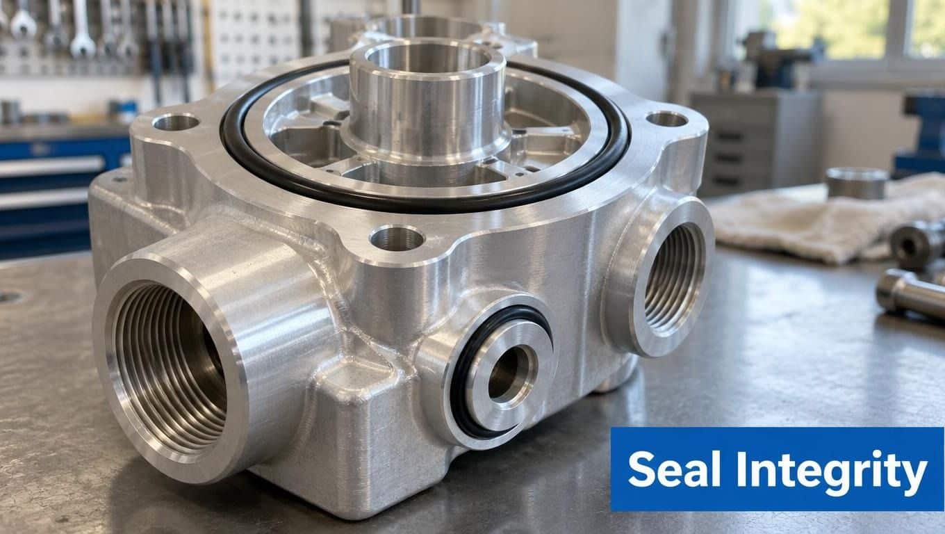
A base rated to 350 bar with an inferior seal is still a leaking base if the seal fails at 200 bar.
Read the pressure specification properly
Separate maximum working pressure, proof pressure and any stated fatigue or pressure-pulse limitation. Confirm the rating for the complete assembly, not just the aluminium or steel body. The indicator, bypass cartridge, element support and seals must all suit the same duty.
For a tank-mounted suction strainer base, a correctly specified nitrile seal is often the sensible choice where the fluid and temperature range are conventional. For a hot-return-line filter, FKM may be the better engineering decision. The right answer comes from fluid compatibility and temperature, not from choosing the most expensive seal.
Reading Flow Ratings and Bypass Behaviour
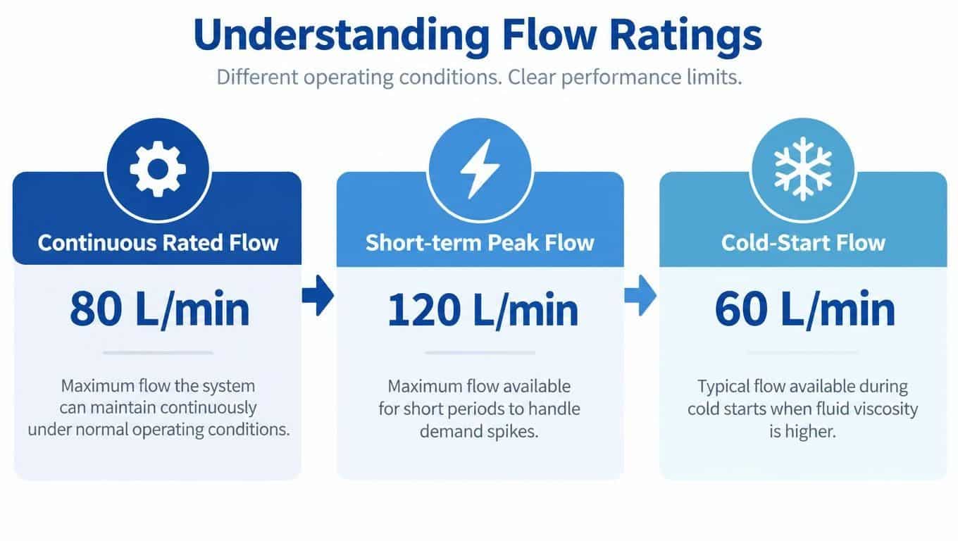
A headline flow figure doesn't tell you how a filter base will behave during a cold start. You need to separate continuous rated flow, short-term peak flow and the flow condition created by cold, viscous oil.
A base rated at 100 L/min at 30 cSt won't behave the same way at 200 cSt during a January start. The element and passages create greater differential pressure as viscosity rises. A machine that runs comfortably once warm may restrict heavily before the oil reaches normal temperature.
Use the operating envelope, not the catalogue headline
Continuous flow is the duty the base can carry repeatedly under the stated conditions. Short-term peak flow covers transient demand, such as actuator movement or an intermittent high-flow cycle. Cold-start flow needs separate attention because viscosity can make the clean element look heavily restricted.
Check the manufacturer's pressure-drop curves for the actual element, oil viscosity and temperature. If the catalogue only gives a nominal rating without test conditions, treat the figure as an initial reference rather than a final sizing decision.
The bypass valve is part of that calculation. A setting commonly encountered in hydraulic filter assemblies is around 2.5 to 3.5 bar differential, but the correct value depends on the element, housing, circuit and component protection requirement. The bypass mustn't open so readily that contaminated oil circulates during normal operation, and it mustn't stay closed while pressure threatens the housing or pump supply.
Indicators make the condition visible
A visual indicator is simple and useful if the technician can see it from the service position. An electrical switch can send an alarm to a control panel. An electronic sensor can support trend monitoring, but it still needs correct installation and interpretation.
A base without an accessible indicator makes maintenance guesswork. Cold oil may create a temporary restriction signal, while a failed indicator or open bypass may create no signal at all. Record differential pressure at a known temperature and flow, then compare like with like.
Element performance also needs evidence. BS ISO 16889:2022, the British implementation of ISO 16889, provides the multi-pass method used to evaluate filter performance and beta ratios under controlled contaminant loading, as outlined in this UK hydraulic filter selection guidance. A base can't compensate for an element that lacks suitable verified performance.
Integrating the Base with Manifolds and Cartridges
The filter base sits within a system, not in isolation. On a typical UK power pack, it may connect the pump outlet to a valve manifold, sit in the return line before the reservoir or form part of a tank-top assembly.
An in-line base gives flexibility in pipe routing and is useful where the filter needs to be positioned away from the tank. It also adds pipework and connection points, so the installer must control hose movement, support and access.
A manifold-mounted base keeps the circuit compact and can reduce external plumbing. The trade-off is that a poor layout can hide the indicator or leave too little room to remove the element. Measure service clearance before committing to the manifold pattern.
A tank-top or in-tank base can simplify reservoir integration and protect oil before it returns to the tank. It needs careful attention to tank access, cover sealing, internal clearances and contamination introduced during servicing.
Match the cartridge family
Spin-on canisters are convenient for straightforward replacement, but the head geometry, thread and gasket arrangement must match the cartridge. Disposable in-line elements may offer a different service method and can be better suited to a defined housing with a replaceable internal element.
Don't assume that two cartridges are compatible because their outside dimensions are similar. Confirm the sealing face, locating feature, bypass arrangement, collapse resistance and flow direction. A filter head that accepts the wrong element can allow internal bypass or fail to seal at the centre tube.
Design for the delivered assembly
When a supplier assembles a Hydronit mini power pack or builds a bespoke industrial power pack, the base affects the manifold envelope, pipework route, service points and final testing. In-house power-pack work up to 11 kW is described by the MA Hydraulics bespoke power-pack service, but the same design logic applies to any UK-built assembly.
The useful comparison is not which cartridge costs less. It is which arrangement gives reliable contamination control, clear service access, manageable replacement and a sound pressure-drop margin throughout the machine's duty cycle. For organisations also maintaining commercial vehicles or workshop equipment, browse Brothers Truck Trailer repair services for a wider example of how service access influences practical equipment support.
Installation, Commissioning and Service Intervals
Install the filter base with the first service visit in mind. It is a contamination-control interface, not just a mounting bracket. Choose a position where the flow arrow and indicator are visible, the element can be removed cleanly, and the base does not sit in a pocket where dirt collects.
Install it deliberately
-
Confirm the flow direction. Compare the arrow on the base with the circuit drawing. A reversed element can increase restriction or leave the oil poorly filtered.
-
Confirm the connection standard. Check BSP, NPT, flange or manifold pattern before fitting pipework. Use the specified O-ring, bonded washer or face seal. Thread sealant is not a substitute for the correct sealing method.
-
Inspect the mounting surface. Remove dirt and old seal material without damaging the machined face. Check that the element support, centre tube and bypass components are seated correctly.
-
Tighten to the manufacturer's figures. Extra force will not correct a missing or damaged seal. Support hoses and pipes so their weight and vibration are not transferred into the base.
-
Position the indicator for inspection. An indicator hidden behind pipework cannot support condition-based maintenance. Leave enough clearance to remove the element without disturbing adjacent components.
Follow the relevant hydraulic installation guidelines alongside the base manufacturer's instructions.
Commission before trusting the machine
Fill new or transferred oil through a suitable fine filter. Do not pour it from an open container into the reservoir. Establish a particle-count baseline against the target ISO 4406 cleanliness code. ISO 4406 reports particle populations greater than 4, 6 and 14 µm(c), making the result more useful than judging oil by appearance, as explained in the HSE filtration guidance.
Size and assess the base under real operating conditions. Cold-start viscosity can create a high initial pressure drop, while intermittent peak flow can overload a base selected against nominal flow alone. Run the system at a known temperature and flow, then record clean differential pressure. Take both cold and warm readings, noting the conditions with each result. This gives the service team a reference for the machine's cleanliness target and normal bypass margin.
Set a service record
UK-oriented maintenance guidance commonly recommends an initial element change after roughly 50 operating hours, followed by approximately 250 to 500 operating hours or six months, adjusted for duty and contamination history, as summarised in this UK hydraulic filter cross-reference guidance.
Record:
- Machine and circuit: Asset identity, filter location and application.
- Element details: Part number, rating, seal material and batch information.
- Operating conditions: Hours, oil temperature, observed flow and differential pressure.
- Inspection result: Element condition, bypass status, seal condition and visible debris.
- Oil condition: Sample date, ISO 4406 result and action taken.
Before replacing an element, isolate and lock off the machine, release stored pressure and verify zero energy. HSE identifies high-pressure fluid injection as a serious hazard. Its fluid-injection safety guidance supports clear pressure-release procedures. Use equipment maintenance tags from Evright Industrial to identify isolation points and maintenance status clearly.
Diagnosing a Filter Base That Is Not Behaving
An indicator that hasn't tripped doesn't prove the filter is healthy. A low differential pressure can mean clean oil, but it can also indicate an incorrectly seated element, an open bypass, a failed indicator or insufficient flow through the element.
Start at the physical basics. Verify flow direction, inspect the sealing faces and confirm that the element is the correct part. Then test the bypass valve and indicator rather than assuming either one works because the assembly looks intact.
Compare differential pressure with cold oil and warm oil under comparable flow conditions. High pressure with a new element can point to the wrong rating, an undersized base, surge flow or unusually viscous oil. Low pressure with poor cleanliness can point towards bypassing or contamination entering elsewhere.
Take an oil sample and obtain an ISO 4406 particle count. Check breathers, tank lids, inspection covers, hose connections, top-up containers and cleaning practices. Wear debris can also indicate that the filter is reporting a symptom rather than causing the failure.
A machine that's down needs evidence, not another filter fitted by guesswork.
The MRO engineer's decision is whether the base is the fault, the bypass is the fault or the contamination source sits somewhere else in the circuit. A Scunthorpe-based hydraulic specialist can help with cross-references, filter-base selection, diagnostics and complete power-pack requirements.
MA Hydraulics Ltd supplies hydraulic filter bases, filter housings, valves, pumps and complete power solutions for agricultural, mobile and industrial equipment. Visit MA Hydraulics Ltd for component selection support, bespoke power-pack advice and UK technical assistance, or phone 01724 279508 today, or send a message with your application details.
