
You're standing beside a tractor or conveyor, watching the prime mover turn briskly while the implement or drive needs something very different. The pump may need a controlled rotational speed, the conveyor may need more turning force, and the available engine speed may not suit either job directly. A gearbox sits between those components and makes the match possible.
That's the practical answer to how do gearboxes work. They transmit rotary power while changing speed and torque to suit the machine. The same basic principle appears in a tractor PTO, a materials-handling drive, a hydraulic power pack and industrial machinery. The details vary, but the trade-off remains: lower speed normally means higher torque, while every real gearbox introduces some friction, heat and power loss.
This guide starts with meshed gears and simple ratios, then moves through common gear types, PTO and reduction gearbox layouts, hydraulic applications, efficiency and maintenance. By the end, you should be able to look at a gearbox specification and ask the useful workshop questions: what speed enters, what speed must leave, how much torque is required, how much heat will be produced, and what maintenance will keep the unit reliable?
For OEMs, operators and MRO teams, those questions matter more than identifying whether a gearbox is manual or automatic. A correctly selected unit protects pumps, motors, bearings and couplings. A poorly matched unit can waste input power, run hot and shorten service life, even when the machine appears to operate normally.
Introduction to How Gearboxes Work in Everyday Machinery
A gearbox is a mechanical power-transmission device. Its job isn't to “change gears” in the passenger-car sense. In industrial and mobile equipment, it often provides a fixed speed reduction, connects a prime mover to a hydraulic pump, changes the direction of rotation or makes a compact drive arrangement possible.
Take a tractor supplying an auxiliary hydraulic circuit. The engine may turn faster than the pump should run. Connecting the pump directly could overspeed it, create excessive flow or impose an unsuitable load on the shaft. A PTO gearbox adapts the engine's rotary output so the pump receives a usable speed and torque combination.
A similar problem appears on a factory conveyor. The motor may rotate too quickly for the belt or roller, but the conveyor needs substantial turning force to start and move a heavy load. A reduction gearbox slows the output and increases available torque, subject to the losses inside the gear train.
Workshop rule: Never select a gearbox from speed alone. Match the ratio, torque, duty cycle, mounting arrangement, lubrication and thermal conditions to the complete machine.
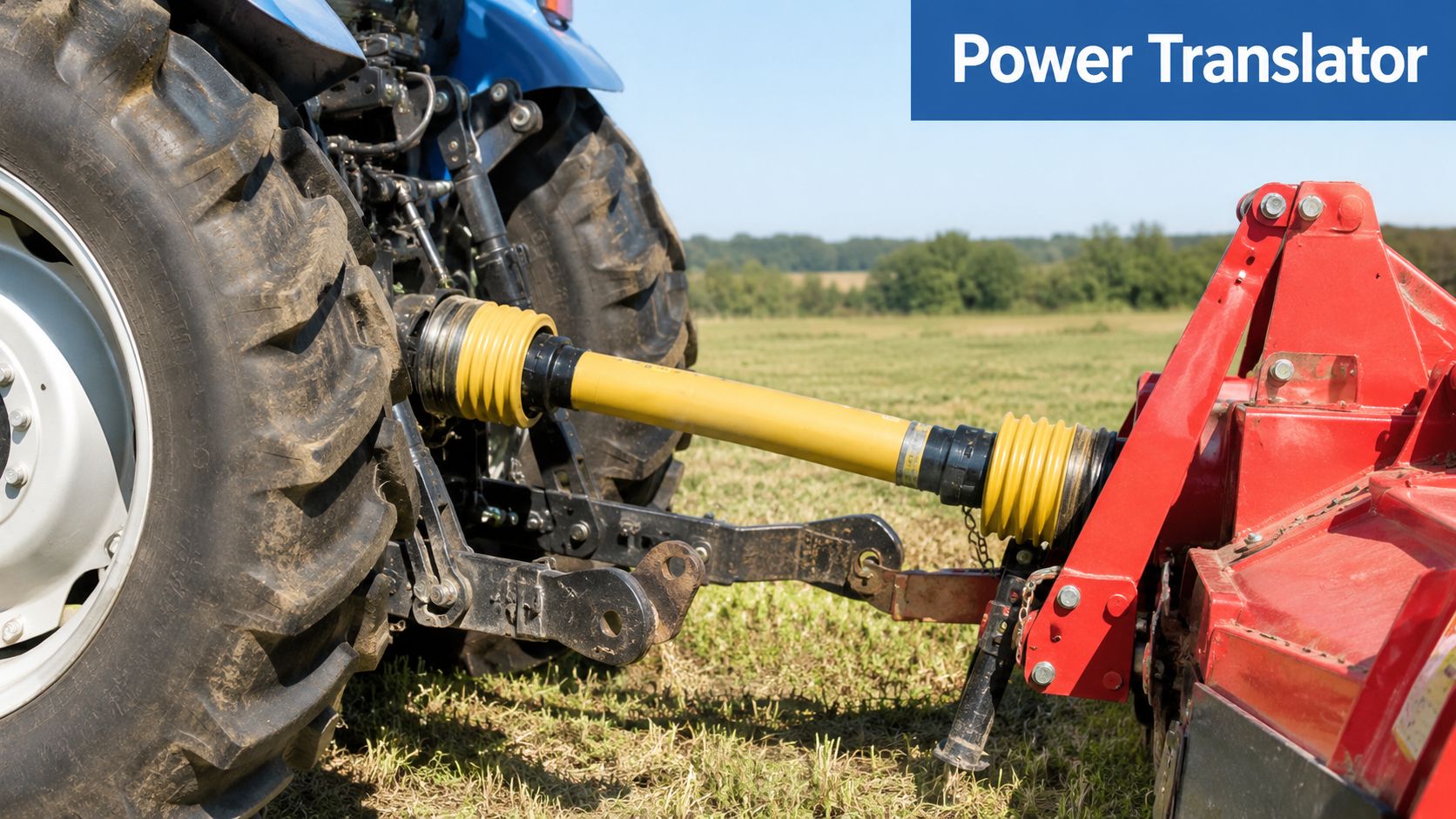
The gearbox is therefore a translator between the prime mover and the working component. It translates high-speed, lower-torque rotation into slower, higher-torque rotation, or it may provide a different arrangement where space, direction and connection requirements dictate the design.
This matters in UK machinery because agricultural equipment, mobile plant and industrial drives often work in changing conditions. Cold starts, dust, moisture, heavy loads and restricted cooling can all affect how a gearbox behaves. A unit that appears adequate on a drawing may become unsuitable if the application runs continuously, starts under load or places extra heat inside a compact enclosure.
The learning path is straightforward:
- Start with the teeth: Understand how two gears transfer rotary motion.
- Follow the ratio: See why tooth count changes speed and torque.
- Compare designs: Learn where spur, helical, planetary and worm gears fit.
- Apply the principle: Connect PTO and reduction gearboxes to pumps, motors and conveyors.
- Protect the investment: Use efficiency, temperature and maintenance checks when specifying equipment.
The important shift in thinking is this: a gearbox isn't only a mechanical speed changer. It's also an energy, cooling and reliability decision.
The Core Principles Behind Gearbox Operation
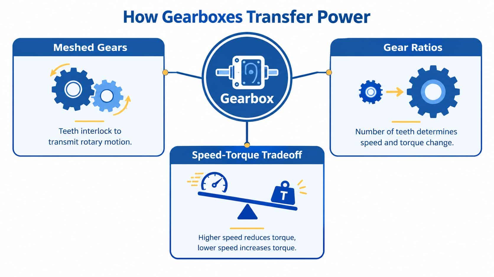
A gearbox starts with a simple interaction: two toothed wheels mesh, and one drives the other. As the smaller driving gear turns, its teeth push the larger driven gear. The output gear rotates in the opposite direction, carrying rotary motion from the input shaft to the output shaft.
Tooth count sets the ratio. If the driven gear has twice as many teeth as the pinion, it turns at half the speed and receives about twice the torque, as explained in Britannica's explanation of basic gear operation. The larger gear takes longer to complete each revolution, but the contact force acts farther from the output shaft centre, increasing its turning effect.
A bicycle shows the same trade-off. A small front chainring driving a larger rear sprocket gives the rear wheel more turning force at lower speed. A larger front chainring and smaller rear sprocket make the wheel turn faster, although the rider must apply more effort. A gearbox uses meshed gears instead of a chain and sprocket, but the principle remains the same.
Ratio and rotational speed
For a simple reduction gearbox, use:
Output speed = input speed ÷ reduction ratio
With a prime mover running at 1500 rpm and a 3.00:1 reduction ratio, the output shaft runs at 500 rpm. Three input revolutions produce one output revolution. The same relationship appears in IPE's gearbox explanation.
The ratio does not create extra power. It exchanges speed for torque. In a hydraulic installation, that exchange can let a pump or motor operate at a more suitable shaft speed, while the reduced speed supplies greater turning force at the output. Friction, seal drag and bearing losses mean the output power is lower than the input power.
Why torque rises as speed falls
Torque is the twisting force available at a shaft. A spanner shows the idea clearly: a longer handle gives the applied force more distance from the fastener, so the turning effect increases. A reduction gear produces a similar result by using a smaller input gear to drive a larger output gear.
A reduction ratio above 1:1 lowers rotational speed and raises output torque in proportion to that ratio, subject to efficiency losses. Groschopp's guide to gear reduction explains this relationship.
The output still has a working limit. Teeth, shafts, bearings, keyways and couplings must carry the transmitted load. Starting under load, shock loading and reversing can impose forces well above those seen during steady running. In hydraulic machinery, the selected gearbox must also cope with the pump or motor duty cycle, heat generation and available cooling space.
Several gear pairs can be combined to obtain a larger overall reduction. Multiply the individual stage ratios to find the total ratio. Each extra stage adds gear contact, bearing and seal losses, so the designer balances torque, efficiency, noise, heat and physical size. That balance affects energy use and cooling requirements in mobile and industrial hydraulic systems.
Gearbox selection also affects the space a machine occupies. For readers planning equipment layouts, this rack layout for aerospace manufacturing shows how machinery footprint can shape the surrounding floor plan.
Understanding Gear Types and How They Shape Performance
Gear type affects how a gearbox handles load, speed, noise, heat and ratio. The right choice depends on the hydraulic or industrial duty, available space and the energy lost during operation.
| Gear Type | Typical Efficiency | Key Strength | Limitation |
|---|---|---|---|
| Spur | 98–99% in common UK engineering guidance | Simple, efficient and cost-effective | Tooth engagement can produce more noise and impact |
| Helical | 98–99% in common UK engineering guidance | Smooth, quiet load transfer | Produces axial thrust and needs suitable bearing support |
| Planetary | About 94% for a two-stage example | High torque density and compact packaging | More complex construction and servicing |
| Worm | Can be as low as 20% under poor conditions | High reduction in a compact arrangement | Sliding contact creates heat and lower efficiency |
The figures in the table are examples rather than guarantees for every gearbox. The technical gearbox reference shows how two-stage spur and planetary arrangements can differ. Lubrication, load, speed, alignment, temperature and manufacturing quality all affect the result.
Spur and helical gears
Spur gears have straight teeth running parallel to the shaft. They are simple to manufacture and can transmit power efficiently. Their teeth engage more abruptly, however, which can increase noise and vibration at higher rotational speed or where backlash is present.
Helical gears use angled teeth, so contact builds progressively across the tooth face. The drive is usually smoother and quieter. The angled contact also creates axial force, meaning the housing and bearings must support that additional load.
Both types can suit applications where energy efficiency and continuous power transmission matter. In a hydraulic drive, that affects more than the quoted efficiency. Lost power becomes heat, so the gearbox and its oil may require enough surface area, airflow or cooling capacity to maintain a safe working temperature.
Planetary and worm gears
A planetary gearbox has a central sun gear, planet gears and an outer ring gear. Several teeth share the load, giving the arrangement high torque capacity in a compact package. It suits equipment with restricted installation space or a high torque-to-size requirement. Examples are shown by planetary gear boxes from Intech.
Worm gears use a screw-like worm to drive a wheel. Sliding contact allows a high reduction in a compact assembly, but it produces more friction and heat than a mainly rolling gear mesh. That can suit intermittent operation, limited space or a particular holding requirement. Continuous hydraulic duty needs careful checks on lubrication, heat removal and the permitted operating load.
The smallest gearbox may not cost the least to run. Compare purchase price with input power, cooling requirements, running hours and maintenance access before selecting the gear type and ratio. A slightly larger, more efficient arrangement can reduce heat and energy use across a machine's working life.
How PTO and Reduction Gearboxes Work in Practice
A tractor working a hydraulic pump shows why gearbox choice matters. The engine supplies rotary power, but the pump needs a particular shaft speed, torque and mounting arrangement. A PTO gearbox and a reduction gearbox use related gear principles, yet they adapt power for different jobs.
A PTO gearbox takes rotary power from an engine or tractor PTO and transfers it to an auxiliary component, often a hydraulic pump. It can alter speed, provide a suitable mounting interface and align the pump shaft with the driven shaft. Bellhousings and couplings connect the components, maintain alignment and shield the rotating assembly.
A reduction gearbox accepts power from a motor, engine or another prime mover, then delivers slower rotation to a drive. The lower output speed gives the working shaft more torque for applications such as conveyors, agricultural machinery and mobile equipment. The guide to reduction gearboxes explains this mechanical arrangement in further application context.
A PTO example
Assume a tractor drives a PTO gearbox connected to a gear pump. The engineer checks the available input speed, the pump's permitted speed range, the required hydraulic flow and the pressure duty. The selected ratio then sets the shaft speed reaching the pump.
With the wrong ratio, the hydraulic system pays the price. Excessive pump speed can increase noise, oil temperature and wear. Too little speed can leave the circuit short of the flow it needs. The gearbox therefore affects usable hydraulic output, energy loss and cooling requirements, not just shaft rotation.
Correct sizing also depends on the connection. The bellhousing must suit the pump and prime mover, while the coupling must transmit the required torque. Shaft alignment matters because even a small error can increase bearing and seal loading.
A reduction example
With a 1500 rpm input and a 3.00:1 ratio, the output speed is 500 rpm, using the ratio formula set out earlier. The reduction increases available output torque, although friction and other losses reduce the power delivered at the output shaft.
Select the assembly by checking:
- Input conditions: Record speed, direction, prime mover and starting behaviour.
- Output demand: Establish required speed, torque and duty cycle.
- Interface: Confirm shaft dimensions, flange pattern, bellhousing and coupling.
- Environment: Consider dust, water, ambient temperature and available cooling.
- Service plan: Check oil access, inspection points and replacement availability.
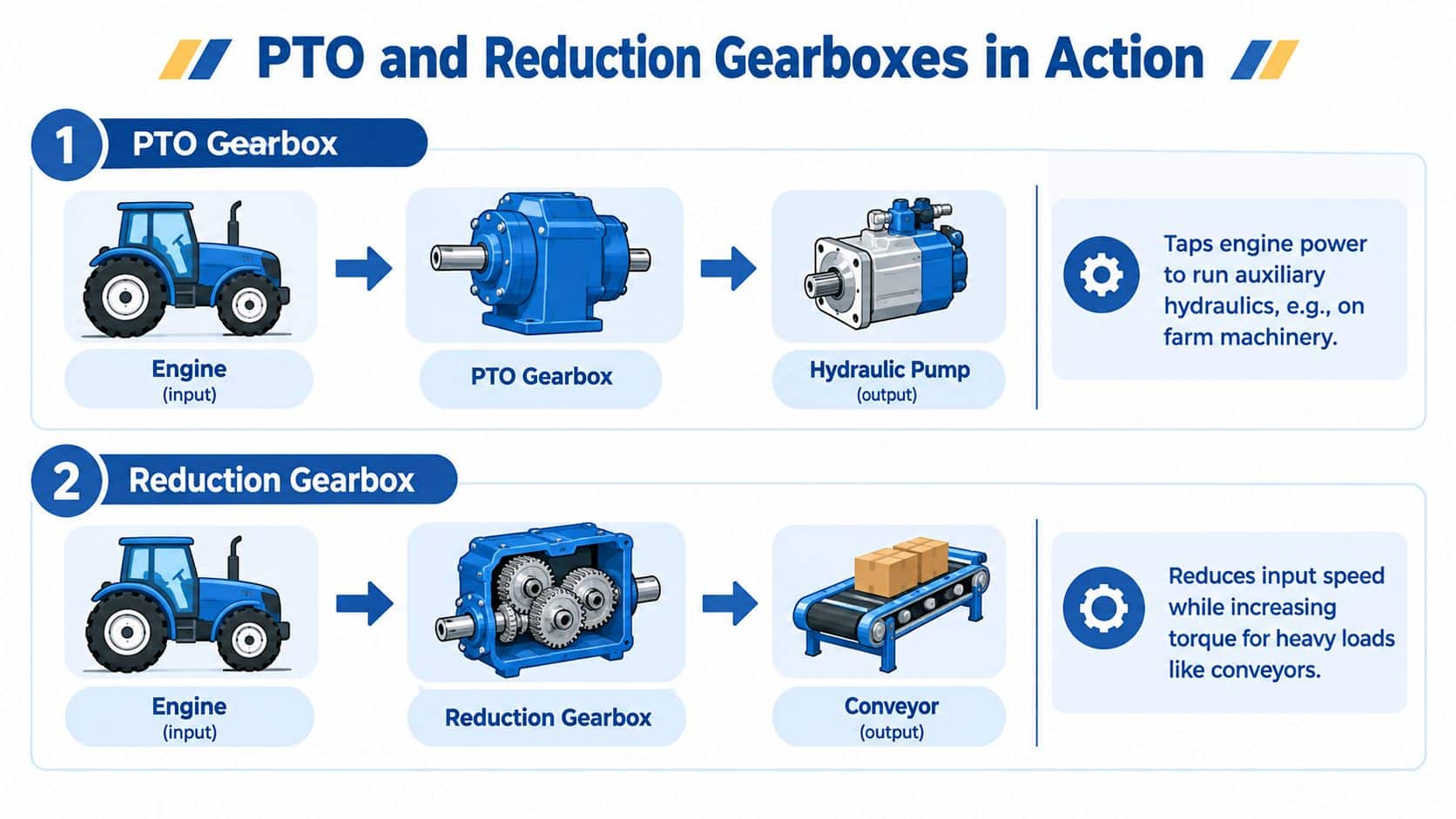
The same power path may drive a gear pump, hydraulic motor or conveyor shaft. Assess the gearbox, coupling, shafts and driven equipment together, because a mismatch at one point can create heat, vibration or lost hydraulic performance elsewhere.
Where Gearboxes Are Used in Mobile and Industrial Hydraulics
Gearboxes add value wherever the prime mover and the hydraulic or mechanical load operate at different speeds or torque levels. The application might be a tractor powering a sprayer, a telehandler lifting a pallet, a conveyor moving materials or a factory press repeating a controlled movement.
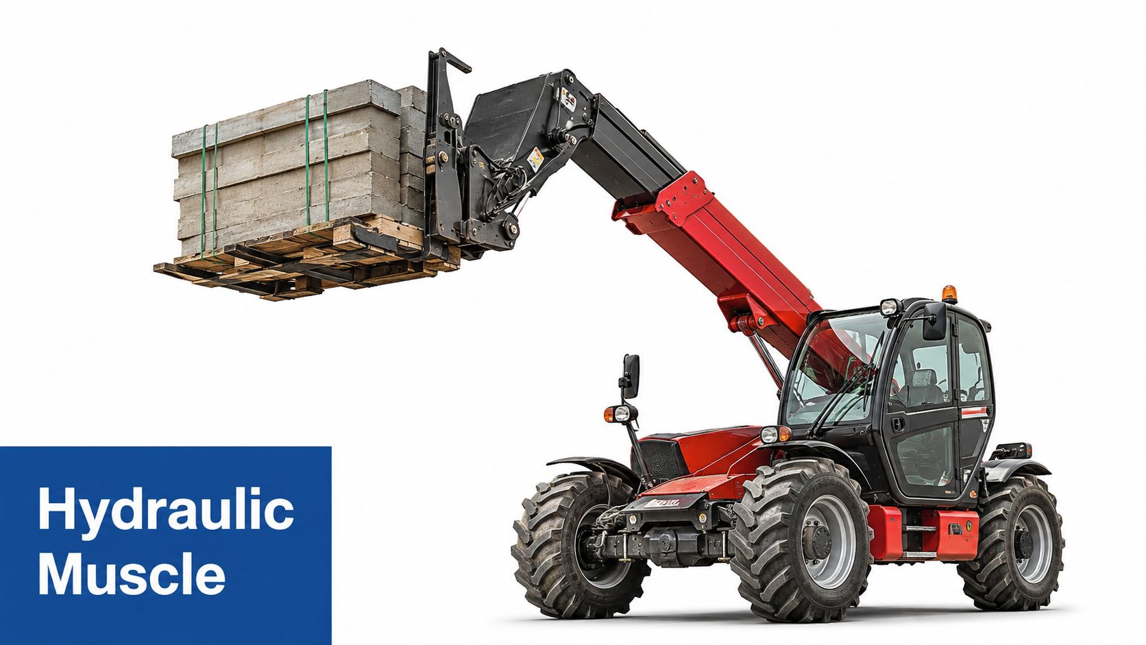
A telehandler is a good example of several systems working together. The engine provides the primary rotary power, the gearbox adapts that power for the hydraulic pump, and the hydraulic circuit controls boom, attachment and steering functions. The engineer must consider available flow, working pressure, shaft speed, pump displacement and the way the machine starts and changes load.
Agriculture and mobile plant
Agricultural PTO gearboxes often work in dirty, variable conditions. A tractor may operate an auxiliary pump for a tipping trailer, sprayer, loader or other implement. Shock loads can occur when an implement starts, stalls or encounters changing ground conditions, so the gearbox and coupling need sufficient mechanical margin.
The hydraulic side also needs the right pump and motor combination. A gear motor for hydraulic applications converts hydraulic flow and pressure back into rotary output, making it useful for fans, augers, winches and other mobile mechanisms.
Industrial power packs
An industrial machine may use a gearbox to connect an electric motor to a hydraulic pump when the motor speed and pump requirements don't match. MA Hydraulics Ltd supplies hydraulic components, PTO and reduction gearboxes, and bespoke industrial power packs up to 11 kW, helping customers combine components for mobile and industrial systems.
The practical design work includes checking the pump group, displacement, pressure, flow, motor speed and mounting arrangement. Gear pumps in Groups 0 to 3 may suit different flow and packaging requirements, while Hydronit mini power packs can be assembled to specified customer requirements.
Manufacturing and materials handling
A factory press may need steady hydraulic power and repeatable operation. A conveyor may need high starting torque and controlled output speed. In both cases, the gearbox affects the load seen by the motor, the temperature inside the enclosure and the torque delivered to the working component.
The correct choice depends on the machine's actual duty, not only its peak rating. Continuous running, frequent starts, reversing, shock loading and restricted ventilation can all change the selection.
Efficiency Heat and Why Gearbox Choice Affects Running Costs
On a mobile hydraulic machine, a gearbox may run for hours beside a pump, motor or working attachment. Even a small efficiency loss becomes heat that the oil and housing must carry away. Efficiency is the ratio of output shaft power to input shaft power. At 95% efficiency, a gearbox delivers 95% of its input power as useful output and converts the remaining 5% into heat.
For example, a gearbox receiving 5 kW at that efficiency loses 250 W as heat. That energy warms the lubricant, bearings, housing and surrounding enclosure. If the machine cannot dissipate it, temperature rises, which can shorten lubricant life, reduce seal performance and increase bearing wear.
The gear type changes the thermal burden
The figures in the gear-types table, as tabulated earlier, show why internal arrangement matters. Spur, helical, worm and planetary designs do not create the same friction under the same duty. Tooth contact, sliding, rolling, the number of stages, speed and load all affect the power that becomes heat.
Worm gearing usually creates more sliding contact between the worm and wheel than spur or helical gearing. That can increase heat, particularly where lubrication, alignment or loading is unsuitable. A compact high-ratio gearbox may therefore need more cooling than its size suggests.
Operating conditions can shift the result further. Correct oil, accurate alignment, suitable loading and the intended speed help the gearbox work near its design performance. Poor oil condition, overload, restricted ventilation or frequent starts increase friction and thermal stress.
Calculate the loss before choosing the compact option
A smaller housing or higher ratio may simplify installation, but it can raise the energy used during the machine's working life. The purchase price is only one part of the decision.
A low-cost gearbox can become expensive to run if it turns too much input power into heat.
For UK OEM and MRO teams, compare the complete duty:
- Power loss: How many watts will become heat at the expected load?
- Cooling: Can the housing, oil and enclosure release that heat?
- Duty cycle: Will the unit run continuously, intermittently or through frequent starts?
- Lubrication: Is the oil suited to the speed, load and working temperature?
- Service access: Can technicians maintain the gearbox without long downtime?
Efficiency should be considered alongside torque, ratio, mounting and purchase price. In a hydraulic power transmission system, wasted power can increase cooling demand and energy cost, so gearbox selection affects both performance and running costs.
Keeping Gearboxes Reliable With Simple Troubleshooting Checks
A gearbox often gives warning before it fails completely. Rising temperature, new noise, vibration, oil leakage or a gradual loss of output performance can indicate wear, contamination, misalignment or an unsuitable operating condition.
Start with a simple visual and operating check. Look for damaged seals, loose mounting bolts, oil around the housing and changes in sound under load. Compare the current behaviour with the machine's normal pattern rather than waiting for a dramatic failure.
A practical inspection routine
- Check temperature: An unexpected rise suggests excess friction, overload, poor lubrication or inadequate cooling.
- Listen for change: Whining, rumbling or knocking can point to tooth, bearing or alignment problems.
- Inspect the oil: Contamination, degraded lubricant or the wrong oil can accelerate wear.
- Look at the coupling: Misalignment and excessive movement can transfer damaging loads into shafts and bearings.
- Review the duty: Repeated shock loads or starts under load may exceed the original selection.
UK service guidance notes that gearbox oil replacement is commonly recommended at yearly intervals, depending on running hours and load, as explained in this preventative maintenance guidance. The correct interval should follow the manufacturer's instructions and the actual operating conditions.
If noise, heat or leakage persists, isolate the equipment safely and investigate before continuing production. A specialist gear motor repair service can help identify whether the problem lies in the gearbox, motor, pump, coupling or wider hydraulic circuit.
The key lesson is simple. Gearbox health is part of hydraulic system health. Clean oil, sound seals, correct alignment and a realistic duty assessment help preserve efficiency and uptime long after installation.
For gearbox selection, sizing, cross-references and hydraulic power solutions, contact MA Hydraulics Ltd on 01724 279508 today. The team can help match PTO or reduction gearboxes with pumps, motors, couplings and bespoke power packs, or you can send MA Hydraulics Ltd a message to discuss your application.
