
You're probably here because a motor choice that looked simple on paper has started to unravel. The load isn't as steady as the machine builder first said. The available space is tighter than the drawing suggested. Someone has asked whether an electric drive would be simpler, while someone else wants hydraulic torque because the machine has to survive dirt, shock loads and outdoor use.
That's normal. Motor sizing rarely goes wrong because a formula was unavailable. It usually goes wrong because the actual duty, the actual losses and the actual installation conditions weren't defined early enough.
If you want to understand how to size a motor properly, start with the job the machine has to do, not the catalogue. A motor is only right when its torque, speed, power, duty cycle, mounting and operating envelope all match the application at the same time.
Defining Your Load and Duty Cycle
A motor sizing job usually starts with a phone call like this: "It only turns a drum at low speed, so the motor can't be that large." Then you find out the drum starts full, outdoors, in winter, through a gearbox that has seen better days. That is how undersized motors get specified.

Start with the mechanical job at the shaft. Define what is being driven, the resisting force, the operating speed, the starting condition, and how often that cycle repeats. If any of those points is vague, the motor size is still a guess.
Start with the mechanical load
For a conveyor, include belt pull, material load, roller friction and any incline. For a winch, include suspended load, drum radius, rope build-up on the drum and what happens if the load snatches. For a fan or pump, check whether torque rises with speed. On mobile equipment, pay close attention to breakaway conditions, because mud, cold oil, seal drag and parked load can make startup torque much higher than running torque.
A useful first calculation is shaft torque:
Torque (Nm) = (Force (N) × Radius (m)) / Gearbox Efficiency
If the machine has to accelerate quickly, include inertial torque as well:
T_acc = (J × Δω) / t
Junior engineers often calculate only the steady running case. That misses the point. Motors start from rest, not from ideal running conditions, and hydraulic motors in particular are often chosen for applications where shock, reversal and overload are part of normal service.
Practical rule: Size from the worst credible operating point that the machine will see in service, not from the neatest average in the design spreadsheet.
Break the load into parts
Keep the load model separate and visible. It helps during design review, and it makes it easier to explain the choice later when someone asks why the motor grew by one frame size or one displacement step.
- Running torque: Torque required once the machine is at stable speed.
- Breakaway torque: Torque needed to overcome static friction and start movement.
- Acceleration torque: Torque required to bring rotating mass up to speed in the available time.
- Gearbox and transmission effects: Ratio, efficiency, backlash, coupling losses and any reflected inertia.
Gearboxes help, but they do not erase bad assumptions. A reduction ratio can make the output torque look comfortable on paper while the motor still sees repeated shock through backlash, poor alignment or an aggressive start-stop cycle. That matters more with hydraulic drives on mobile plant, where the system may tolerate overload briefly but still pay for it in heat, leakage and shortened bearing life.
If the driven assembly is carrying significant structural load, check the surrounding mechanism before locking the motor choice. Shaft torque, mounting stiffness and frame loading need to agree with the machine structure. A quick review of load-bearing capacity considerations often exposes problems that a motor datasheet will never mention.
Classify duty honestly
Duty cycle decides whether a motor survives outside the test bay. This is one of the biggest differences between standard electric drive sizing and hydraulic motor sizing.
An electric motor in a fixed industrial line often runs in a fairly repeatable pattern. Speed is controlled closely, ambient conditions are stable, and overloads are usually limited by the drive. A hydraulic motor on a dumper, feeder, sweeper, auger or winch rarely gets that kind of life. It may start loaded, reverse under pressure, idle for long periods, then see a burst of heavy work with hot oil in the afternoon and a cold start the next morning.
Write the duty cycle down in plain terms:
- Run time per cycle
- Starts, stops and reversals per hour
- How long peak load lasts
- Whether overload or stall can happen in normal operation
- Ambient conditions, including outdoor use, washdown, dust and cold starts
- Seasonal or operator-driven variation
For electric sizing, thermal class and start frequency usually drive the discussion early. For hydraulic sizing, pressure spikes, case drain limits, oil temperature and low-speed efficiency often decide whether the selected motor is comfortable or marginal. That distinction gets lost when teams convert a hydraulic duty into an electric-style average kW figure and stop there. If you need a quick reference for electric-side unit comparisons, this UK rider's guide for electric power is useful, but do not let unit conversion replace duty analysis.
One honest duty table beats three polished assumptions. If the application data is incomplete, ask the awkward questions early. It is cheaper to challenge the load case now than to explain a stalled machine after commissioning.
Calculating Required Torque Speed and Power
Once the load is defined properly, the maths gets more reliable. At this point you're translating machine demand into motor demand. That means torque, speed and power have to line up together. If one is missing, the motor choice is still incomplete.
The formulas that matter in practice
Hydraulic sizing in UK industrial applications often starts with power and then checks torque and speed against the actual operating point. The core formula is Hydraulic Power (kW) = (Flow rate × Pressure) / 600, with flow in L/min and pressure in bar. For torque, use Nm = (Pressure × Displacement) / 20, where displacement is in cc/rev.
The part many people skip is efficiency. Real motors don't run at 100%. In practice, hydraulic motors typically operate at 85–90% efficiency, so a 10–15% margin has to be added. If a system needs 12 kW of hydraulic output, the motor should be rated at about 14.1 kW using 12 ÷ 0.85. Ignore that correction and you invite overheating, wear and noisy operation.
Key motor sizing formulas
| Parameter | Formula | Notes |
|---|---|---|
| Hydraulic power | (Flow rate × Pressure) / 600 | Flow in L/min, pressure in bar, result in kW |
| Torque | (Pressure × Displacement) / 20 | Pressure in bar, displacement in cc/rev |
| Motor rating with efficiency adjustment | Required output power ÷ efficiency | Use real efficiency, not ideal values |
| Speed | (Flow Rate × 1000) / Displacement | Flow in L/min, displacement in cc/rev, result in RPM |
For engineers crossing between electric and hydraulic systems, brake horsepower conversions often come up during specification reviews, especially when one supplier quotes kW and another uses hp. A useful reference is this UK rider's guide for electric power, which helps keep those comparisons consistent.
A worked way to think about it
Take the 12 kW hydraulic output example. On paper, someone might specify a 12 kW motor and think the job is done. It isn't. If the motor is working at 85% efficiency, the input requirement rises to about 14.1 kW. That extra margin isn't overkill. It reflects real losses in the system.
Then check whether the torque available at the intended pressure and displacement matches the mechanical requirement. A motor can meet the power target and still fail the application if it doesn't deliver the necessary shaft torque at the right speed band.
What works and what doesn't
What works is calculating all three together:
- Torque requirement at the shaft
- Target operating speed
- Power demand after efficiency losses
What doesn't work is choosing a motor from one headline number in a catalogue. A motor with the right nominal power can still be wrong if displacement is off, if available flow can't reach target speed, or if the machine spends most of its life in a pressure range the spec sheet barely mentions.
If you're comparing complete hydraulic drive options, it helps to look at available hydraulic pumps and motors as matched system components rather than isolated parts. Flow supply and motor demand have to agree, otherwise the paper calculation never shows up on the machine.
The cleanest sizing sheets are often the least trustworthy. Real machines have losses, heat, drift and operator abuse built into them.
Accounting for Peak Loads and Dynamic Duty Cycles
Sizing to continuous running load alone is one of the most expensive shortcuts in drive selection. It makes the spreadsheet look tidy, but it ignores what the machine does in service.
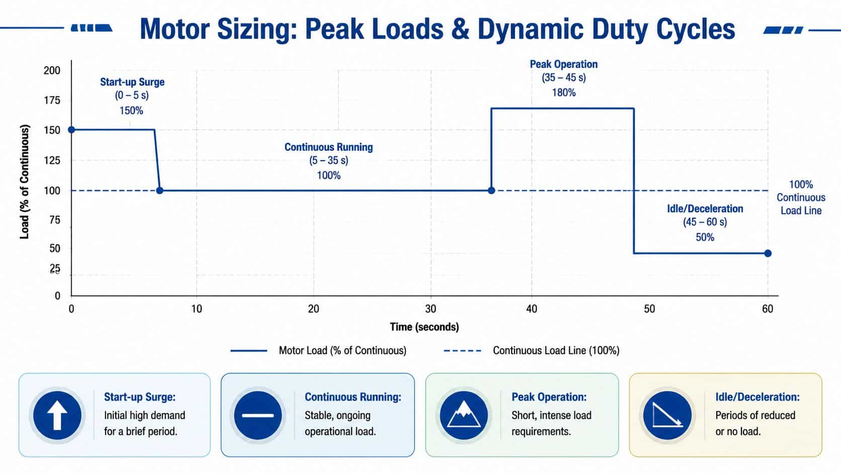
Why peak demand changes the answer
Hydraulic motors and electric motors behave differently under transient loading, but both suffer if you treat short bursts as irrelevant. Start-up torque, reversing events, product jams, high-inertia acceleration and operator-driven shock loads often determine the actual minimum motor size.
In UK variable-pressure applications, engineers often use root mean square horsepower rather than peak horsepower alone. The formula is hp_rms = √[(hp₁²×t₁ + hp₂²×t₂ + …) / (t₁ + t₂ + …)]. In a duty cycle of 15 hp for 30 seconds, 10 hp for 45 seconds, and 5 hp for 15 seconds, the RMS requirement is about 11.2 hp, which is well below the 15 hp peak. Used properly, that approach can reduce motor procurement costs by up to 20% while still matching the duty.
That matters because oversizing everything to the highest spike is lazy engineering. But undersizing to the average is worse.
Use RMS for variable work, not guesswork
Here's the practical divide:
- Peak load sizing only suits applications where the motor must continuously survive near-worst-case demand.
- RMS sizing suits cyclic operation where higher loads appear briefly and the motor has recovery time.
- Duty-cycle-based review is essential when thermal build-up matters more than the steady torque line on the spec sheet.
A lot of mobile machinery falls into the third category. Agricultural machines, lifting equipment and intermittent industrial units don't behave like neat continuous-duty workshop motors. They surge, pause, restart and surge again.
To see that behaviour in motion, this walkthrough is worth watching before you finalise a cyclic application:
Static safety factors aren't enough on their own
A fixed safety factor can help, but it doesn't replace duty analysis. In intermittent, high-inertia work, a motor may survive the average load and still overheat during repeated short bursts. That's where dynamic thinking beats rule-of-thumb sizing.
For mobile plant, I'd review these points before signing off:
- Burst frequency: How often does the machine hit high torque demand in a typical cycle?
- Thermal recovery: Does the motor get enough lower-load time to shed heat?
- Acceleration events: Is the machine repeatedly driving inertia, not just holding motion?
- Operator behaviour: Can the duty become harsher in real use than in the design assumption?
The practical lesson is simple. If the load varies, model the cycle. If the cycle is harsh, don't hide behind one continuous-duty number.
Matching Motor Type Gearing and Mounting
Once the load and duty are clear, the next question is hardware choice. At this stage, people often ask whether the machine requires an electric motor, a hydraulic motor, or a combination of motor and gearbox that shifts the problem into a more manageable speed range.
Electric drive versus hydraulic motor
Electric drives are attractive when you need predictable speed control, straightforward integration with modern controls and a relatively clean operating environment. They're often easier to monitor and tune when the machine duty is stable and the installation has reliable electrical infrastructure.
Hydraulic motors earn their keep when the machine needs high torque density, compact packaging, tolerance for hostile environments and strong performance under shock loading. In mobile and off-highway equipment, that combination is difficult to ignore.
Neither is automatically better. The right answer depends on the machine's job:
- Choose electric more readily for precision speed control, cleaner indoor settings and applications where wiring and control architecture are already in place.
- Choose hydraulic more readily where torque at low speed, compact drive packaging and rugged field operation matter more than laboratory-style efficiency.
- Use a hybrid view when an electric prime mover is supplying hydraulic power elsewhere in the machine and adding another electrical drive would complicate the build.
Why gearing usually improves the result
Direct drive sounds elegant, but it often forces you into a larger, slower and less forgiving motor. A reduction gearbox lets a motor operate in a speed range that suits it better, while delivering usable output torque at the driven shaft.
That usually means a more practical package and an easier parts shortlist. It also gives you another tuning lever. You can trade motor speed against output torque instead of trying to force one oversized motor to do everything alone.
If high output torque is the dominant requirement, reviewing high torque motor options alongside gearbox selection can save a lot of rework later.
A motor that looks perfect in isolation can become a poor choice once shaft loads, gearbox ratio and mounting geometry are added.
Mounting and fit are not admin details
This part gets left until too late far too often. Check the flange or foot mounting arrangement, shaft diameter, keyway, pilot dimensions, coupling type, allowable side load and available maintenance access before the order is placed.
A technically correct motor still becomes a bad selection if:
- the housing fouls nearby structure
- the shaft alignment is awkward
- the coupling can't tolerate the misalignment present in the machine
- service access requires half the machine to be dismantled
Good sizing ends with a motor that not only meets the duty, but also fits the machine properly.
Applying Safety Factors and Environmental Checks
A motor that works on the calculation sheet can still fail in service during the first cold start, the first summer heatwave, or the first week on a dirty site. This is the stage where a sensible selection gets protected against the conditions the machine will encounter, not the tidy conditions used for initial sizing.
Apply margin to pressure and flow, not just torque
For hydraulic systems, margin belongs in pressure and flow as well as torque. If you only protect the torque figure, you can still end up with a motor that pulls the load but misses target speed once hose losses, valve losses, oil temperature, or a later attachment change push the system away from the design point. Hydronit's hydraulic power unit sizing guidance makes this point clearly.
In practice, the right margin depends on how predictable the machine is. A fixed industrial installation with short pipe runs, stable ambient temperature and clean oil control can be sized tighter than a mobile hydraulic machine working outdoors in the UK, where cold starts, mud, water ingress and long hose runs are part of normal service.
Ask one question before sign-off. What happens at the machine's worst operating point?
That usually means checking hot oil and cold oil, relief setting tolerance, return backpressure, case drain conditions where relevant, and whether pump flow at real operating speed still supports the required motor speed. Electric drives need the same discipline, but the checks are different. There, the margin often sits around starting current, overload capacity, cooling method, inverter setup and supply quality rather than pressure and flow.
Environmental checks that catch expensive mistakes
Environmental review is where electric and hydraulic selections start to diverge quickly.
For electric motors, check enclosure rating, cooling path, dust loading, washdown exposure, cable entry, condensation risk and how the drive behaves in a hot panel. A standard TEFC motor that looks fine on paper can run hot if it is boxed into a poor enclosure or covered in product dust that insulates the frame.
For hydraulic motors, contamination control and oil condition usually decide service life as much as nominal rating. Review these points before approval:
- Ingress exposure: Rain, washdown, fertiliser, mud, salt spray, grain dust and metal fines all affect sealing and corrosion risk.
- Ambient and oil temperature: Cold oil raises pressure loss and can make starting sluggish. Hot oil reduces viscosity and film strength.
- Duty location: Indoor factory equipment, quarry plant and agricultural machinery create very different failure modes.
- Maintenance access: If filters, breathers, couplings, hoses or case drain lines are awkward to inspect, small faults stay in service too long.
- Shock and vibration: Mobile equipment sees loads that a stationary industrial skid often does not.
These are not admin checks. They change what survives.
Thermal thinking beats random oversizing
Oversizing can help, but only when it addresses the true limit. A larger electric motor may run cooler under the same load, yet it can also cost more, operate further from its best efficiency point and create control issues at low load. A larger hydraulic motor may reduce pressure demand, but it also needs more flow for the same speed, which can push you into a larger pump, more heat rejection and a bigger reservoir.
Use margin where the application needs it. Do not scatter it everywhere and call it safe design.
I tell junior engineers to watch for the failure pattern, not just the rated number. Electric drives usually complain through temperature rise, insulation ageing, nuisance tripping or poor low-speed performance. Hydraulic motors usually complain through hot oil, internal leakage, noisy running, seal distress and shortened bearing or gear life. The right safety factor addresses the actual failure mode the machine is likely to see.
Final Selection Checklist and Expert Collaboration
A motor usually gets chosen twice. First on paper, then again in service. The first choice happens in the spreadsheet or catalogue. The second happens on a cold start, on a hot afternoon, with worn couplings, pressure losses in the lines, and an operator who does not use the machine gently. Final selection needs to survive the second test.
The shortlist before you buy
Before issuing a purchase order, check the whole drive line, not just the motor nameplate. Electric and hydraulic selections fail in different ways. Electric drives usually expose bad sizing through heat rise, nuisance trips, poor starting performance or a VFD setup that never feels settled. Hydraulic motors tend to expose it through high oil temperature, pressure spikes, leakage, case drain trouble and shortened seal or bearing life.
Use this shortlist and make sure each answer comes from measured or defensible application data:
-
Load verification
Confirm breakaway torque, running torque, acceleration torque from inertia, and any external forces from gradients, belt pull, side load or driven equipment. -
Speed requirement
Check minimum, normal and maximum speed. Also check how long the motor spends at each point. A drive that looks fine at nominal speed can struggle badly at crawl speed or during repeated starts. -
Power with losses included
Keep the same efficiency assumptions used in the sizing work. Do not switch back to ideal figures once quotes arrive. -
Peak duty review
Review overload duration, start frequency, reversing duty, stall risk and shock loading. This matters more on mobile hydraulic equipment than many first-pass calculations allow for. -
Mechanical integration
Verify mounting face, shaft form, coupling selection, gearbox input limits, overhung load, hose or cable routing, and service access. -
Environment and protection
Check ambient temperature, contamination level, washdown or weather exposure, corrosion risk, vibration and available cooling.
Read the curves, not just the headline rating
Catalogue front pages are sales tools. Selection happens in the performance curves, thermal limits and installation notes.
For an electric motor, that means checking the torque-speed curve, service factor, insulation class, cooling method, VFD compatibility and low-speed operation. For a hydraulic motor, it means checking the pressure limit, continuous and intermittent speed range, volumetric and mechanical efficiency, case drain requirement, and what happens near the edge of the operating map. A hydraulic motor that meets torque on paper can still run too hot or too inefficiently if the duty point sits in a poor part of the curve.
As noted earlier, final checks should be made against published manufacturer data rather than nominal catalogue figures alone.
Where expert review earns its keep
A good applications engineer will usually test the assumptions that junior teams are most likely to miss:
- Whether the duty cycle is harsher than the description suggests
- Whether the available pressure, flow, voltage or current are still realistic once system losses are included
- Whether the load estimate is measured, inferred, or carried over from an older machine
- Whether the mounting and gearbox arrangement will introduce side load, misalignment or backlash problems
- Whether the machine needs margin for abuse, or only for normal production variability
Those conversations save money when they happen before the order is placed. I have seen projects where a small change in gearbox ratio made an electric motor easier to start and control, and others where a slightly different hydraulic displacement dropped operating pressure enough to improve oil temperature and seal life. Both looked acceptable in the first sizing pass. Only one would have stayed acceptable in service.
If your calculation and the manufacturer curve do not agree, stop there and resolve the difference. Do not average the two and hope for the best.
That is the practical answer to how to size a motor. Build the shortlist from the duty cycle, verify the operating points against manufacturer data, and make the final choice with the whole system in view. For UK mobile and industrial work, that usually means paying closer attention to intermittent duty, shock loading and thermal behaviour in hydraulic motors than a standard electric drive selection would require.
If you'd like a second set of experienced eyes on a motor sizing job, MA Hydraulics Ltd can help review the application, sense-check the assumptions and point you towards a practical hydraulic solution for mobile or industrial use. Phone 01724 279508 today, or send us a message.
