
A loaded cylinder on an agricultural telehandler should stay where the operator leaves it. Yet a machine can slowly lower even when the directional control valve appears centred and the pump is operating correctly. Internal spool leakage, actuator leakage, trapped pressure, or an unsuitable valve arrangement can allow the load to drift, creating a safety issue and an expensive fault-finding exercise.
A pilot operated check valve gives the actuator port a more positive hydraulic lock. It permits flow in the intended direction, then blocks reverse flow until a deliberate pilot signal releases it. That makes the valve particularly useful in cylinder circuits where load holding, controlled movement and predictable release matter more than having the simplest possible plumbing arrangement.
For UK OEMs and MRO teams, the decision is not just whether to fit a check valve. The key questions are whether the valve suits the load geometry, how much pilot pressure the circuit can provide, whether the interface matches the existing manifold, and whether engineers can reach the valve when the machine needs servicing.
Understanding the Pilot Operated Check Valve
A direct check valve can stop reverse flow, but a cylinder circuit often needs more control than that. Consider a loaded boom or clamp. Oil must enter the actuator freely during one movement, while the return path must remain securely closed when the directional valve is centred. If the load tries to force oil back through the actuator line, the pilot operated check valve closes at the port and holds the oil in place.
The basic principle is straightforward. The valve allows free flow in one direction and blocks counter-flow until pressure is applied to its pilot port. Parker describes this arrangement for its C4V design, with free flow from A to B, blocked flow from B to A, and pilot pressure at control port X releasing the blocked direction in its UK technical documentation.
That distinction matters because a directional valve isn't always a perfect load-holding device. A spool can permit small internal leakage, especially as components wear or contamination damages the lands and edges. A pilot operated check valve places the primary blocking function close to the cylinder port, rather than relying solely on the centred position of a remote directional spool.
What the valve does in a cylinder circuit
The valve normally sits between the directional valve and the actuator. In a single-acting application, it can lock one cylinder port. In a double-acting application, engineers may use separate valves on both actuator lines, often with pilot connections arranged so that movement in one direction releases the opposing valve.
The result is a deliberate sequence:
- The actuator receives flow through the permitted direction of the check element.
- The load attempts to return oil when external force acts on the cylinder.
- The check element closes, stopping reverse flow at the actuator connection.
- The operator commands movement, causing pilot pressure to act on the release mechanism.
- The blocked passage opens, allowing controlled return flow through the directional circuit.
The hardened seat used in some UK-market CETOP 3, or NG6, valves is important here because it supports tight closing at the actuator port. A valve that holds reliably when clean and correctly installed can still fail to perform if the seat is damaged, the oil is contaminated, or the pilot passage cannot develop sufficient pressure.
Practical rule: Treat the pilot operated check valve as a load-holding component, not as a substitute for correct circuit design, filtration, guarding and safe maintenance isolation.
For a broader explanation of one-way hydraulic flow and conventional check valve operation, see this guide to what a check valve does. The pilot operated version adds an external release function, which is the feature that makes it suitable for controlled actuator locking rather than simple backflow prevention.
How Pilot Pressure Controls Reverse Flow
A cylinder on a modular CETOP manifold may show adequate system pressure yet refuse to lower its load. The usual cause is not the main check element. It is an incorrect or insufficient pilot signal. The pilot signal works like the key that retracts a deadbolt: without it, the valve stays closed even when the downstream circuit calls for movement.
In the free-flow direction, pump pressure acts on the check element and moves it away from its seat. The internal spring and pressure balance set the opening threshold, commonly called cracking pressure. That threshold should be considered when matching the valve to the available flow and pressure, particularly where a compact manifold includes several restrictions.
Reverse flow produces the opposite result. Load pressure pushes the check element onto its seat, preventing oil from leaving the actuator connection. The actuator remains hydraulically locked while the valve, seat, oil and surrounding circuit remain in suitable condition.
Pilot force and release pressure
Pilot pressure enters the control port and acts on a pilot piston, spool or related release mechanism. The mechanism transfers force to the main check element, allowing it to unseat against the pressure held on the blocked side. Once the pilot force is sufficient, oil can return through the passage previously closed by the check element. The directional valve still commands the movement, while the pilot operated check valve permits the return path.
The pilot ratio sets the pressure required at the control port relative to the pressure being held. A Parker SVLB datasheet specifies a 6:1 pilot control ratio, so the pilot side can use substantially lower pressure than the blocked side to release the valve. Review the SVLB pilot control documentation when checking how the pilot arrangement relates to valve operation.
Pressure shown on the main gauge does not confirm that the pilot piston is receiving the pressure needed for release. On a CETOP stack, the pilot may be connected to the wrong side of the directional spool, restricted by a small passage, or delayed by another valve. These faults are easy to miss because the load-holding function can continue to work while the release function fails.
What engineers should verify
Check the pilot source, pilot connection, directional spool centre condition and pressure at the instant release is commanded. The valve opens only when the force at the pilot mechanism exceeds the force keeping the check element seated. Confirm the pilot path during commissioning, and leave enough access around the modular valve for testing and later maintenance.
A valve that holds correctly but will not lower the load usually has a functioning load-holding side and a pilot circuit that cannot generate sufficient release force. Check pilot pressure at the valve, not only at the pump or manifold inlet, then inspect restrictions, spool configuration and contamination in the pilot passage.
The embedded video below shows the release sequence described above, with the pilot piston unseating the check element against blocked-side pressure. Its guidance on embedded web content accessibility also supports using a descriptive frame title and suitable alternative information.
Comparing Pilot Operated and Direct Acting Valves
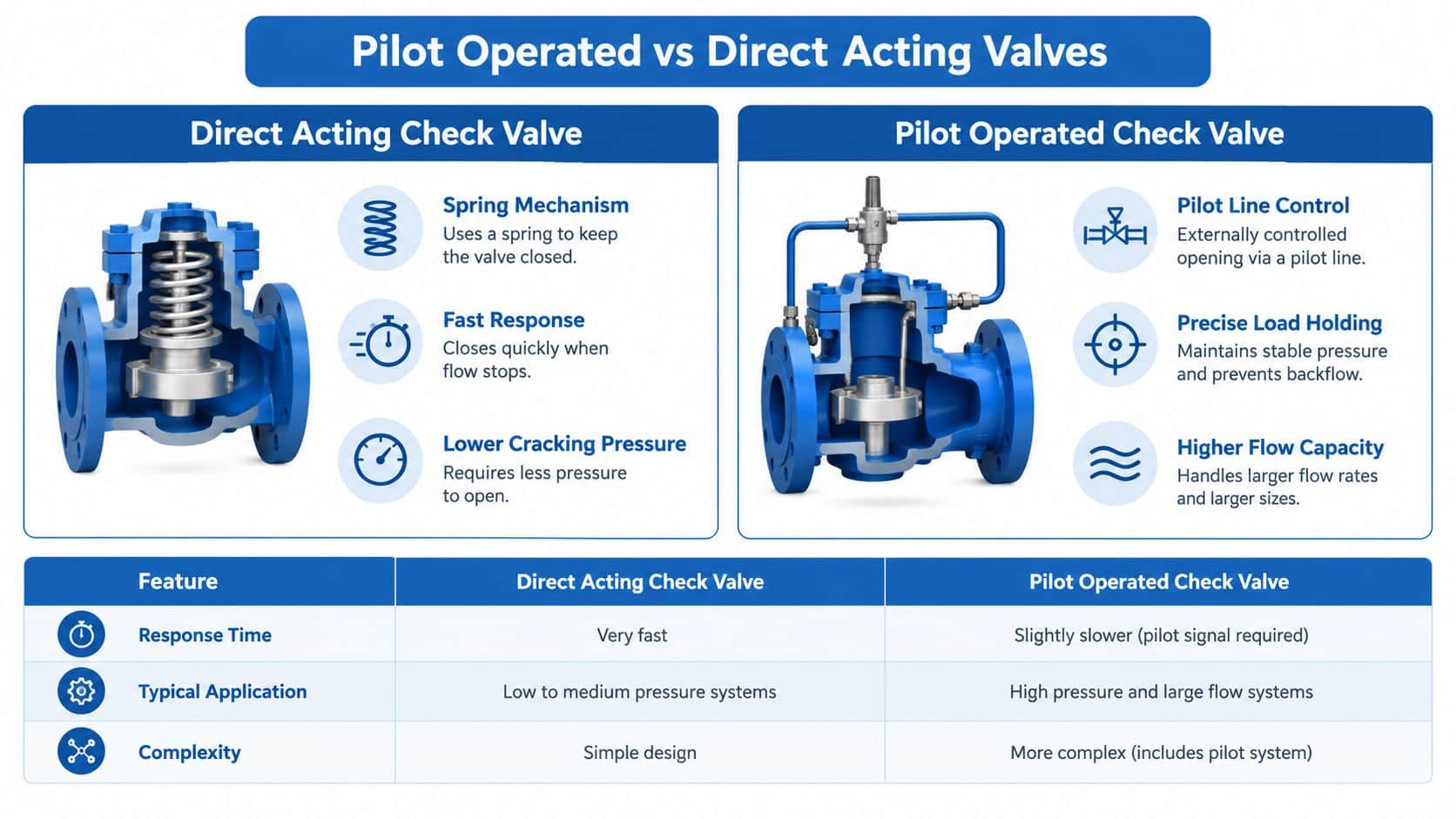
The right choice depends on what the valve has to achieve. A direct acting check valve is often the sensible option for pump outlet protection, simple return-line routing or preventing reverse flow in a low-complexity circuit. Its mechanism is compact and responds directly to pressure difference, without a separate pilot connection.
That simplicity becomes a limitation when the valve must hold a loaded actuator and then release it in a controlled way. A direct acting check valve doesn't normally provide the external hydraulic release that lets a directional valve command reverse flow through a locked actuator line. Adding separate plumbing or another valve may solve the problem, but the circuit can become less predictable and harder to service.
Load holding and leakage
A pilot operated check valve is designed to close the actuator port and hold the load until pilot pressure is applied. This makes it a strong candidate for cylinders on clamps, presses, lifting equipment and mobile plant where unwanted movement is unacceptable.
A direct acting valve can still provide effective non-return protection, but its suitability for load holding depends on the application, valve construction, seat condition, and the forces acting on the actuator. It should not be selected for a safety-critical load just because it has the correct port size.
Neither design excuses engineers from checking cylinder leakage, hose condition, mounting security or the performance of the directional valve. A pilot operated valve can stop flow through its own passage, but it can't repair internal leakage across a cylinder piston or a damaged hose.
Release and thermal behaviour
A trapped load can create a difficult release condition. Pressure may rise as oil warms, the actuator load changes, or the circuit closes both sides of a cylinder. If the pilot signal is too weak, the valve can remain locked. If the circuit has no suitable path for displaced oil, the operator may experience erratic or delayed movement.
Direct acting valves generally involve fewer control connections, so there are fewer pilot-line faults to investigate. Pilot operated designs introduce more components and therefore demand better circuit discipline, but that additional complexity gives the designer a positive release function and more controlled actuator behaviour.
A direct acting valve is simple because it has fewer functions. A pilot operated valve is useful because it performs more than one function.
Circuit complexity in practice
| Selection concern | Direct acting check valve | Pilot operated check valve |
|---|---|---|
| Reverse-flow prevention | Automatic closing against reverse pressure | Automatic closing with pilot-controlled release |
| Actuator load holding | Suitable for simpler duties when correctly sized | Suited to controlled cylinder locking |
| Release control | Usually requires another circuit function | Built into the pilot arrangement |
| Installation | Straightforward inline plumbing | Inline, dual or modular installation options |
| Fault finding | Fewer connections to inspect | Pilot pressure and release path must be verified |
The extra pilot connection isn't automatically a disadvantage. In a well-designed manifold, it can reduce external hosework and make the release sequence clearer. In a poorly documented retrofit, it can become another hidden failure point.
Selecting the Right Valve for Your Hydraulic Circuit
Valve selection starts with the load, not the catalogue photograph. Establish the actuator pressure, expected flow, mounting arrangement, available pilot pressure and the consequences of drift or delayed release. Then check the manufacturer's pressure, flow, temperature, seal and pilot-ratio data against the actual duty.
UK supplier specifications commonly show working pressures up to 350 bar, cracking pressure around 2 bar and pilot ratios such as 4:1. One UK specification also gives a temperature range from -28 to 100 °C, a relevant operating envelope for mobile plant and industrial machinery used through changing British conditions. These figures are listed in the UK pilot operated check valve specification, but they still need to be matched to the exact model and application.
Pilot ratio is a release decision
A high pilot ratio reduces the pilot pressure needed to release a valve against a given load pressure. That can help where the actuator geometry produces an unfavourable relationship between load pressure and pilot area, or where the available pilot signal is limited.
The ratio isn't a universal performance ranking. A higher value may improve release capability, but the designer still needs to consider pilot stability, the directional spool arrangement, back pressure and the way the valve is connected to the actuator. The correct ratio is the one that releases reliably without causing unwanted movement or an uncontrolled drop.
| Pilot ratio | Typical application | Load pressure scenario | Release characteristics |
|---|---|---|---|
| 3:1 | Compact CETOP 3 or NG6 cylinder circuits | Moderate load pressure with a dependable pilot source | Requires a stronger pilot signal than higher-ratio designs |
| 4:1 | General mobile and industrial load-holding circuits | Load pressure where standard pilot supply is available | Balanced release requirement for common cylinder duties |
| 6:1 | Higher-load or less favourable actuator geometry | Greater blocked-side pressure relative to available pilot pressure | Releases with a lower pilot pressure requirement |
| 8:1 | Applications with especially limited pilot pressure | Unfavourable load-to-pilot-area relationship | Maximises pilot leverage, but still needs correct sequencing |
The table reflects the range of ratios identified in UK-market specifications, including 3:1, 4:1, 6:1 and 8:1. The higher-ratio options and their application context are shown in this UK high-pilot-ratio valve range. Use the ratio as part of a force calculation, not as a substitute for one.
Flow capacity must match the actuator
A valve that's too small can restrict actuator movement, increase pressure drop and generate heat. A valve that's unnecessarily large may cost more, occupy valuable manifold space and make low-flow control less stable. Compare the rated flow with the cylinder's required flow in both directions, including the return flow created by rod-side and cap-side area differences.
UK listings include examples rated around 25 to 60 l/min at 300 to 350 bar, so those values illustrate the kind of specification range engineers may encounter rather than a universal selection target. The relevant catalogue data is available in this UK range of pilot operated check valves.
Also check cracking pressure. A low cracking value can support easier free flow, but it doesn't tell you how the valve will behave under load, during rapid deceleration or with contaminated oil. Confirm the actual pressure drop curves and installation orientation where the manufacturer provides them.
Integrating Modular Valves into Manifold Systems
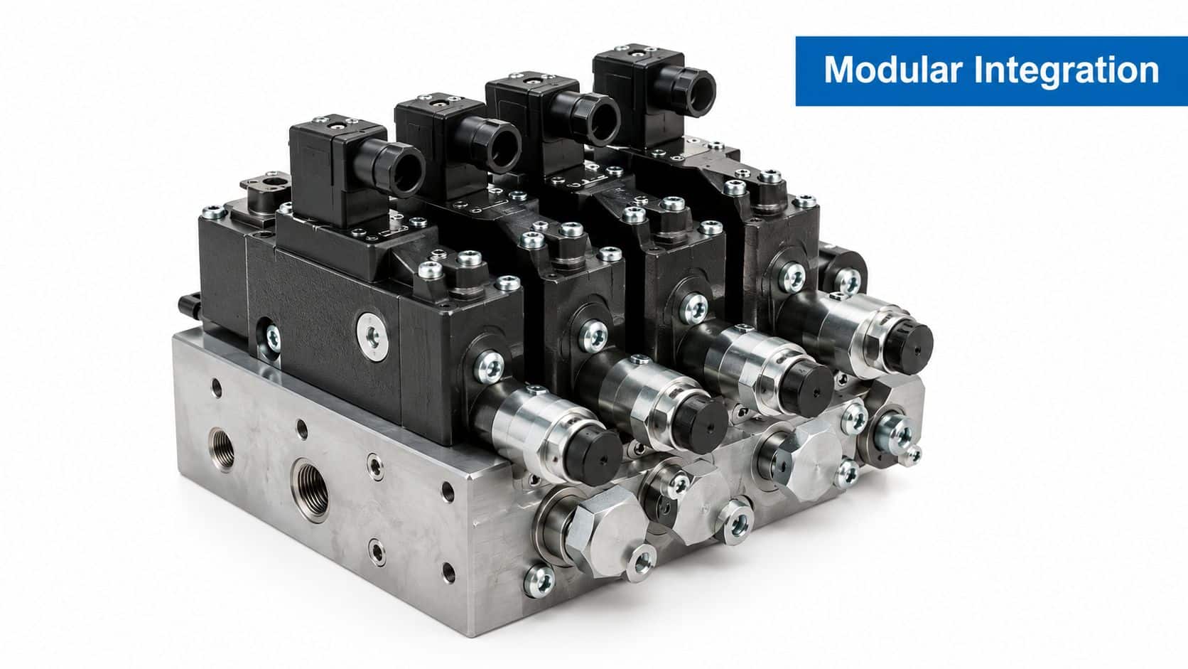
Inline valves are easy to understand because the pipework is visible. They can also create a long chain of fittings, hoses and adaptors, each adding a potential leak path and making the finished assembly harder to inspect. For modern UK OEM machinery, a modular pilot operated check valve can offer a cleaner way to place the load-holding function directly beneath the directional control valve.
A UK listing specifies direct mounting to UNI ISO 4401 / CETOP R 35 H4.2-4-03 for an NG6 modular system. That interface matters during both new design and retrofit work. The mounting pattern, port arrangement, stack height and pilot passages determine whether the valve will fit the existing assembly without machining, hose changes or a new manifold block.
CETOP integration and service access
A sandwich valve sits between modular elements in the stack. That arrangement can shorten the oil path from the directional valve to the actuator connection, reduce external tubing and keep the pilot circuit inside the manifold architecture. It also lets a maintenance engineer identify the valve by its stack position and interface, rather than tracing several hoses through a crowded machine.
Parker's UK SVLB literature describes cavity and mounting patterns according to ISO 7368, with sizes from NG16 to NG50, and identifies uses including keeping cylinders leak-free in position and handling return-line discharge where return flow exceeds directional valve limits. The same document gives a 6:1 pilot control ratio. These details are set out in the Parker SVLB UK literature.
The interface also affects retrofit feasibility. Before ordering, record:
- Mounting standard: Confirm the valve matches the existing UNI ISO 4401 or CETOP pattern.
- Stack arrangement: Check whether the directional valve, subplate and adjacent sandwich modules leave enough space for the chosen element.
- Pilot routing: Verify that the internal or external pilot connection follows the intended release sequence.
- Port orientation: Make sure actuator lines and drain paths align without forcing hoses into tight bends.
- Service clearance: Leave access for coil removal, fastener access, seal inspection and pressure testing.
MRO priority: A valve that fits the circuit but can't be removed without dismantling half the machine isn't a maintainable installation.
The modular approach isn't automatically superior. A compact stack can concentrate heat, hide contamination-related faults and make one incorrect spacer or seal visible only after commissioning. Engineers should document the stack order, identify each valve on the schematic and retain the correct seal kit and tightening information.
For a plain-language explanation of how valve blocks distribute and control hydraulic flow, refer to this guide to how a manifold valve works. The practical benefit is achieved when the physical manifold design, schematic and maintenance instructions all describe the same circuit.
Troubleshooting Load Holding and Release Issues
A drifting cylinder doesn't prove that the pilot operated check valve has failed. The fault may sit in the pilot line, directional spool, actuator, hose, contamination control or installation. Replacing the valve first can waste time and leave the original problem untouched.
Start with safe isolation and mechanical support. Never rely on a hydraulic lock alone while anyone is working beneath a suspended or raised load. Once the machine is safe, compare the observed symptom with the point in the operating sequence where the circuit stops behaving correctly.
If the load drifts
Check whether drift occurs with the directional valve centred, during heat soak, or only when the load changes direction. Inspect the pilot operated check valve for external leakage, then test the actuator and directional valve separately where the equipment design permits.
A contaminated seat can prevent the check element from closing fully. Damaged seals, incorrect assembly, loose mounting bolts or debris introduced during hose replacement can produce the same symptom. A hardened seat supports reliable closing, but it won't compensate for poor fluid cleanliness or physical damage.
The pilot line can also create a false impression of valve failure. A restriction, crushed tube, blocked orifice or incorrect connection may let the valve hold but prevent the intended release. In a dual-cylinder circuit, an incorrect cross-pilot arrangement can release one side too early or fail to release the opposing side at all.
If the load won't release
Confirm that the pilot port receives pressure at the right time, not merely that the pump gauge shows system pressure. A blocked-centre directional spool, an open-centre arrangement, an incorrectly selected spool or excessive back pressure can change the pressure available at the pilot connection.
Use a calibrated gauge at the pilot port during the release command if the circuit allows it. Compare the measured pressure with the valve's required pilot relationship and inspect the pilot passage for air, contamination and restrictions. Don't assume that a larger pilot ratio fixes every release problem. The signal still needs a sound source and a correctly routed path.
If lowering is erratic
Erratic movement often comes from pressure changes around the release point. Trapped air, hose expansion, an actuator load that changes through the stroke, or a return path with excessive restriction can all affect the feel of the machine.
A structured inspection should cover:
- Valve orientation: Confirm that the free-flow and blocked-flow directions match the schematic.
- Pilot connection: Trace each pilot line physically, especially after a retrofit or hose replacement.
- Spool centre: Check the installed directional spool against the circuit requirement.
- Fluid condition: Inspect filtration, oil cleanliness and evidence of damaged seat or seal material.
- Return flow: Consider rod-side and cap-side displacement, back pressure and the capacity of the return path.
- Mechanical load: Check for binding, side loading or an external force that changes as the actuator moves.
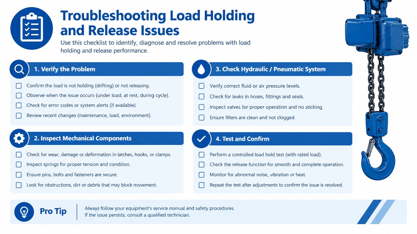
A useful diagnostic sequence is to isolate the symptoms rather than repeatedly cycle the machine. First establish whether the valve holds. Then establish whether pilot pressure arrives. Finally establish whether the downstream circuit provides a controlled return path.
For applications where cylinder locking is central to the design, review the available load-holding valves alongside the complete circuit rather than selecting a component by port size alone.
Securing Reliable Hydraulic Performance
Reliable load holding comes from matching the valve to the complete circuit. Confirm the blocked-side pressure, actuator geometry, required flow, cracking pressure, temperature range, seal compatibility and pilot ratio before approving the specification. A 3:1 arrangement may suit one compact NG6 circuit, while a higher-ratio valve may be more appropriate where the available pilot pressure is limited by the actuator geometry.
The mounting method deserves the same attention. A modular UNI ISO 4401 or CETOP installation can reduce external plumbing and simplify stack-based service, but only when the interface, pilot routing and valve order are documented. Inline, dual and manual-release versions remain useful where an existing machine has no suitable sandwich stack or where direct access is more important than compactness.
For OEM and MRO work, the best purchasing decision is rarely the lowest catalogue price. It is the configuration that holds the actuator reliably, releases predictably, fits the available space and can be diagnosed without unnecessary machine disassembly. MA Hydraulics Ltd supplies pilot operated check valves and related hydraulic components, and can support component selection for replacement valves, manifolds and bespoke power solutions.
MA Hydraulics Ltd can help you specify a suitable pilot operated check valve, CETOP modular assembly or complete hydraulic power solution for mobile and industrial equipment. Visit MA Hydraulics Ltd, phone 01724 279508 today, or send the team a message with your valve details, circuit requirements and service constraints.
