
A mobile machine has to lift, tilt and run an auxiliary attachment from one hydraulic power source, but there's barely enough room for another hose, let alone a bank of separate line-mounted valves. When a function then moves slowly, refuses to shift or operates inconsistently, the manifold can look like one complicated failure point.
It isn't. Manifold valve working becomes much easier to understand when you treat the block as a hydraulic routing system, not a metal mounting plate. Internal galleries connect the supply, return and service ports, while directional, pressure and flow-control valves decide where oil goes and under what conditions.
For UK OEM and MRO teams, that distinction affects design, procurement, commissioning and fault-finding. UK hydraulic practice treats manifold-mounted directional, flow and pressure control valves as a standard architecture for compact systems, with safety and manufacturing requirements extending beyond the choice of valve itself, as set out in this UK hydraulic assemblies standard.
Introduction to Manifold Valve Working in Modern Hydraulics
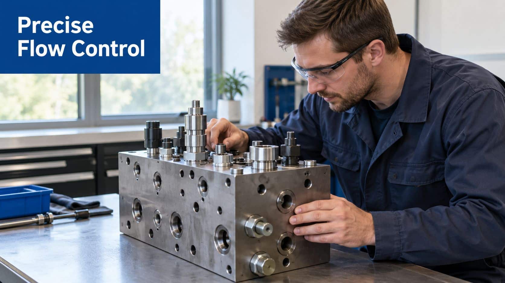
A manifold combines several hydraulic functions in a machined block. Instead of connecting every valve with separate hoses, adaptors and fittings, the designer drills internal passages through the block and mounts the valves directly onto prepared faces or inserts cartridge valves into dedicated cavities.
That arrangement gives the circuit a defined physical layout. Pressure enters through a common inlet, internal galleries feed the control valves, service ports connect to actuators, and return oil travels back through a shared low-pressure route. The result is a compact control centre for cylinders, motors, clamps and auxiliary functions.
Space is only part of the reason UK engineers use this architecture. Fewer external connections can reduce potential leak points, while standardised interfaces make replacement and integration more predictable. CETOP 3, also known as ISO 4401 NG6, and CETOP 5, also known as NG10, are widely used interfaces for directional valves and manifold blocks in UK hydraulic applications, supporting modular assemblies across manufacturers, as shown by UK CETOP valve information.
Why the block matters to the whole machine
A manifold doesn't merely hold valves together. Its galleries influence pressure loss, its seals must withstand the system pressure, and its mounting pattern determines whether the selected valves will connect correctly. A poor porting strategy can make a reliable valve behave badly, particularly when return pressure, transient loading or contamination affects spool movement.
The same principle applies to a compact industrial power pack. MA Hydraulics manufactures bespoke industrial power packs up to 11 kW, so manifold decisions need to support the complete package, including pump output, actuator demand, service access and future modifications.
This guide uses metric units throughout. Where a supplier provides a pressure rating in bar, it's retained as the working engineering value. No USD pricing is used, so there's no misleading currency conversion to interpret.
Practical rule: Treat the manifold as part of the control circuit. Selecting the valve without checking the block, galleries, interfaces and return path leaves half the design unresolved.
How Internal Flow Paths and Porting Direct Hydraulic Power
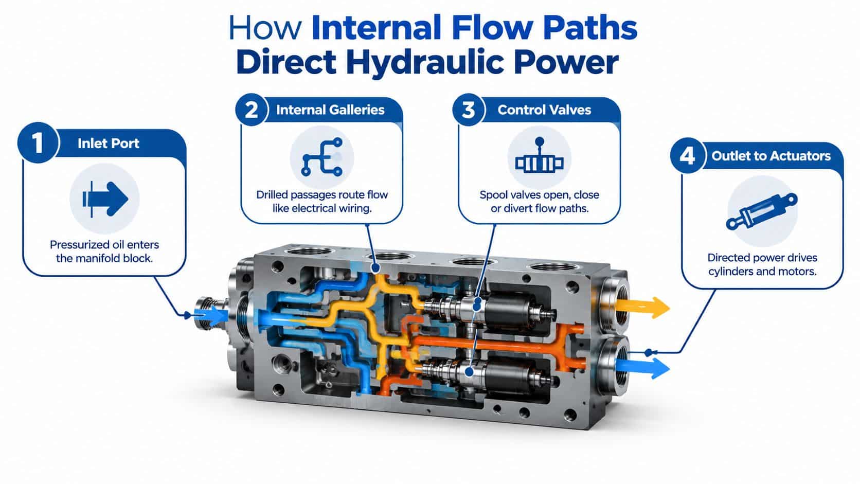
A hydraulic manifold is best understood as a drilled metal block containing a network of galleries. It normally has a pressure inlet, a tank or return outlet, and service ports that lead to actuator connections. Valves mounted on the block open, close or redirect those internal routes.
The electrical analogy is useful. A circuit board uses switches or transistors to direct current through different branches. A hydraulic manifold uses spools, poppets and cartridge elements to direct pressurised oil through drilled passages. The oil is the energy carrier, the galleries are the wiring, and the valves determine which branch is active.
A manifold valve is a hydraulic switch, but the block determines which routes are physically available.
Following the oil through the block
Start at the pressure port, commonly marked P. Oil from the pump enters this gallery and becomes available to the directional control valves. Depending on the spool position, the valve may connect P to service port A, P to service port B, or isolate the work ports.
The two service ports normally connect to opposite sides of a double-acting cylinder or to the working ports of a hydraulic motor. If P connects to A, oil enters one side of the actuator and the opposite side discharges through B. Reversing the spool swaps those connections, allowing the actuator to move in the other direction.
Return oil generally travels through a tank port marked T. The manifold gathers return flow through its internal passages rather than requiring a separate return hose from every valve. This concentrates the flow paths in one machined body, which can reduce variation caused by different hose lengths, fittings and external connections.
The hydraulic manifold design guidance from MA Hydraulics is relevant when the circuit needs a deliberate cavity arrangement, cartridge selection or porting strategy rather than a standard valve stack.
Why porting accuracy affects performance
A gallery has to carry the required flow without creating unnecessary restriction. The block also has to preserve the correct relationship between pressure, tank and service passages. If a return route is undersized or exposed to excessive backpressure, the valve may not behave as intended even though the supply pressure looks correct.
That's why a manifold should be assessed as a complete fluid-routing component. The internal geometry, sealing surfaces, valve interface and external port arrangement all contribute to the final result. Fewer hoses can simplify the installation, but it doesn't remove the need for careful design and testing.
The video below can help reinforce the relationship between valve positions and hydraulic routing. Embedded media should be checked in the page editor to confirm that its frame keeps the intended 16:9 aspect ratio and doesn't render with incorrect sizing.
Common Manifold Valve Types and How They Differ
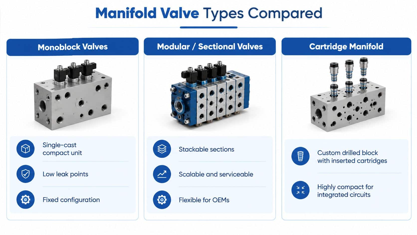
The three architectures most often confused in practical discussions are monoblock, sectional and cartridge manifold systems. They can all control hydraulic flow, but they place the balance between compactness, flexibility and serviceability in different places.
A monoblock valve is a single cast or machined body containing several valve sections. It suits a fixed machine design where the number and order of functions are already known. Because the functions share one body, the assembly can be compact and has fewer inter-section connections, but changing the configuration may require replacing the complete unit.
Sectional valves use separate sections bolted together into a stack. A designer can arrange functions in a specified order, and a maintenance team can often replace an individual section rather than the entire bank. That flexibility helps OEMs whose machines use different numbers of services, although the stack introduces interfaces that must be correctly sealed and tightened.
Cartridge valves sit inside cavities machined directly into a manifold block. This gives the designer considerable freedom over the circuit and can produce a highly integrated assembly. The trade-off is that cavity dimensions, cartridge compatibility, test access and contamination control become especially important during design and maintenance.
Standard interfaces and replacement decisions
CETOP mounting patterns support modular construction because compatible valves from different manufacturers can fit the same interface. UK suppliers commonly identify CETOP03, NG6, and CETOP05, NG10, for manifold applications, as shown in UK manifold valve catalogue information.
| Architecture | Best For | Flexibility | Serviceability |
|---|---|---|---|
| Monoblock | Fixed multi-function machines | Lower once manufactured | Replace the complete body or defined assembly |
| Sectional | OEM platforms with changing functions | High, sections can be arranged or exchanged | Individual sections can be accessible |
| Cartridge manifold | Integrated, custom hydraulic circuits | High at design stage | Depends on cavity access, cartridge availability and test points |
Pressure capability still depends on the actual product, material, seals and application. UK catalogue data lists steel manifold blocks around 345 bar maximum working pressure, while some aluminium CETOP 3 manifolds are rated at 210 bar and have a maximum flow of 40 L/min, according to this UK hydraulic valves and pumps catalogue. Those figures aren't interchangeable. The block rating must match the attached valve and the machine's real pressure behaviour.
Reading Hydraulic Schematic Symbols for Manifold Valves
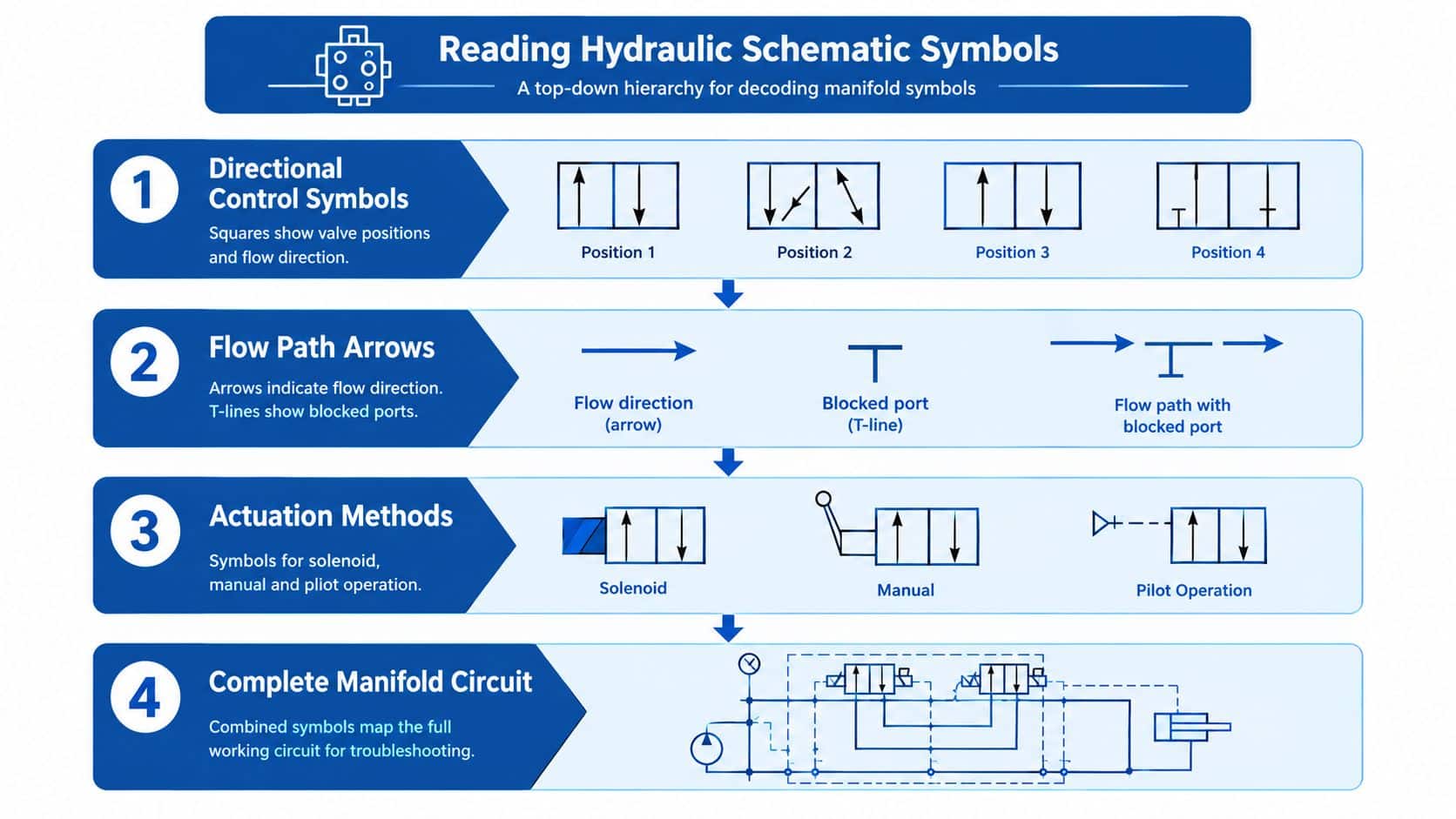
A schematic is the quickest way to understand what a manifold valve should do before anyone removes a coil or loosens a hose. Read it as a map of connections, not as a collection of isolated symbols.
Directional control valves are usually represented by adjacent square boxes. Each box shows one spool position. Arrows inside the box show which ports connect when that position is active, while T-shaped lines indicate blocked passages.
For a typical valve, identify the pressure connection P, tank connection T, and work connections A and B. Trace the arrows in the selected box. If P connects to A and B connects to T, the actuator moves in one direction. If P connects to B and A connects to T, it moves in the opposite direction.
Recognising the actuation method
The symbol at each end of the directional valve shows how the spool shifts. A solenoid symbol indicates electrical actuation, a lever indicates manual operation, and a pilot connection indicates hydraulic or pneumatic pilot control.
This distinction matters during fault-finding. If the schematic shows a solenoid-operated valve, a no-shift fault needs an electrical check before a hydraulic strip-down. If it shows pilot operation, the pilot supply and pilot pressure become part of the first diagnostic checks.
Centre conditions reveal hidden behaviour
The centre box of a three-position directional valve deserves particular attention. A blocked centre can close P, T, A and B, holding oil in the actuator lines but also preventing pump flow unless another unloading route exists. A tandem centre typically connects P to T while blocking A and B, allowing the pump to unload while the actuator remains held.
Don't assume the drawing is self-explanatory. Check whether the centre condition matches the pump type, pressure-compensated controls and actuator-holding requirement. The hydraulic circuit symbol reference can support cross-checking when a drawing uses unfamiliar directional, check, relief or pilot symbols.
Reading habit: Trace P, then trace T, then follow A and B. This sequence exposes blocked centres, unintended tank connections and missing actuator return paths before commissioning.
Functional Examples in Mobile and Industrial Systems
A compact agricultural or materials-handling machine may use one pump for lift, tilt and an auxiliary function. A sectional valve bank organises these services in one assembly. The pump gallery feeds the active valve section, while the tank gallery collects return oil. The machined block acts like a road junction, with each spool position selecting the route to an actuator.
Shift the lift spool and pressure oil travels from P to the selected lift-cylinder port. Oil leaving the opposite chamber returns through the other work port and then reaches T. Return the spool to centre and the internal connections change. The cylinder may hold position or the pump may unload, depending on the centre condition shown on the schematic.
Tilt and auxiliary sections follow the same routing logic. Their spool positions decide which actuator receives flow, while the manifold keeps the passages close together. That reduces external hosework around a mobile machine, where vibration, impact and restricted space make long hose runs harder to protect and service.
For OEM teams, the practical question is whether the block layout matches the machine's service order and diagnostic access. For MRO teams, a section that fails to move can be assessed by tracing the relevant gallery and work ports, then checking the spool, actuator and return route without dismantling unrelated circuits.
An industrial power pack example
A press or workholding fixture may use a compact CETOP manifold that combines directional control with relief and check-valve functions. The pump feeds the pressure gallery, the relief valve limits the pressure condition, and a check valve can prevent reverse flow when the directional valve returns to centre.
Pressure class must be read across the complete assembly. One UK manifold block technical document specifies multi-station manifold operation to 315 bar, alongside aluminium block ratings up to 310 bar. An industrial hydraulic valve document specifies 350 bar on working ports. The manifold, valves, seals and fittings therefore need compatible ratings, including allowance for pressure transients.
Port size also affects the result. A steel CETOP 3 manifold catalogue example uses 1/2 inch BSPP P and T ports and 3/8 inch BSPP A and B ports. The circuit should still be specified using the required metric flow, pressure and actuator performance.
The gain is controlled routing, not a smaller footprint. One block gives directional control, pressure protection and load holding a repeatable relationship, helping designers validate the assembly before installation and helping service engineers isolate faults at defined connection points.
How to Choose the Right Manifold Valve for Your Application
Select the manifold from the machine's operating conditions, then match the valves and interfaces to it. The machined block contains the galleries that route hydraulic power, so its pressure capability, flow capacity and mounting arrangement affect the complete assembly. Repeated switching, rapid actuator deceleration and other transients also need consideration.
A practical review should cover:
- Pressure rating: Compare the block's maximum working pressure with normal operating pressure and transient loading. The weakest correctly rated component sets the limit for the system.
- Flow requirement: Relate actuator speed, valve flow capacity and gallery size. A high pressure rating does not guarantee acceptable flow performance or pressure drop.
- Interface: Confirm the valve standard, such as CETOP 3, NG6, CETOP 5 or NG10. Check the subplate pattern, port orientation, seals and available cavity arrangement.
- Return conditions: Review the return path separately from the pressure supply. A workholding application shows why T-line routing and backpressure require their own check. Return pressure can affect clamping performance, valve operation and component life, so confirm the limit stated for the chosen circuit.
- Service access: Leave room to remove coils, inspect connectors, reach test ports and replace cartridges or sectional elements without dismantling unrelated pipework.
- Future diagnostics: Decide whether pressure transducers, position feedback or electronic diagnostic modules may be needed later. These additions improve fault visibility, while also introducing wiring, connectors and further potential failure points.
CETOP standardisation can simplify OEM design and replacement, but it does not make every manifold interchangeable. Verify the mounting face, spool or cartridge function, port lettering and internal connection logic against the schematic. For MRO work, those details help identify whether a fault lies in the valve, the gallery routing or an external connection.
Manufacturing quality is part of the specification
A dependable manifold starts with a correctly manufactured block. One UK engineering standard requires manifold blocks to be one-piece fabricated, ultrasonically tested before hydraulic channels are drilled, and made from forged steel or qualified cast steel. It also limits stacked manifold blocks to three components maximum, specifies 30 bar reduced pilot pressure for NG25 and NG32 spool valves, and aligns maximum pressure-setting safety valves with ISO 4413.
The same standard gives safety valves a stated Mean Time To Dangerous Failure of 150 years. That figure applies to the specified safety-valve arrangement, not automatically to every manifold component. The practical lesson is broader: valve working depends on block construction, verification, pressure limitation and component arrangement as well as spool selection.
Request pricing in GBP for the exact block, valve configuration, seals, fittings and testing requirements. A lower component price may prove poor value if an incompatible interface, inaccessible cartridge cavity or unsuitable pressure rating causes redesign or extended downtime.
Installation Maintenance and Troubleshooting for Reliable Operation
Installation errors often appear later as valve faults. Keep the block and connected components clean, use the specified seals, tighten fittings to the manufacturer's torque requirements, and flush the circuit before placing sensitive spool or cartridge valves into service.
Confirm the supply and return connections against the schematic. Check that pilot-operated valves receive the required pilot pressure, that electrical connectors are seated correctly, and that the machine's control voltage reaches the coil under operating conditions. Guidance on inline valve installation is also useful when a manifold circuit includes adjacent line-mounted components.
A diagnostic sequence that avoids unnecessary replacement
When a valve won't shift, separate the possible causes rather than condemning the whole manifold.
- Electrical first: Check the control supply, connector condition, voltage at the coil and coil continuity. A loose connector or voltage drop can imitate a seized spool.
- Hydraulic next: Measure inlet and outlet pressure, then confirm pilot pressure where applicable. A blocked return or inadequate pilot supply can prevent the expected movement.
- Contamination check: Inspect oil condition, filters and the valve's accessible surfaces. Sticky spools and restricted orifices may result from contamination rather than damage to the manifold body.
- Isolate by section: Use test ports and isolate sections where the circuit permits. Compare the faulty function with a known working function instead of replacing several components together.
- Validate under load: A valve may shift with no load but fail when pressure, flow or actuator resistance rises. Test the suspected route under the machine's real operating condition.
Some multi-station steel manifolds can use blanking plates when a valve position is removed, allowing the remaining stations to operate. That can preserve machine function during a planned repair, provided the blanking arrangement matches the block and the unused passage is safely sealed, as shown in UK manifold block product information.
A diagnostic-first approach saves time because intermittent shifting may come from wiring, pressure loss, contamination or pilot behaviour. Replace the valve only after the electrical and hydraulic evidence points to it.
If you need help matching a manifold, CETOP valve, cartridge circuit or bespoke power pack to your application, contact MA Hydraulics Ltd on 01724 279508 today, or send a message through the contact page.
MA Hydraulics Ltd can help OEM and MRO teams with manifold component selection, cross-references, block design support and bespoke power-pack requirements. Visit MA Hydraulics Ltd to discuss pressure ratings, CETOP interfaces, service access and a practical hydraulic solution for your machine.
