
The most popular piece of advice about hydraulic flow dividers is that a 50/50 valve keeps two cylinders moving in step. It's tidy, it's easy to quote, and on a machine with unequal loads it's wrong often enough to waste a morning.
A divider apportions flow by ratio. It doesn't know what load each branch is carrying, and it doesn't react when one cylinder bottoms out and the other keeps travelling. Buying on the ratio alone is how good valves end up carrying the blame for bad circuits.
What follows is how these valves split and rejoin flow, which type suits which duty, and the four readings that prove the split on your own machine before you sign the work off.
How a Flow Divider-Combiner Valve Splits and Rejoins Flow
A hydraulic flow divider does not just split a stream in two. Its internal element sets how much oil goes to each outlet, while the circuit determines what each actuator can do with that flow.
The flow path works like a road junction. In divider mode, oil entering the valve is apportioned between two outlets. In combiner mode, flow from two branches meets inside the valve and leaves through one outlet. The same valve body can often perform both functions, depending on the direction of flow, so check the port markings before connecting it.
The Four-Step Flow Path
- Oil enters the inlet at the pump's delivery rate, measured in litres per minute (L/min).
- An internal element apportions the flow between the outlets. Depending on the valve, this may use gear sets on a common shaft, a pressure-compensated spool or fixed metering orifices.
- Each branch supplies an actuator, such as a cylinder or motor.
- In combiner mode, flow reverses through the valve. Oil from both branches joins and leaves through one outlet.
For example, a 40 L/min pump feeding two equal-bore cylinders through a 50:50 divider supplies roughly 20 L/min to each branch when the loads match. That is the intended split. It does not guarantee equal actuator speed if the loads differ.
The diagram shows the split and the reverse-flow merge.
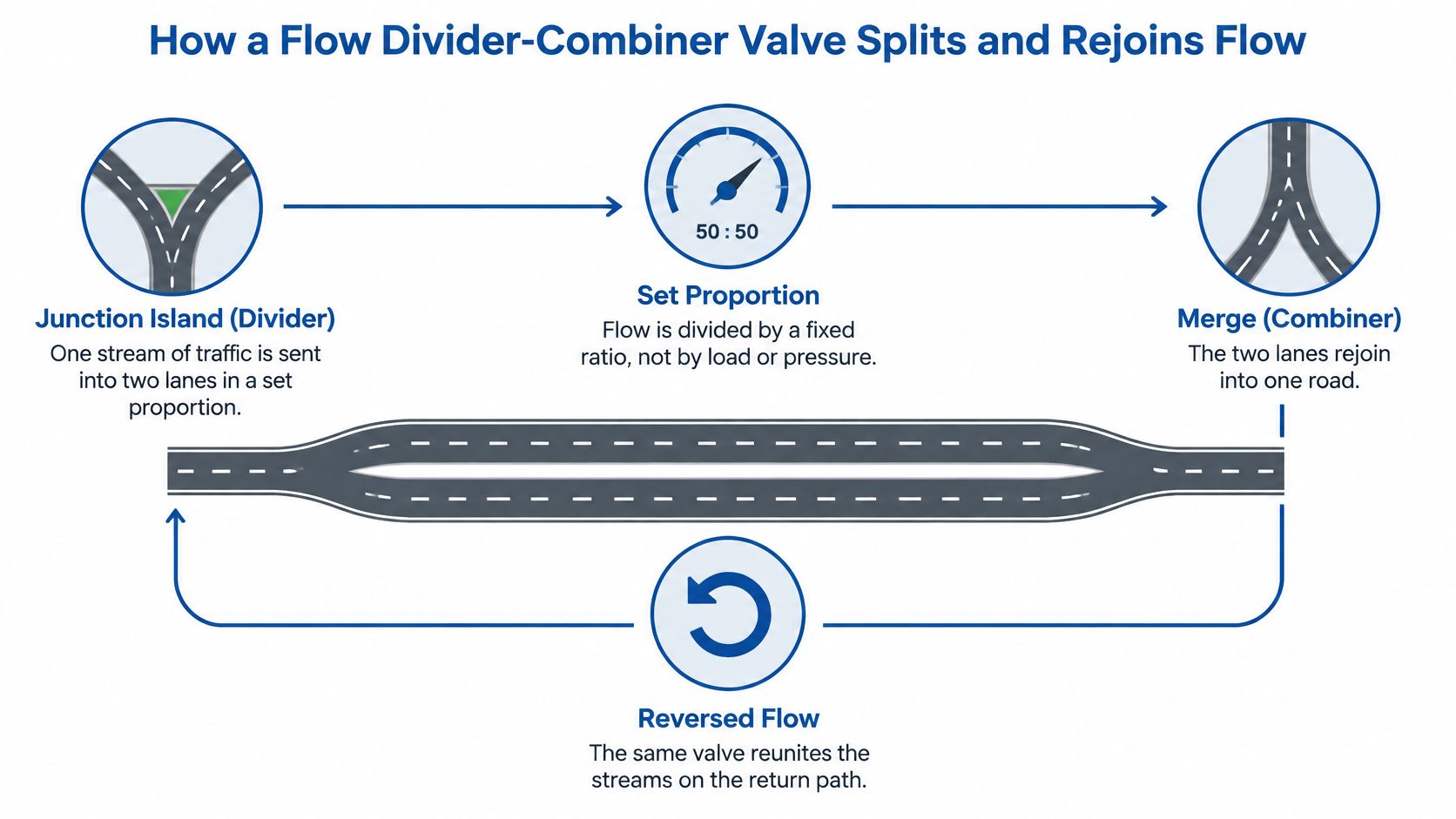
On the diagram: check every label against the port markings on your own valve. A mislabelled inlet can lead to an incorrectly connected circuit.
Record the inlet flow in L/min and whether the circuit needs division, combination or both. These details give you a useful starting point when selecting a valve.
Rotary Gear, Pressure-Compensated and Fixed Orifice Dividers Compared
Three divider types turn up on UK machines, and the combiner is a mode rather than a fourth family. The table sets out how each one splits flow and where it starts to struggle.
| Type | How it splits flow | Main strength | Main limitation | Typical use |
|---|---|---|---|---|
| Rotary gear divider | Two gear sets on a common shaft deliver fixed displacement shares | Simple, robust, fixed proportion | Shares drift if branch pressures differ or leakage rises | Equal-area cylinders or motors on mobile plant |
| Pressure-compensated spool divider | Spool senses branch pressure difference and throttles to hold equal flow | Holds the share better as loads change | Needs pressure margin and is more complex | Unequal or varying loads, such as one cylinder stalling |
| Fixed orifice divider | Fixed restrictions create a flow share that varies with load | Low cost and simple | Share shifts with pressure and oil temperature | Non-critical splitting where precision isn’t needed |
| Combiner operation | Two inlets merge into one outlet | Raises available flow for a single fast function | Doesn’t limit maximum reverse flow | Speeding up one function or returning cylinders faster |
Where Each Type Earns Its Place
A rotary gear divider holds its ratio through displacement, so the split stays close to the badge when both branches run at similar pressure. Raise the pressure on one side and a little oil slips past the gears to the other, which is why a worn gear set shows up as drift rather than a hard failure.
A pressure-compensated spool divider senses the difference between branches and throttles the faster side to keep the share. It needs a pressure margin above the highest branch load to work at all, so a circuit running close to its relief setting defeats it.
A fixed orifice pair is the cheapest way to split a flow and the least accurate. Viscosity changes with oil temperature, so a share that reads well cold can be several litres out once the machine is at working temperature.
Combiner mode is a plumbing change, not a control function. It won't cap reverse flow, so a cylinder returning under load can overshoot its speed. Where one function needs guaranteed priority over another, a priority flow divider valve is the different component you want.
Two checks settle most of the choice. Confirm the rated flow in L/min and the operating temperature range in °C, then confirm whether the branch loads will stay equal or can differ under normal work.
Why a 50/50 Split Does Not Guarantee Matched Speed
Circuits and catalogue pages part company here. A pressure gauge on one branch tells you more about synchronisation than the ratio badge ever will.
What Actually Sets Actuator Speed
Cylinder speed comes from flow entering the bore against the load it's pushing. The divider controls the flow half of that equation and nothing else. The actual split depends on leakage, the pressure difference between branches, oil viscosity, component tolerances, branch restriction and the load-induced pressure in each branch, as the rotary flow divider guidance from MA Hydraulics sets out.
Now stall one cylinder. It reaches the end of its stroke, or a load stops it. The divider keeps sending its share towards the free branch until pressure builds enough to matter, so the free cylinder accelerates while the stalled one sits still. Nothing has failed. The valve is doing exactly what a ratio device does.
A divider apportions flow. It never apportions load.
The safety gap sits underneath that. The divider isn't over-pressure protection, so each branch may need its own relief or pressure-limiting valve where an actuator can lock or reach the end of its stroke. A combiner doesn't regulate maximum reverse flow either, so returns and overrunning motors need flow control.
The Video Walk-Through
The clip below shows the behaviour on a live machine, which is easier to follow than any diagram. Frames on embedded players are often rendered at the wrong size, so check the player renders correctly on both mobile and desktop, with usable controls and sensible sizing, as the UK guidance on formatting video content recommends.
Prove the split on your own machine rather than trusting the badge. Record all four readings below under matched loads and again with a deliberately unbalanced load, and keep the sheet with the machine history.
| Reading | What it reveals | How to record it |
|---|---|---|
| Inlet flow (L/min) | Whether the pump supply matches the valve rating | Flow meter at the inlet port |
| Outlet flow, branch A and branch B (L/min) | The actual split under balanced and unbalanced loads | Flow meter on each outlet at operating temperature |
| Port pressures (bar) | The pressure difference driving imbalance between branches | Gauges at each outlet port |
| Oil temperature (°C) | Viscosity change that shifts leakage and the split | Sensor or thermometer at the reservoir |
Matching a Divider-Combiner to Your Application
A divider rated for a 50/50 split will not necessarily keep two actuators moving at the same speed. Choose it for the actual duty, then check its performance on the machine.
Five Steps Before You Shortlist a Valve
- Calculate the flow each actuator needs in L/min, including the combined flow required for any faster function. The flow rate calculation guidance covers calculations using bore, stroke and cycle time.
- Record maximum working pressure in bar, using the circuit's relief setting as the ceiling.
- Compare expected branch loads. Note any risk of an actuator stalling or reaching the end of its stroke while the other continues moving.
- Assess contamination and exposure. Field dust and water ingress can affect the conditions a valve must withstand.
- Check group size and mounting against the required flow and the space available around the valve.
Use those details to compare likely approaches:
| Application case | Likely valve approach | Key checks before specifying |
|---|---|---|
| Two equal-area cylinders with similar loads | Rotary gear divider | Inlet flow in L/min and rated working pressure in bar |
| Cylinders with differing loads or stall risk | Pressure-compensated divider, with suitable branch protection | Pressure margin across the divider and relief settings in bar |
| One function needing faster speed or return | Combiner operation | Reverse flow control and port sizes |
| Motors that can overrun | Divider with flow control on the return | Overrun flow in L/min and oil temperature range in °C |
| Dusty or wet field work | Filtered supply and a sealed design | Filter rating, service interval and contamination control |
Agricultural machines often run several functions during a working cycle. Check which functions operate together, how heavily they are loaded and how quickly the machine needs to return to service. Those details matter more than choosing a valve from flow capacity alone.
Relief Valves and UK Safety Requirements for Divider Circuits
A flow divider does not protect a circuit from overpressure. Fit suitable pressure-limiting protection wherever an actuator can be blocked or reach the end of its stroke. A divider can split the flow, but it cannot prevent pressure from rising when movement stops.
Cross-port relief can protect against pressure differences between ports. Flow control may also be needed where cylinders return or motors overrun. Include these operating conditions in the circuit design, rather than relying only on normal running behaviour.
What the UK Standards Ask For
BS EN 982:1996, published in 1996 and amended in 2008, set out safety requirements for hydraulic systems and their components. It was later superseded by BS EN ISO 4413:2010, as recorded in the British Fluid Power Association standards library. The Health and Safety Executive still lists BS EN 982:1996 to 2008 among machinery-safety standards for hydraulic systems. Older machines may therefore refer to it. Check the standard used for the machine before approving a circuit change.
Key rule: a branch that can be stopped by an outside force or an actuator end stop needs appropriate pressure protection.
Use this checklist when specifying the valve and circuit:
- Rated pressure in bar and rated flow in L/min.
- Pilot or load-sensing behaviour, if the circuit uses it.
- Leakage limits at operating temperature.
- Installation orientation, as shown on the datasheet.
- Filtration and contamination control, including service intervals.
- Failure modes, as well as nominal port size.
Protection sizing is separate from divider sizing. Use the pressure relief valve sizing guidance to calculate the required protection. MA Hydraulics offers OMT Group valves, including cross relief and flow divider/combiner valves.
Diagnosing Synchronisation, Heat and Flow Problems
A 50/50 divider can deliver equal flow at its outlets while unequal loads still leave actuators out of step. Use commissioning readings to separate a load-related speed difference from a restriction, leakage or divider fault.
Change one thing at a time, then record the inlet and branch flows, branch pressures and oil temperature in °C. Compare readings under balanced and unbalanced loads before dismantling the valve.
| Symptom | Likely cause | Check or corrective action |
|---|---|---|
| Actuators drift out of step under load | Unequal branch loads or leakage in one branch | Compare branch flows and pressures under load; check for leakage and restrictions |
| One branch runs hot or slow | Internal leakage or a restriction | Check leakage paths and the cooler’s capacity for the duty |
| Speed changes after warm-up | Lower oil viscosity as temperature rises, allowing leakage to increase | Check the operating temperature and specified oil grade |
| Pressure spikes when one cylinder stalls | No relief valve protecting that branch | Check that each branch has suitable relief protection set below the circuit maximum |
| Noise or pulsation at the divider | Air ingress or cavitation at the inlet | Check the inlet line, reservoir level and suction filter |
| Combined flow falls below rating | Contamination or wear in the divider element | Inspect the element and filtration; clean or replace it if needed |
Start with checks that do not require stripping the valve: inspect the inlet line and filter, look for air ingress, and check the branch relief settings. If the fault remains, inspect for worn gears, a scored spool or other internal damage. Abrasive contamination may also show up in the filter or oil, so find the cause of wear before replacing parts.
A useful distinction is whether the outlet flows remain equal when branch pressures differ under an unbalanced load. If they do, check for a restriction or an incorrectly set relief valve before blaming the divider. If one outlet flow falls, investigate leakage, wear or contamination inside the circuit.
Keep a dated record of each change and the readings before and after it. If a track drive seems laboured, compare hydraulic readings with the machine's mechanical condition; DirtPusher tips on track replacement cover the track side of that diagnosis.
If the fault returns, recheck contamination and branch loads before replacing the divider.
Confirm the Specification and Get in Touch
Before choosing a valve, confirm whether the circuit needs division, combination or both. Record the inlet flow in L/min and working pressure in bar, and state whether branch loads remain balanced or vary. Include the required branch protection and reverse-flow control.
Send the MA Hydraulics Ltd team those details, the oil temperature range in °C and a simple circuit sketch. Note which functions run together, how often they operate and what happens at the end of stroke. This helps the team match the valve type and group size to the duty.
MA Hydraulics stocks Vivoil hydraulic gear flow dividers in Group 0, Group 1, Group 2 and Group 3 sizes, including the Vivoil MIA-FD flow divider. Its range also includes OMT Group flow divider/combiner and cross relief valves. Send the flow, pressure, load pattern and oil temperature range to the team by phone or email to confirm a suitable option.
