
The machine's stopped, the old fitting is on the bench, and you're trying to order a replacement before the next shift. Searching for a 1 1 2 to 3 4 reducer brings up fittings that look much the same, but a matching size label doesn't mean they'll make the same pressure-bearing joint.
The expensive mistake isn't always buying the wrong thread. It can be fitting a low-rated socket into a hydraulic pressure line, choosing the wrong sealing arrangement, or letting swarf and tape fragments enter an otherwise sound circuit. Treat the reducer as part of the assembly, not just a way of joining different-sized connections.
What the 1 1/2 and 3/4 Sizes Really Measure
1 1/2 and 3/4 are nominal connection labels, not measured bore diameters. They identify a pipe or port family. They don't tell you the clear passage through the fitting, the outside diameter you'll measure with callipers, or how the joint seals.
The Hydraulics World reducing-socket listing illustrates the distinction: its nominal 1 1/2-to-3/4 socket is galvanised malleable iron, with a stated maximum working pressure of 25 bar and operating range of -20°C to +120°C. Those are limits for that product, not a rating you can transfer to every reducer carrying the same size description.
Measure the thread, not the label
Use callipers across the crests of an undamaged male thread. Then use a thread-pitch gauge rather than judging the spacing by eye. For a female port, check the equipment drawing or use suitable thread-identification gauges; measuring the opening alone won't establish the thread.
Dimensions to check for a 1 1/2 inch to 3/4 inch BSP and NPT reducer
| Check | 3/4 inch end |
|---|---|
| BSP parallel thread major diameter | Measure across male thread crests and compare with the BSP standard drawing |
| BSP thread pitch | Confirm with a BSP thread-pitch gauge |
| NPT thread outside diameter | Check against the NPT drawing at its specified measurement position |
| NPT thread pitch | Confirm with an NPT thread-pitch gauge |
| Steel pipe outside diameter | Measure the plain pipe, not the thread or socket |
Thread diameter and plain pipe outside diameter describe different surfaces. Taper threads also change diameter along their length, so the measurement position matters. A near match on callipers isn't permission to screw the parts together.
Record these four identification checks for each end:
- Diameter: Record the measured thread diameter and where you measured it.
- Pitch: Confirm the spacing with a gauge.
- Gender: State male or female explicitly.
- Form: Identify parallel or taper and the actual thread standard.
Ordering rule: A fitting that starts in a port hasn't proved that it belongs there.
Say the machine has a female BSPP port, but the order only gives the nominal sizes. A supplier could reasonably offer a reducer with a BSPT male end. That may be suitable for some pipework joints, but it doesn't establish compatibility with a hydraulic port designed for a parallel-thread fitting and a face seal.
Checking Thread, Pressure, Material and Documents Before You Buy
First settle what the notation means. For this purchase, you're specifying connection sizes, not a gearbox reduction ratio. Don't let a catalogue search substitute for identifying the actual joint.
Work through the purchasing checks
-
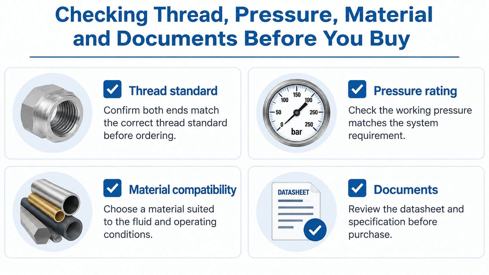
Confirm the standard at both ends. Identify BSPP, BSPT, NPT or metric, together with the sealing arrangement. Parallel hydraulic ports commonly rely on a bonded seal, O-ring or another designed sealing face; taper-thread joints use a different sealing principle. The guide to hydraulic fitting types helps distinguish the connection families before you order.
-
Read the complete pressure specification. Check the manufacturer's working-pressure rating for the exact part, material and temperature. A catalogue category such as industrial fittings doesn't establish suitability for a hydraulic pressure line.
-
Compare the fitting with the circuit conditions. Include the relief setting, normal pump outlet pressure and any foreseeable pressure spikes. Check the connected hose, adaptor, valve and port as well. A stronger reducer doesn't upgrade a weaker neighbouring component.
-
Match material and seals to the fluid. Give the supplier the actual oil or fluid designation, not hydraulic fluid. Include operating temperature and exposure to water, cleaning chemicals or outdoor corrosion. Don't assume that a metal body makes every seal inside it compatible.
-
Check the clear bore and duty. Ask for the internal passage dimensions and assess the required flow through them. Suction, return and pressure lines have different constraints, so a fitting accepted in one position may be unsuitable elsewhere. Use the machine or pump manufacturer's velocity and pressure-drop criteria rather than a generic rule.
These purchasing checks should stay with the job record, not just in a telephone conversation.
Establish responsibility and request documents
The HSE guidance on the Pressure Equipment (Safety) Regulations includes piping, fittings, couplings and hoses within pressure equipment, and explains that equipment with maximum allowable pressure above 0.5 bar can fall within the regulations. That doesn't mean every standalone reducer automatically requires a separate conformity assessment.
Ask who is confirming suitability for the complete assembly. For relevant equipment, the applicable conformity route, technical documentation and English-language instructions matter alongside any CE or UKCA marking that applies.
Request:
- A dimensional drawing: Including thread designations, sealing faces and clear bore.
- Written ratings: Working pressure, temperature limits and any service restrictions.
- Material identification: With a material certificate where the application requires traceability.
- Installation information: Seal specification, tightening instructions and applicable conformity documents.
Keep gearbox testing separate from fitting selection. The European approval methodology for drivetrain testing concerns controlled mechanical tests; it isn't a pressure-rating certificate for a hydraulic reducing adaptor.
Choosing Copper, Brass, Steel, Push-Fit or Threaded
Choose by fluid and pressure first, then by how the joint will be made. Convenience comes after compatibility. The easiest fitting to install isn't necessarily the easiest one to maintain safely.
Reducer types compared for a 1 1/2 to 3/4 transition
| Type | Typical material | Best use | Install method | Watch out for |
|---|---|---|---|---|
| Threaded galvanised malleable iron | Malleable iron with zinc coating | Water and compressed air within the product rating | Thread with approved PTFE tape or paste | Tape fragments and loose coating in oil circuits |
| Threaded steel | Carbon or stainless steel | Appropriately rated hydraulic lines and machine ports | Bonded seal, O-ring or sealant to suit the port | Mixing BSPP and BSPT sealing arrangements |
| Threaded brass | Brass | Suitable instrument, water and air lines | Thread with the specified seal or sealant | Overtightening a softer fitting |
| Copper solder or press | Copper | Water and heating pipework | Solder or compatible press tool | Tube outside diameter must match; doesn’t directly fit a threaded hydraulic port |
| Push-fit | Commonly brass or polymer, with a retaining collet | Approved water and low-pressure plumbing services | Push onto correctly prepared tube | Tube dimensions, fluid approval and retention requirements |
What works on the machine
Galvanised malleable iron is readily available for suitable pipework duties, but availability doesn't make it the default for an oil circuit. Loose coating and excess sealing material are avoidable contamination risks. I'd start with a purpose-rated hydraulic fitting rather than try to make a general pipe socket serve an undocumented duty.
Threaded steel is a practical option for machine ports and mobile equipment when its rating, thread and seal match the application. A bonded seal needs the correct seating surface. Adding tape to a parallel thread won't repair a damaged sealing face.
Brass is useful where its machinability and corrosion characteristics suit the service. It still needs a pressure rating, and a spanner can damage it if the installer treats it like a heavier steel fitting.
Copper and plumbing push-fit reducers are normally selected around tube outside diameter. Don't translate a nominal threaded size directly into a copper tube purchase. Press fittings also need the correct tool, jaw profile and approved tube.
Choose the fitting system that belongs on the machine, not the fitting that happens to be in the van.
For example, a mobile-plant return line being repaired in a yard is generally better served by an appropriately rated threaded steel adaptor than an improvised plumbing push-fit. The latter needs suitable tube, a square cut, an undamaged retaining mechanism and explicit approval for the service. Neither option excuses poor pipe support or a hose pulling sideways on the port.
How to Install the Reducer Without Contamination
Treat installation as a clean-fit procedure, not a tightening exercise. You can assemble a mechanically sound joint and still damage the system by introducing grit, fibres or sealant.
Hydraulics & Pneumatics guidance on contamination management attributes roughly 70–80% of hydraulic failures to contamination and recommends selecting cleanliness targets for the most sensitive component. That makes protecting open connections a central part of the repair.
Prepare, protect and assemble
-
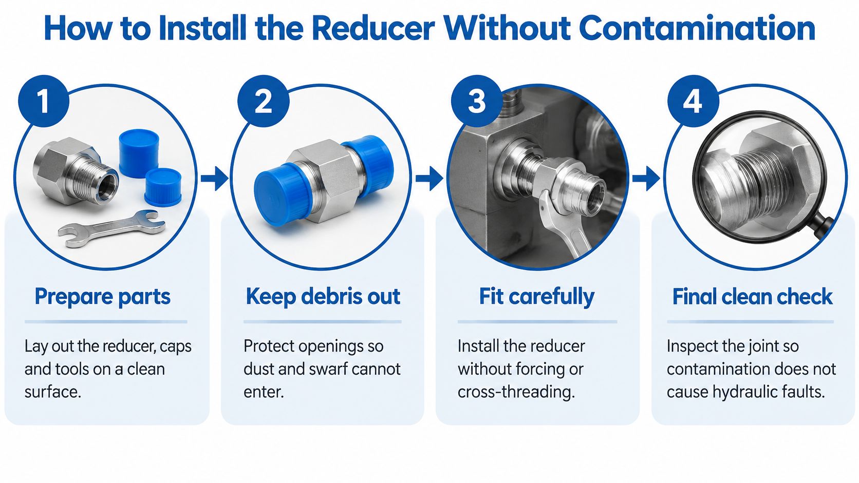
Make the machine safe. Isolate the power source, secure raised equipment and release stored pressure using the machine's procedure. Cap open ports immediately and leave the replacement fitting packaged until you're ready to install it.
-
Clean the upstream line. Flush replacement or disturbed pipework using an approved method and compatible fluid. Don't wash loose swarf downstream into a valve block and call the line clean.
-
Inspect both mating parts. Look for burrs, split sockets, flattened crests and damaged sealing faces. Clean with lint-free material, and replace damaged parts rather than dressing them while they're connected to the circuit.
-
Use the specified sealing method. Where thread sealant is approved, apply it to the male thread and keep it back from the leading thread and bore. Where the port requires a bonded seal or O-ring, fit the correct new seal instead of improvising with tape.
-
Start the thread by hand. Stop if it binds or enters crookedly. Tighten using the manufacturer's torque or assembly method, with a backing spanner where needed to prevent twisting the adjoining pipework.
The practical preparation is simple enough to organise before opening the circuit.
Fill and commission cleanly
-
Filter the fill oil. Use dedicated, clean transfer equipment and the appropriate filter. An open drum and a dirty funnel can undo careful assembly.
-
Circulate under controlled conditions. Begin at low pressure, check the filter condition and obtain a representative fluid sample. Set the acceptance target from the component manufacturers' requirements, not from what the oil looks like in a jar.
-
Release the machine only after acceptance. Resolve an unsatisfactory sample before loading the system. Keep the sample result and repair details with the maintenance record.
A planned contamination-control approach should cover storage, assembly, filling and sampling, rather than relying on the machine's filter to catch everything afterwards.
A common avoidable error is using an excessive torque setting on the smaller port and cracking a thin socket. More tightening won't improve a joint whose seal, thread or seating face is wrong.
How to Leak-Test the Joint Before Full Duty
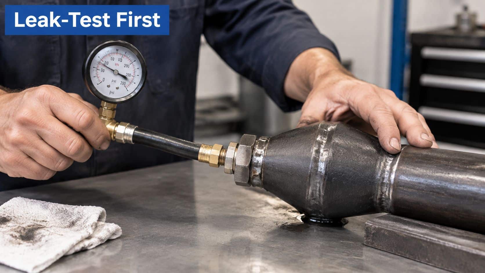
A joint can look dry immediately after assembly and weep once the oil warms. Test under a written, machine-appropriate procedure, with a competent person controlling pressure and keeping others outside the test area.
The gauge needs to show what the joint experiences, not merely pressure elsewhere in the circuit.
Use controlled stages
-
Establish a clean baseline. Clean and dry the outside of the joint, fill and bleed the circuit, and confirm that the gauge is suitable. Residual assembly oil mustn't be mistaken for a fresh leak.
-
Increase pressure progressively. Follow the equipment manufacturer's approved stages and hold times, rather than adopting arbitrary percentages. Proceed only when pressure behaviour and the joint's appearance meet the procedure.
-
Stay inside the assembly limits. Don't exceed the permitted pressure of any exposed component. Stop if pressure rises unexpectedly, the fitting moves or the assembly shows distress.
-
Inspect without touching the live joint. Use remote observation or a suitable leak-detection aid from a safe position. Never search with fingers or hold a paper towel against a pressurised fitting; a fine hydraulic jet can penetrate skin.
-
Check at normal operating temperature. Run the approved operating cycle and inspect again once temperatures stabilise. Look for fresh wetting, droplets and unexplained pressure behaviour.
-
Depressurise before correction. If the joint weeps, isolate and release pressure before investigating. Persistent leakage calls for dismantling and checking the seal, faces and threads, not repeated tightening.
The pass condition is no visible leakage and pressure behaviour within the approved test criteria. A falling gauge reading needs investigation, but temperature change and other circuit leakage can affect it, so don't diagnose the reducer from the gauge alone.
Use documented pressure-testing procedures and record fluid temperature, test conditions and results. Avoid improvised compressed-air testing; choose the approved compatible liquid and procedure for the equipment.
Use any demonstration alongside, not instead of, the machine-specific instructions.
For a separate domestic-water problem, Total Plumbing & Hot Water Systems' information on repairing leaks around your property offers relevant plumbing context. Domestic leak-finding methods aren't a substitute for hydraulic injection-risk controls.
Hydraulic and Machine Faults and Their Fixes
A new noise or change in actuator speed after fitting a reducer deserves investigation before the machine returns to work. The timing makes the repair area worth checking, but it doesn't prove that the reducer caused every symptom.
A restricted pump inlet needs particular attention. Reducing the available passage can increase suction losses and contribute to cavitation, especially with cold oil or a dirty inlet strainer.
Symptoms, likely causes and fixes after fitting a reducer
| Symptom | Likely cause | Fix |
|---|---|---|
| Cavitation noise at the pump inlet | Suction restriction from the step-down | Check suction conditions and filter condition; confirm line sizing before enlarging it |
| Erratic actuator speed | Flow restriction through the narrow bore | Measure flow, then assess a larger bore or revised routing |
| Oil running hot | Pressure drop across the restriction | Check the restriction, pump load and oil temperature together |
| Fitting cracks under pressure | Excess pressure, a lower-rated part, assembly damage or mechanical loading | Isolate, replace the damaged part and investigate ratings and loading |
| Metal debris in the filter | Possible assembly contamination or component wear | Inspect debris, flush as appropriate, replace the filter and sample against the cleanliness target |
Measure before replacing parts
For erratic movement, measure flow under the relevant load and temperature conditions. Don't condemn the pump because an actuator slowed after a pipework change. Check for a restricted passage, a displaced seal or an unsuitable adaptor before ordering major components.
For overheating, compare pressure on either side of the suspected restriction where safe test points are available. Consider duty cycle and pump loading at the same time. A hot fitting alone doesn't establish the source of the loss.
Metal in a filter needs more than a filter change. Examine the debris and check whether the system is still producing it; continued metallic contamination may indicate internal damage rather than dirt left during assembly.
A cracked fitting is a stop-work fault, not an invitation to reseal it and try again.
Exemption isn't permission to improvise
HSE guidance on the Pressure Systems Safety Regulations explains that hydraulic systems using hydraulic oil aren't covered by PSSR 2000. That distinction doesn't remove the need for competent maintenance, effective protective devices and documented safe operating limits, nor does it settle separate product-supply obligations.
For a heating-system complaint rather than a hydraulic-machine fault, Encano Plumbing & Drainage Ltd.’s explanation of why boilers keep losing pressure addresses a different diagnostic setting. Don't transfer boiler pressure assumptions to mobile or industrial hydraulic equipment.
Investigate in a sensible order: filter condition, suction line, then the disturbed joint and its surrounding pipework. Take flow and pressure readings before deciding that a larger reducer is the answer.
Ordering the Matched Reducer and Getting Help
A useful order describes the complete connection, not just the nominal transition. The supplier needs enough information to confirm that the replacement will fit, seal and carry the intended duty.
Send a concise specification with:
- Both port details: Thread standard, gender, parallel or taper form, and sealing arrangement.
- Operating conditions: Fluid designation, pressure, temperature and duty cycle.
- Installation constraints: Available clearance, orientation, pipe support and access for tightening.
- Identification evidence: Clear photographs, equipment details and any legible markings on the removed part.
- Required paperwork: Drawing, ratings, material information and applicable installation or conformity documents.
Photograph the sealing face as well as the thread. A side view of an oily fitting often hides the feature that decides which adaptor is required.
Choose the replacement around the application, then plan the clean installation and acceptance test before dispatch. If the original part has cracked, leaked repeatedly or restricted flow, describe that fault rather than asking for an identical replacement without explanation.
A matched reducer should solve the connection problem without creating another maintenance job. If the specification is incomplete, getting technical confirmation before ordering is usually quicker than dismantling the machine again after a failed fit.
MA Hydraulics Ltd offers hydraulic component selection support for mobile and industrial applications and can review your reducer's port details, fluid and operating conditions before you order. Phone 01724 279508 today, or send us a message with photographs and the connection specification so the team can help identify a suitable replacement.
