

In UK trade listings, 7.5 x 60 almost always means a 7.5 mm diameter, 60 mm long concrete or masonry screw; a shaft, pin, tube or hydraulic reading needs a drawing or part check before ordering.
But what tells you those numbers describe a fixing rather than a precision machine part? The application, head shape, surface finish and measurement convention matter more than the size label alone. Get the component family right before comparing prices or reaching for the drill.
What 7.5 x 60 Most Likely Refers To
A concrete or masonry screw is the strongest starting assumption when the dimension appears in a UK fixings catalogue. It isn't a safe assumption when the same marking comes from a maintenance sketch or a dismantled hydraulic assembly.
The Scaffolding Direct concrete screw specification identifies a 7.5 mm diameter, 60 mm long fixing with a 6.0 mm drill hole, an 8 mm fixture clearance hole, a maximum fixture thickness of 30 mm, yellow-passivated steel plating and a T30 drive. UK listings offer packs of 85 or 100, which is consistent with a standard repeat-use fixing rather than a bespoke machine component.
That combination suits light-duty work such as securing window and door frames to concrete, brick, stone and concrete block. Direct-to-substrate screws cut their own thread into suitable pre-drilled masonry, removing the separate nylon plug used with conventional plug-and-screw systems.
Likely readings of 7.5 x 60 by context
| Likely context | What the numbers measure | Typical use | How to confirm |
|---|---|---|---|
| Concrete or masonry screw (UK trade listing) | 7.5 mm diameter × 60 mm overall length | Window and door frames to concrete, brick, stone and block | Check the datasheet for pilot hole and fixture limits |
| Shaft, dowel or locating pin | 7.5 mm diameter × 60 mm length | Machined locating shafts and dowels | Check the engineering drawing and tolerance |
| Tube, pipe or hose fitting | 7.5 mm bore or outside diameter × 60 mm length | Pipe fittings and hose ends | Measure with callipers and establish whether the figure is OD or ID |
| Hydraulic rod end or clevis pin | 7.5 mm pin diameter × 60 mm pin length | Cylinder and linkage pivot pins | Check the model code and mounting drawing |
A size without context is like a shoe size without a country. The notation looks complete, but the convention needed to interpret it is missing.
The photograph gives a useful scale reference, not proof that its head style matches the countersunk product specification.
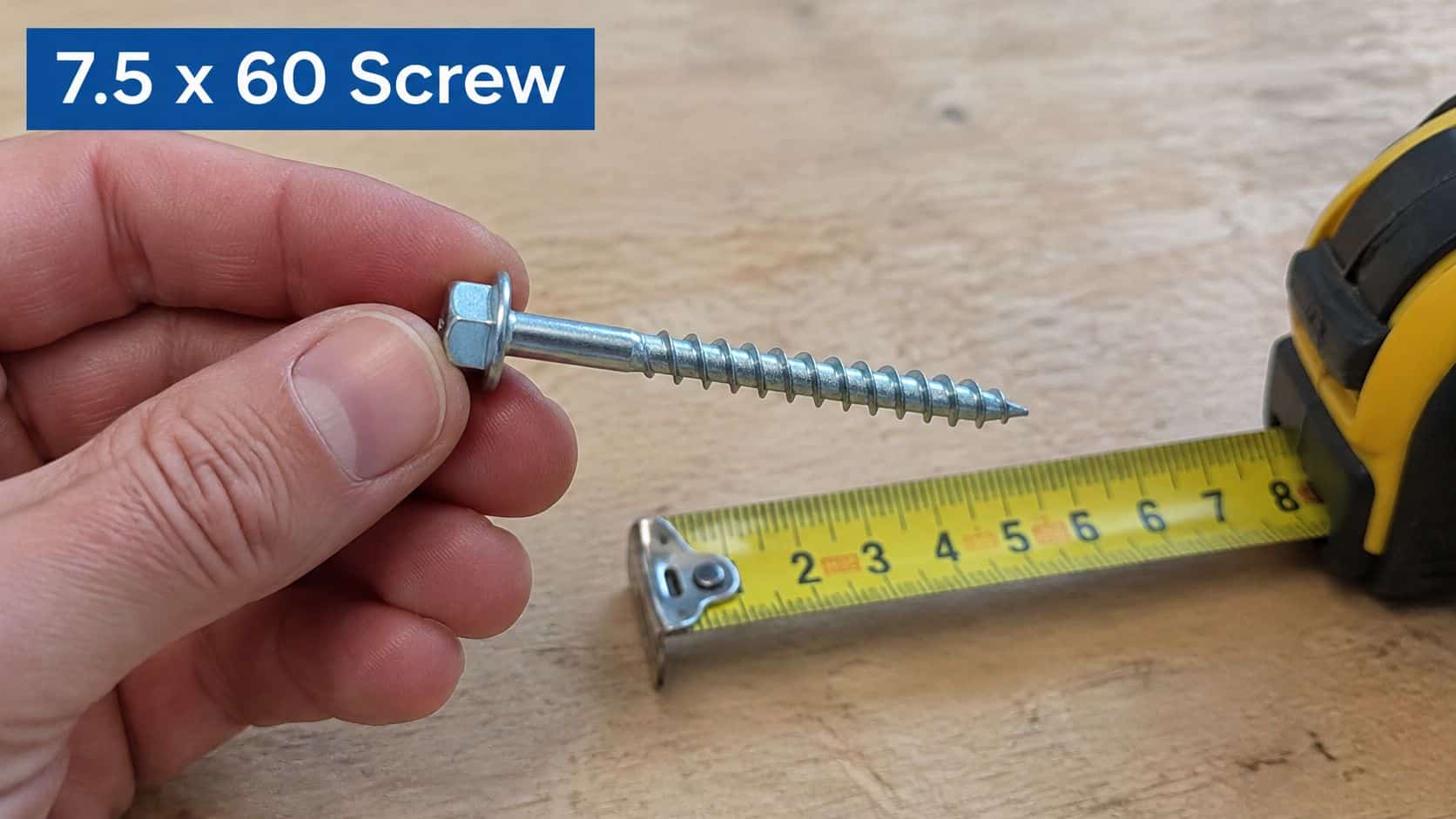
Match the part to a context row before treating any catalogue result as a replacement.
Reading the Numbers and Converting the Units
The x means by, not multiplication. For a screw or plain shaft, the first figure normally describes diameter and the second describes length; for tubing, the diameter could be internal or external.
Length also needs a datum. A countersunk screw is generally measured from the top of its head to its tip, while a projecting-head screw is normally measured from beneath the head. A shaft drawing may distinguish overall length from the length of its working journal.
Metric dimensions and imperial equivalents
The imperial equivalents below are rounded conversions for recognising an older drawing, not alternative ordering sizes.
| Metric (mm) | What it refers to |
|---|---|
| 7.5 | Screw diameter, measured over the thread crests; approximately 0.295 in |
| 60 | Overall head-to-tip length for the countersunk fixing; approximately 2.362 in |
| 6.0 | Pilot drill-hole diameter in concrete or masonry; approximately 0.236 in |
| 8 | Clearance hole diameter in the fixture; approximately 0.315 in |
| 30 | Maximum fixture thickness for the specified product; approximately 1.181 in |
Keep your working measurements in metric. Don't round a metric diameter to a convenient imperial fraction, then order the nearest-looking item: a small mismatch can change thread engagement, bearing fit or clearance.
For threaded fixings, major diameter means the diameter across the thread crests, not the narrower root between them. On a plain locating pin, the working diameter may carry a tolerance that isn't visible in the shorthand size.
Practical rule: Convert to understand an unfamiliar drawing, but order against the original dimensional system and specification.
The same discipline applies when choosing metric carriage bolts from XTREME EDEALS INC.: diameter and length are only part of the selection. Head form, thread and intended joint still need checking, and a carriage bolt isn't interchangeable with a masonry screw.
Convert an imperial measurement only when necessary, then compare it with the listed metric dimension without concealing the difference by rounding. If it falls between catalogue sizes, investigate the drawing, wear or measurement method before choosing the nearest part.
Why 60 mm Is Not the Depth That Grips
The central mistake is treating total screw length as usable anchorage. The fixture, packers, washers where applicable, and any plaster or other non-structural layer all occupy length before the screw reaches sound base material.
The TIMco concrete screw datasheet identifies the 7.5 mm × 60 mm screw, its T30 drive and a maximum fixture thickness of 30 mm, and lists concrete, solid brick, perforated brick, hollow blocks and natural stone as suitable materials. That material list isn't permission to assume identical holding performance in every wall.
Approximate grip left after the fixture
These are hypothetical subtraction examples using the nominal overall length. They estimate how much screw enters the base, not effective anchorage or permissible load.
| Fixture thickness | Approximate length in base | Practical note |
|---|---|---|
| 10 mm | About 50 mm | Thin fixture, with most of the screw entering the base |
| 20 mm | About 40 mm | Frame and packers consume more length; holding capacity still needs checking |
| 30 mm | About 30 mm | Maximum fixture thickness for this product; drilling must extend beyond embedment |
A frame with packers can look substantial and sit firmly against the wall while leaving less useful engagement than expected. Plaster, a cavity or a loose mortar bed doesn't become structural material because the screw passes through it.
The drilled hole must extend beyond the intended embedment by the manufacturer's specified allowance. Otherwise, retained dust or the screw tip can stop the fixing before the head seats, producing resistance that feels like tightening.
Establish the base before judging the fixing
Answer these questions before installation:
- What does the length describe? Establish whether the catalogue gives total screw length or a separately defined anchorage dimension.
- What remains after the fixture? Include every layer between the head seating surface and sound substrate, not just the visible frame.
- Is the substrate covered? Hollow material needs suitable supporting webs; weak masonry and cracked concrete require specific assessment and an approved fixing arrangement.
Don't assume a product suitable for hollow blocks is suitable at every position within a hollow block. Equally, an ordinary concrete designation doesn't establish approval for cracked concrete.
For engineers accustomed to metalwork, CNC threading best practices from FIRMFG offer a useful comparison for blind-hole depth planning. The shared issue is bottoming out before seating, although masonry thread formation and load assessment are different from a tapped metal joint.
Subtract the complete non-structural stack from the specified screw length, then check the remaining engagement against the manufacturer's installation requirements. If it doesn't qualify, select a different fixing rather than tightening harder.
How to Verify the Right Part Before You Order
An old part is useful evidence, but it isn't automatically a reliable master. Wear, previous substitutions and corrosion can all make a replacement copied from it wrong.
Record the identity and measurements
-
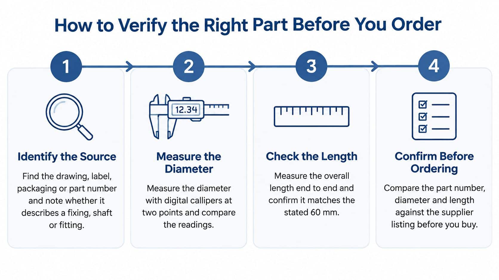
Identify the source. Find the drawing, packaging, label or part number and establish whether it describes a fixing, shaft or fitting. A handwritten stores description can omit the feature that distinguishes similar parts.
-
Measure the diameter with digital callipers. Clean the measuring surfaces, zero the tool and take readings at two positions, measuring thread crests on a screw. Record both readings before averaging them; a noticeable difference can reveal wear or taper that an average would hide.
-
Check the length datum. Measure overall length using the convention for that head style, not merely the threaded portion. For countersunk heads include the head; for projecting heads measure beneath it, unless the drawing specifies otherwise.
-
Record the drive and head style. Confirm the recess, head diameter and seating shape, with the specified T30 drive applying to the concrete screw discussed here. A hex-head photograph doesn't establish compatibility with a countersunk seat.
The infographic provides a compact identification sequence; the written checks also cover installation conditions.
Confirm the application and purchasing record
-
Identify the actual substrate. Distinguish concrete, solid brick, perforated brick, hollow block and natural stone rather than recording everything as masonry. Don't mistake a hard surface skin for sound material throughout the fixing depth.
-
Compare the complete datasheet with the listing. Check pilot diameter, fixture clearance, permitted fixture thickness, drilling requirements and plating against the exact product code. A shared nominal size doesn't establish a shared installation specification.
-
Match the coating to the environment. Treat ordinary yellow-passivated steel as a general internal-use option unless the manufacturer confirms suitability elsewhere. Exposed, persistently damp or chemically aggressive locations need a deliberately specified corrosion-resistant solution.
-
Keep a sample and a clear record. Photograph the component beside a scale, including its head, ends and markings, and retain the supplier code for reorders. For a difficult match, obtain a sample before committing to a production quantity.
For tube-mounted components, check the surrounding support arrangement too. A clamp for tubing is selected around the tube's outside diameter and installation conditions, not an unexplained bore measurement.
A photograph helps identify a component family. A drawing establishes the dimensions and interfaces you must buy.
Where the Size Turns Up in Hydraulic and Industrial Work
Away from a fixings counter, an unlabelled dimension is more plausibly a pin, shaft or spigot when it's written beside a machine component. Start with the assembly rather than searching the numbers in isolation.
Probable part by application and the check to confirm it
| Application | Probable part | Check to confirm |
|---|---|---|
| Hydraulic cylinder mounting | Clevis or pivot pin, potentially 7.5 mm × 60 mm | Pin diameter, groove position and cylinder model code |
| Gear pump or motor mounting | Locating dowel or mounting bolt | Flange standard, Group size and bolt grade |
| Power pack assembly | Pump shaft spigot or coupling | Coupling bore, keyway and pump shaft diameter |
| Mobile plant fixed to concrete | Concrete screw, potentially 7.5 mm × 60 mm | Substrate, fixture thickness and load type |
A clevis pin is recognisable by its bearing surface and retention arrangement, rather than a thread intended to cut masonry.
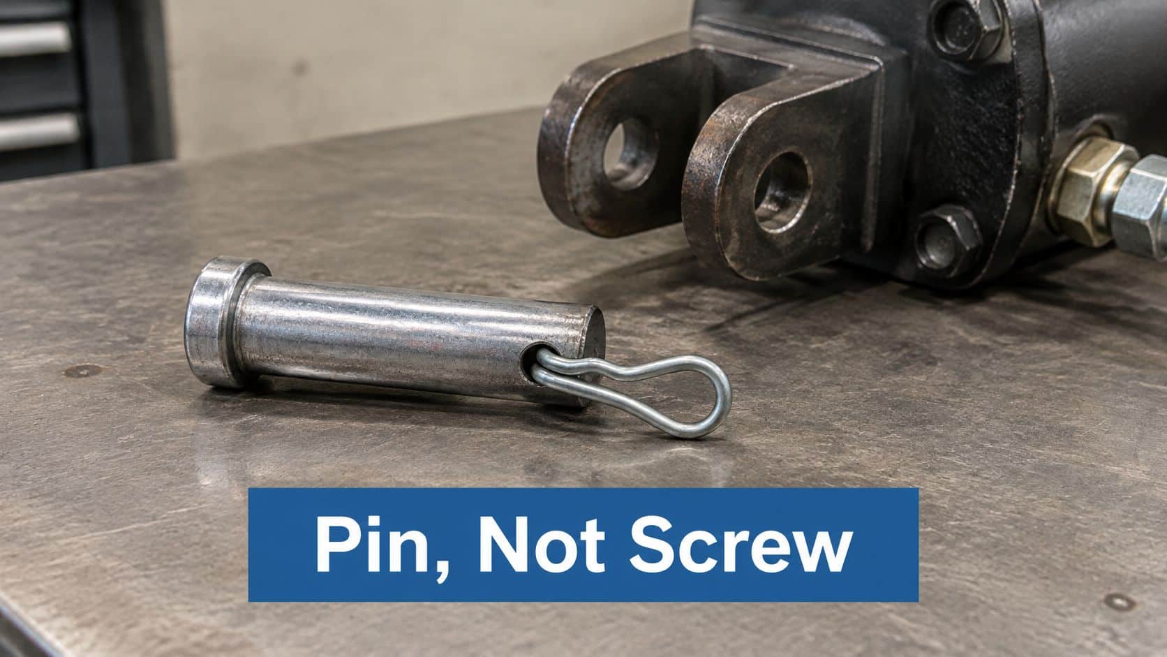
Hydraulic component identification covers a broad range of interfaces. According to the British Fluid Power Association, the UK fluid-power market was estimated at approximately £1.1 billion in 2024, with hydraulics representing about 80% of the market.
Cross-reference the assembly before the loose part
First identify the component family: gear pump, motor, cylinder, valve or power pack. Then obtain its model code or Group size and locate the relevant mounting or shaft drawing.
Only after that should you compare the loose component's diameter and length. A coupling can appear to fit yet have the wrong keyway, insufficient shaft engagement or an incompatible hub arrangement.
The same caution applies to ports. A guide to hydraulic fittings types helps distinguish connection families, but the sealing arrangement and thread identification must agree with the actual component.
The embedded video is supplementary; use the written identification checks if the player isn't available.
A matching external envelope doesn't confirm fit or function. Check flange geometry, bore, keyway, retaining features and material requirements before accepting a cross-reference.
For hard-to-find components, a model code plus a mounting drawing is usually more useful than a polished photograph of an unidentified shaft. Include the mating component where possible, because that shows which surfaces locate, transmit torque or carry pivot loads.
Common Mistakes That Make a 7.5 x 60 Part Fail
A fixing that feels tight isn't necessarily secure, and a pin that slides into a hole isn't necessarily suitable. Most selection errors come from checking the easiest dimension while ignoring the working interface.
Mistakes and their consequences
- Buying by length alone. Ignoring the fixture stack can leave inadequate engagement in sound material, even when the head seats neatly.
- Assuming every masonry base behaves alike. Unsupported hollow sections, soft material or unassessed cracked concrete can give a convincing initial fit followed by pull-out under load.
- Drilling near an edge or corner without checking limits. The fixing can split the substrate or break away its edge. Use the manufacturer's specified spacing and edge distances.
- Overtightening to correct a poor hole. Extra torque can strip the masonry thread, distort a frame or crack the fixture. Stop and establish whether the hole, substrate or fixing is wrong.
- Confusing metric and imperial dimensions. A close-looking substitute can bind, rattle or damage the mating part. Reversing diameter and length creates an entirely different purchasing error.
- Using a masonry screw as a pivot pin. Threads provide an unsuitable bearing surface for a plain pivot, encouraging wear, clearance and misalignment.
- Choosing ordinary plated steel for wet exposure. Corrosion can reduce section and seize the assembly, making future maintenance harder.
Know when dimensional matching isn't enough
On small hydraulic cylinders, mounting pins and brackets must suit the cylinder's forces and articulation. A pin that prevents the eye from moving freely can impose side loading instead of allowing the intended pivot action.
Safety boundary: A convenient size match isn't an engineering specification.
Treat this concrete screw as a light-duty fixing, not a default anchor for hydraulic equipment. Heavy, lifting or safety-critical mountings need an engineer's design and a specified component with suitable installation and load information.
Confirm the Part Before You Buy or Fit
Place the order only when the identification checks agree: component family, measured dimensions, drawing convention, material and application. Order against a datasheet or model code, not a search phrase that happens to return a similar photograph.
For masonry work, the decision depends on the actual substrate and the complete fixture stack. For a hydraulic assembly, the machine drawing and component specification take priority over a general dimensional match.
Make the enquiry easy to resolve
Send a compact identification record:
- Application and context. Explain whether the part fixes a frame, locates a pump, supports tubing or forms a cylinder pivot.
- Measurements and photographs. Include diameter, overall length, head or end details, and a clear view of identifying marks.
- Installation conditions. State substrate and fixture thickness for anchors, or mating interfaces and model code for machine parts.
If a replacement will be manufactured rather than bought from stock, specify permissible dimensional variation as well as nominal size. American Additive Manufacturing's resource on dimensional tolerances for additive manufacturing is relevant when considering a printed replacement, but its process guidance doesn't override the fit required by the original assembly.
MA Hydraulics, based in Scunthorpe, can help identify components from a photo, drawing or model code and cross-reference hard-to-find pump, motor, valve and power pack parts. Having the application and measurements ready makes that conversation more productive.
MA Hydraulics Ltd offers hydraulic component selection, replacement-part cross-referencing and bespoke power pack support, helping you distinguish a simple size match from the right working component. Visit MA Hydraulics Ltd to discuss your application. Phone 01724 279508 today, or send us a message with your measurements, model code and a photo of the part.
