
You're often at the same point when pressure testing becomes urgent. The pipework is built, the manifold is mounted, the hoses are made up, and somebody wants to energise the machine because production is waiting. That's exactly when shortcuts creep in.
In hydraulic work, pressure testing procedures are where discipline shows. A system can look well assembled on the bench and still fail once pressure loads the fittings, seals, adaptors and welded sections properly. The only useful test is one that's planned, controlled and documented. Anything else is just adding energy to a potential failure.
For UK hydraulic engineers and technicians, the job isn't to quote standards from memory. It's to turn requirements such as BS EN ISO 4413 and the wider UK pressure safety framework into a safe routine on the workshop floor or at the machine side. That means clear boundaries, the right medium, calibrated instruments, controlled pressurisation, sharp leak detection and records that stand up after the job is finished.
Why Rigorous Pressure Testing is Non-Negotiable
A hydraulic line doesn't usually give much warning before it fails under pressure. A loose cone seat, a damaged seal, a mismatched thread, or a hairline defect in a fabricated section can hold during assembly checks and then open up the moment the system reaches load. When that happens, the consequences aren't limited to oil loss and downtime. You're dealing with injection risk, moving components, contaminated work areas and a system that may no longer behave predictably.
That's why pressure testing procedures matter. They are the final proof that the design, component selection and assembly have come together as intended. A drawing can be correct. The bill of materials can be correct. The workmanship can still be wrong. Testing is the point where assumptions stop and evidence starts.
What the test really proves
A proper pressure test confirms more than whether a system leaks. It checks several things at once:
- Assembly integrity means fittings are seated correctly, adaptors are compatible, and seals are installed without damage.
- Component suitability means hoses, tubes, valves, gauges and ancillary parts are appropriate for the duty.
- Fabrication quality means welded or machined sections can withstand pressure without distortion or seepage.
- System readiness means the equipment can move into commissioning without carrying an avoidable defect forward.
Practical rule: If you find a fault during a pressure test, that's a success of the procedure, not a failure of the process. The failure would have been finding it in service.
Safety is the main reason, not compliance
Standards and site procedures matter, but the strongest reason for testing is still safety. Hydraulic oil under pressure can penetrate skin. A failed plug or temporary blank can become a projectile. A burst hose can whip with enough force to injure anyone inside the danger area. Good engineers never forget that pressure contains stored energy, even in a small test volume.
On the shop floor, the best teams treat testing as a controlled hazard. They isolate the test boundary properly, use exclusion zones, keep non-essential people away, and never place hands near suspect joints under pressure. That mindset prevents incidents far more reliably than relying on confidence or habit.
Planning Your Test Hydrostatic vs Pneumatic Methods
Pressure testing goes wrong most often before the pump is even connected. Poor planning creates most of the risk: unclear boundaries, the wrong test medium, unverified temporary fittings, or no agreed method for raising and releasing pressure. A good test starts with a written plan, however simple the job looks.
The first decision is always the same. Define exactly what is inside the test boundary, what has been isolated out, what the intended test pressure is, and who is controlling the job. If any of those points are vague, stop there.
Start with a risk assessment
A pressure test should never begin as an informal workshop task. Even on straightforward hydraulic assemblies, the team needs to identify hazards and controls before pressurisation.
Key points to settle early include:
- Test boundary so everyone knows which hoses, valves, manifolds, cylinders or fabricated sections are being loaded.
- Exclusion zone so nobody stands in line with hoses, plugs, end caps or suspect joints.
- Stored energy controls so the release path is clear and the depressurisation method is understood.
- Environmental controls so any spilled hydraulic oil or test water is contained and cleaned correctly.
- Acceptance criteria so there's no argument later about what counts as a pass, a retest or a failure.
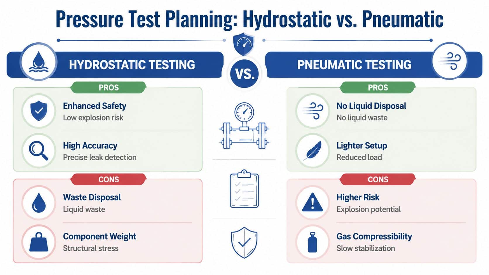
For most hydraulic systems, hydrostatic testing is the preferred method because liquid is far less compressible than gas. That lowers the stored energy in the test setup and reduces the violence of a failure. Pneumatic testing still has a place, but only where there's a sound reason and the additional risk is controlled properly.
Hydrostatic and pneumatic side by side
The comparison below reflects what works in practice on hydraulic systems.
| Criterion | Hydrostatic Testing (Water/Oil) | Pneumatic Testing (Air/Nitrogen) |
|---|---|---|
| Safety | Lower stored energy and generally safer if something fails | Higher stored energy and greater risk if a component ruptures |
| Leak visibility | Oil or water weeps are often easier to spot at joints | Small gas leaks can be harder to identify without additional methods |
| Cleanliness | May require drainage and cleaning afterwards | No liquid to drain, though gas handling still needs control |
| Suitability for hydraulics | Usually the first choice for hydraulic assemblies | Better reserved for specific cases where liquid cannot be used |
| System loading | Test fluid adds weight to the assembly | Lighter setup but more demanding safety controls |
| Stabilisation | Usually easier to achieve a steady reading | Compressibility can make pressure settling slower |
Choosing the test medium
For a hydraulic power pack, manifolded valve station, hose assembly or fabricated hydraulic pipework, hydrostatic testing usually gives the cleanest answer. You fill, vent the air thoroughly, raise pressure in a controlled way and inspect for leakage. Where contamination is a concern, clean hydraulic oil may be more appropriate than water. Where post-test drying is difficult, water can create avoidable follow-on work.
Pneumatic testing is sometimes selected where introducing liquid would damage components, create corrosion concerns, or be difficult to remove. But that choice needs stronger controls, more distance, and stricter discipline around temporary equipment. It's not the quick or casual option.
Pneumatic testing can be tidy. It is not forgiving.
Setting the test pressure
The test pressure should come from the system design basis, client specification, component limits and applicable UK requirements such as the Pressure Systems Safety Regulations 2000 where they apply. In practice, many engineers work from a test pressure above normal working pressure, often expressed as a multiple of the maximum allowable working pressure. The exact figure should be confirmed from the governing specification for the system you're testing. Don't pull a number from habit and assume it fits every assembly.
A sound planning note should record:
- Working pressure for the equipment or test section
- Target test pressure and how it was derived
- Test medium and why it was chosen
- Hold requirement from the project or internal procedure
- Relief and venting arrangement for safe completion
Assembling Your Pressure Test Equipment
A pressure test rig is only as reliable as its weakest part. That weak part is rarely the pump. More often it's a borrowed hose with an unknown rating, a gauge with no calibration record, or a blanking plug fitted because it happened to be in the drawer.
The equipment needs to be selected as a test circuit, not as a pile of loose items. Every component between the pump and the test piece must be suitable for the pressure involved and compatible with the fluid being used.
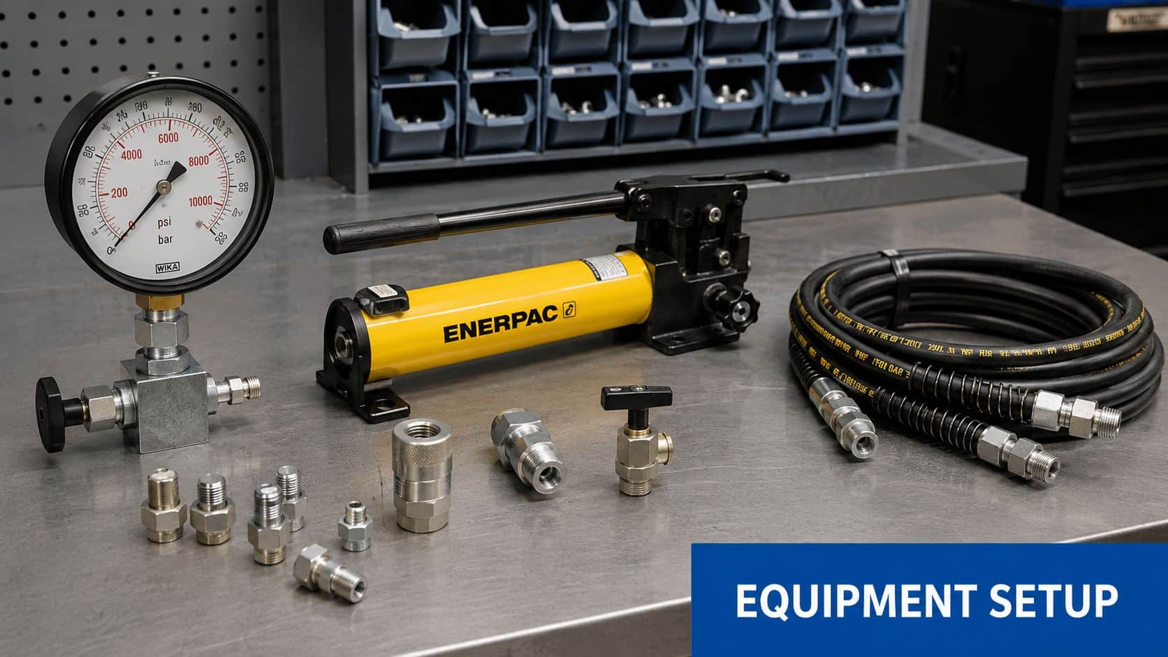
The core items you need
For most hydraulic pressure testing procedures, the rig will include the following:
- Test pump chosen for volume and control. A hand pump suits smaller circuits and gives fine control when approaching final pressure. For larger volumes, an air-driven hydraulic pump can make sense, but it still needs controlled output and a stable setup.
- Calibrated pressure gauge with a current calibration certificate and a range that allows clear reading at the target pressure without running the pointer hard against the stop.
- High-pressure hoses and fittings rated for the duty, with known condition and correct end connections. Temporary lash-ups create most workshop incidents.
- Blanking plugs, caps or flanges to isolate ports and define the test boundary securely.
- Vent points and bleed arrangements so trapped air can be removed before the main pressure rise.
- Clean test fluid appropriate to the assembly, whether that's hydraulic oil or water.
- Spill control materials because even a clean test should assume some fluid handling.
One practical option for workshop diagnostics and controlled readings is a hydraulic pressure tester kit, provided the gauges, hoses and adaptors match the pressure range and connection types in your circuit.
Most important for safety: the calibrated gauge is the truth-teller in the rig. If the gauge is wrong, every decision after that is wrong as well.
What engineers often overlook
The gauge gets attention, but the adaptors deserve the same scrutiny. A perfectly sound BSP port can be ruined by forcing an NPT fitting into it. A bonded seal can be damaged by poor face condition. A cone seat can leak because the mating surfaces were marked during handling.
Use a brief pre-assembly check:
| Item | What to check |
|---|---|
| Gauge | Calibration status, readable range, no visible damage |
| Hose | Pressure rating, abrasion, kinks, end fitting condition |
| Adaptors | Correct thread form, seal type, material condition |
| Blanking points | Mechanical security, alignment, pressure suitability |
| Pump | Smooth operation, controllable output, no external leakage |
Build the rig in a logical order
The safest arrangement is usually simple. Pump to gauge, gauge close enough to read clearly, then hose to the isolated test section. Keep the number of joints to a minimum. Each extra adaptor is another potential leak path and another place to make an error.
Support hoses so they don't twist fittings as pressure rises. Protect the gauge from direct line-of-fire positions. If the setup is awkward, change the setup. Don't accept a bad layout because it's already connected.
Executing the Test Procedure Step by Step
Execution is where calm, repeatable method matters more than speed. Most bad tests fail because pressure was applied too quickly, air wasn't bled fully, or somebody chased a leak with a spanner while the system was still live. None of that belongs in a professional hydraulic test.
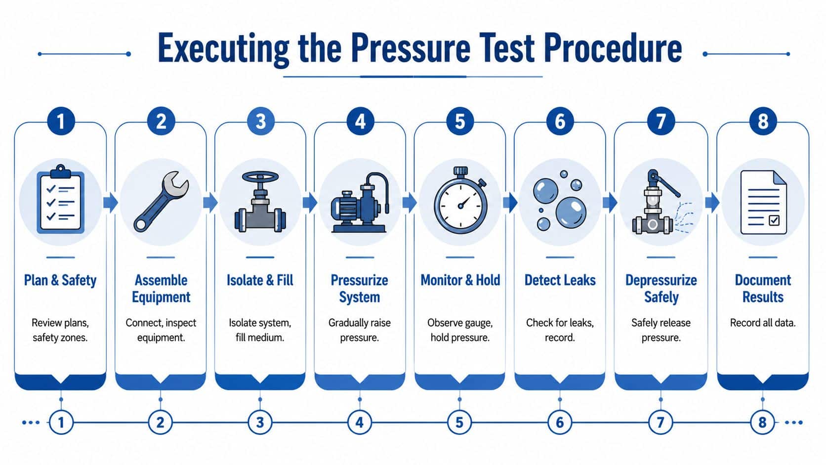
Start with a final check of isolation, temporary blanks, vent points and personnel positions. Nobody should be standing in line with hoses, plugs, adaptors or test caps when pressure is being raised.
A simple process view helps keep the sequence disciplined.
Initial low-pressure check
Fill the test section with the chosen medium and bleed all practical high points until air is removed. In hydrostatic work, trapped air is more than a nuisance. It makes readings less stable and increases stored energy unnecessarily.
Bring the pressure up only to a low preliminary level first. The point here isn't to prove the system. It's to catch setup errors, loose fittings, missing blanks and obvious leaks before they become more dangerous.
At this stage, look for:
- Sudden pressure loss that suggests a major leak or poor isolation
- External wetting around adaptors, plugs, hose ends and valve blocks
- Movement in temporary pipework that shows a support or restraint issue
- Gauge instability that can indicate trapped air or a poor instrument connection
If there's a problem, depressurise fully before touching anything. Never tighten a fitting because the leak looks minor.
If a fitting needs a spanner, it needs zero pressure first.
A practical visual demonstration can help reinforce how controlled pressure testing should be approached in the field:
Ramping to test pressure
Once the low-pressure check is clean, raise pressure in deliberate stages. Don't rush from preliminary pressure to full test pressure in one sweep. Incremental pressurisation gives the assembly time to settle and gives you time to spot problems while they're still manageable.
A staged approach usually works well:
- Intermediate hold to watch the gauge settle and inspect accessible joints
- Further pressure increase with another pause for verification
- Final rise to target only when the setup remains stable and dry
On larger systems, pressure can drift slightly as hoses expand, fluid temperature changes, or residual air compresses. That's why staged holds are useful. They separate normal settling from a genuine leak.
Holding and observing
At full test pressure, hold for the period required by the project specification, internal procedure or client standard. During the hold, the gauge should be monitored continuously or at defined intervals, depending on the formality of the test.
The observation period isn't passive. Inspect the entire accessible test boundary. That includes manifolds, valve interfaces, blank flanges, hose terminations, gauge tees and any fabricated sections. Use good lighting. If oil is the medium, a clean white rag is often the quickest way to reveal a faint weep.
Don't confuse pressure maintenance with integrity. A small trapped volume can mask a minor leak for a while. That's why visual inspection matters alongside gauge reading.
Safe depressurisation
The end of the hold is one of the highest-risk moments because people assume the job is done and move in too early. It isn't done until the system is proven to be at zero pressure and any trapped sections have been vented.
Release pressure slowly through the intended route. Watch the gauge return to zero. Then verify whether any downstream or isolated pockets may still be holding pressure. Valves, pilot-operated devices and blocked sections can trap fluid when the main gauge reads zero.
Use a simple shutdown discipline:
| Action | Why it matters |
|---|---|
| Open the release path slowly | Prevents shock loading and uncontrolled movement |
| Confirm gauge returns to zero | Verifies main test volume is relieved |
| Check trapped sections | Prevents surprises at plugs, tees or valves |
| Drain or recover test medium safely | Avoids spills and contamination |
| Disconnect only after verification | Removes the risk of residual pressure release |
The most reliable technicians treat depressurisation as carefully as pressurisation. That's usually where experience shows.
Leak Detection and Interpreting Test Results
A test result isn't just pass or fail. It's an interpretation of what the assembly is telling you under load. Some leaks are obvious. Others only appear as a dull wet ring around a fitting shoulder or a slight pressure drift that doesn't make sense until you inspect the last adaptor in the line.
Two methods matter most in hydraulic pressure testing procedures. The first is pressure stability during the hold. The second is direct visual confirmation around every accessible joint and component. Neither method should stand alone.

Reading the gauge properly
If the gauge falls during the hold, don't jump straight to the conclusion that the test piece has failed. First consider the test conditions. Fluid temperature can change. Residual air can compress and settle. Hose expansion can alter the reading early in the hold. Those effects usually stabilise. A continuing drop needs investigation.
A useful way to think about it is this:
- Stable after an initial settle often points to a sound system and normal stabilisation behaviour.
- Progressive pressure loss usually indicates an external leak, internal bypass path, or incomplete isolation.
- Erratic reading may suggest trapped air, a faulty gauge, or unstable pump isolation.
Where the duty is critical, some teams supplement direct testing with condition methods such as acoustic monitoring to investigate persistent leakage behaviour in service. That doesn't replace a proper pressure test, but it can help when faults are intermittent or difficult to localise after commissioning.
What visual inspection tells you
Visual inspection is where a technician's eye earns its keep. A dry-looking joint can still be suspect if dust has darkened around the seal line or if there's a faint meniscus under good light.
Practical methods that work well include:
- White lint-free rag wiped around fittings to reveal fresh oil immediately
- Developer spray or leak detection fluid where the medium and component finish make weeps hard to see
- Torch inspection at an angle because direct overhead lighting often hides surface wetting
- Checking underneath joints since gravity usually shows the leak path better than the top face
A pressure gauge can tell you that pressure is changing. The joint itself tells you why.
Weep, leak or failure
Not every indication means the same thing. A slight weep from a threaded fitting may point to assembly error, damaged seal faces or incorrect thread engagement. That may be recoverable after full depressurisation and strip inspection. A leak from a weld, casting, hose body or valve block is different. That is usually a hard failure of the test item, not a tightening issue.
Use this field judgement carefully:
| Observation | Likely meaning | Typical response |
|---|---|---|
| Dampness at a fitting interface | Seal issue or assembly error | Depressurise, inspect, remake correctly |
| Continuous droplet formation | Active leak path | Fail the test and repair before retest |
| Leakage from weld or body | Structural defect or damage | Remove from service and investigate fully |
| No visible leak but pressure drift | Trapped air, gauge issue, internal bypass or hidden leak | Recheck setup and isolate systematically |
Good interpretation always combines the instrument reading with what your eyes can confirm.
Documentation Common Failures and Expert Support
Once pressure is off and the rig is disconnected, the technical work still isn't finished. The record matters because it proves what was tested, how it was tested, and what result was obtained. If there's a later issue with commissioning, warranty, safety review or client sign-off, vague workshop notes won't help much.
What a proper test record should include
A pressure test certificate or report should identify the assembly clearly and show enough detail for traceability. In practical terms, that usually means:
- System identification such as machine reference, circuit name, or assembly number
- Date and technician details so the work can be traced to the person carrying it out
- Test medium and pressure applied recorded in line with the agreed procedure
- Holding period and observations including any stabilisation notes, inspection findings and remedial work
- Result stated plainly as pass, fail or retest required
Where your business works in regulated sectors, the discipline used for test records should align with wider GxP documentation requirements, especially around legibility, traceability, review and controlled changes. The same habits improve hydraulic documentation even outside formal GxP environments.
For teams managing service records, build sheets and inspection trails, a structured documentation management approach helps keep test records tied to the correct assemblies and revisions.
Common failures seen in the field
Most failed tests come back to a short list of repeat problems.
- Incorrect fitting assembly. This includes under-tightening, over-tightening, damaged seats and poor alignment. The fix is usually to strip, inspect and remake the joint properly, not to add more torque blindly.
- Incompatible threads. BSP, metric and tapered threads are still mixed up more often than they should be. If the fitting feels wrong going in, it probably is wrong.
- Damaged or incorrect seals. O-rings cut during assembly, missing bonded seals, or seal materials that don't suit the fluid will all show up under pressure.
- Poor fabrication or component defects. Cracked welds, porosity, damaged hose assemblies or flawed valve bodies need replacement or repair, not persuasion.
The useful lesson in every failed test is process improvement. If the same issue repeats, the problem usually sits upstream in component selection, hose making, thread identification, cleanliness or assembly training.
A well-run pressure test doesn't just protect the machine. It improves the next build as well.
If you need practical help with pressure testing procedures, hydraulic component selection, bespoke power packs or fault-finding support, contact MA Hydraulics Ltd. Phone 01724 279508 today, or send us a message.
