
A machine can have a correctly specified pump, a suitable valve and a well-built cylinder, yet still fail early because those parts were selected in isolation. On a UK site, the critical test is whether the complete assembly survives its duty cycle, contamination exposure, temperature changes, maintenance routine and pressure events without creating an avoidable service problem.
That is why hydraulic component design should be treated as a linked engineering discipline. The reservoir affects temperature control, the pump determines available flow, the valves influence pressure loss, the seals must tolerate the fluid and environment, and the manifold decides how efficiently the whole circuit is connected. A component that looks acceptable on a catalogue page can be the wrong choice once installation, service access and real operating conditions are considered.
Why Hydraulic Component Design Decisions Matter on UK Sites
A common failure pattern starts with a machine that appears to be operating within specification. An auxiliary pump is selected for the nominal pressure, a replacement valve matches the port size and the system runs successfully during commissioning. Months later, the machine spends longer at high load, starts in colder weather, or works with oil that is no longer clean. The pump overheats, a seal begins to bypass or a valve spool sticks. The resulting stoppage costs far more than the original component.
The problem usually isn't one defective part. It is a mismatch between design assumptions and site duty. A pump may tolerate the stated pressure but not the combination of pressure, speed, temperature and continuous operation. A cylinder may provide enough force but have seals that are poorly suited to side loading. A filter may meet its nominal rating but be difficult to reach, so technicians delay replacement.
Practical rule: Specify components around the machine's actual duty window, not the most convenient catalogue value.
The UK fluid power industry is broad enough to support specialist knowledge across manufacturing, distribution, systems design, servicing and maintenance. The British Fluid Power Association industry facts estimates that the sector employs over 15,000 people, and places the UK market at around £1.1 billion in 2024, with hydraulics representing roughly 80% of that value. The same benchmark reports that manufacturers' total UK fluid power equipment sales fell by around 10% to £1.4 billion in 2024, which reinforces the need to balance performance with availability, cost and lifecycle reliability.
Those market conditions matter at the workbench. Buyers need components that can be sourced and replaced, while designers need enough technical margin to avoid premature failure without overspecifying every part. Good hydraulic component design connects those commercial realities to pressure, flow, cleanliness, sealing, manufacturability and safe maintenance.
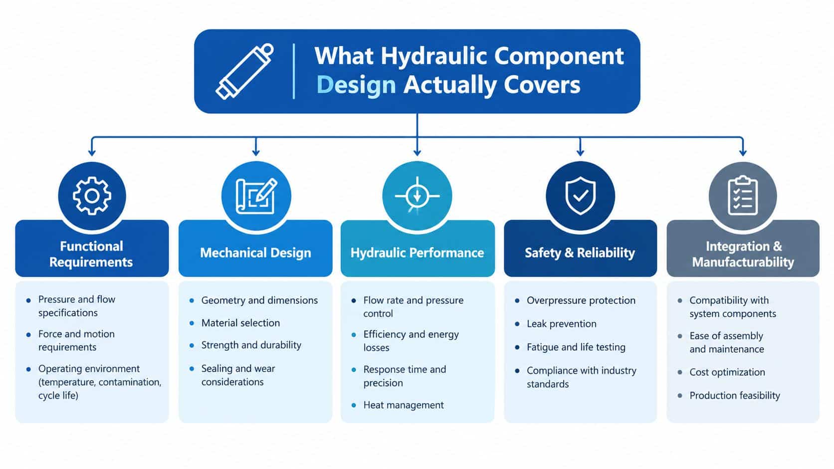
What Hydraulic Component Design Actually Covers
Hydraulic component design starts with the intended machine function and works outwards. The reservoir provides storage, deaeration and thermal capacity. The pump converts mechanical input into flow, the valves control that flow, and the actuators turn it into movement or force. Coolers, filters, hoses, fittings and manifolds must then support the same operating conditions.
That hierarchy prevents a common mistake, selecting a component before defining the system it must serve. Start by recording the load profile, movement sequence, required speed, maximum pressure, ambient conditions, fluid type, contamination risk and access requirements. Only then should the designer commit to a displacement, valve size, seal compound or manifold material.
From system targets to a manufacturable part
Hydraulic system sizing establishes targets such as required flow, pressure and actuator force. Component design turns those targets into physical parts with suitable wall thickness, ports, tolerances, surface finishes, materials and seals.
A junior designer might see a valve with the correct flow rating and assume the selection is complete. An experienced designer also asks whether the valve will see simultaneous functions, whether the pressure drop creates unwanted heat, whether the manifold can be machined and inspected, and whether a technician can remove it without dismantling half the machine.
The same thinking applies to a power pack. Reservoir volume, suction arrangement, motor cooling, filter access and relief-valve location are not separate decisions. They determine whether the pack starts reliably, runs at an acceptable temperature and can be serviced without contamination entering the circuit.
The UK guidance on hydraulic application and component selection places practical emphasis on duty pattern, environment, service access, pressure loss, replacement logic and contamination control. Those factors belong on the design record before a part number is approved.
The video below is embedded with a defined aspect ratio so the page reserves space for the player as it loads.
Core Objectives Every Hydraulic Component Design Must Meet
A workable design balances five objectives. Improving one can damage another, so the engineer has to make the trade-off visible rather than hiding it inside a component choice.
Performance means the component delivers the required pressure, flow, force and response under the intended duty. A crane outrigger cylinder, for example, needs sufficient force and controlled movement when the machine is settling, but it also needs stable behaviour when the load changes.
Efficiency concerns the losses that become heat. A pump with unnecessary leakage, a valve with excessive pressure drop or a manifold with restrictive internal passages can all increase the cooler load. Variable displacement pumps, low-leakage valves and integrated manifolds can be appropriate where the duty changes frequently, but they add specification and cost that may not be justified on a simple intermittent circuit. UK industry coverage identifies system efficiency as a significant opportunity, citing average fluid power efficiency of about 21% and a potential saving of 0.51 quadrillion Btu from a 5% improvement, alongside more than 33.95 million tonnes of CO2 in the cited analysis. These figures are reported in UK-linked fluid power industry coverage, and should be treated as context rather than a substitute for a machine-specific energy audit.
Reliability requires tolerance of contamination, pressure variation, temperature and maintenance realities. A highly efficient component that cannot tolerate the site's cleanliness regime may be a poor choice.
Safety requires risk reduction through design, guarding, control and pressure limitation. The hydraulic circuit should be assessed across all intended operating states, not only normal production.
Cost includes purchase price, installation, spares, downtime and service labour. The cheapest component wins only when it also meets the duty, cleanliness and service requirements.
| Design objective | Component-level impact | Outrigger cylinder example |
|---|---|---|
| Performance | Select bore, rod, valve capacity and pressure rating around the real load | Provide controlled force and movement during deployment and retraction |
| Efficiency | Reduce leakage, pressure drop and unnecessary throttling | Avoid restrictive valve paths that turn pump power into heat |
| Reliability | Match seals, materials and filtration to the environment | Tolerate outdoor contamination, shock loading and repeated positioning |
| Safety | Include pressure limitation, guarding and controlled failure behaviour | Prevent uncontrolled movement if the load or hose condition changes |
| Cost | Compare whole-life cost, availability and serviceability | Choose a standardised cylinder and valve arrangement where it meets the duty |
A sound design doesn't maximise one column. It gives each objective a clear acceptance criterion and records why the chosen component is appropriate.
Sizing Pumps, Motors, Valves, and Manifolds in Metric Units
The sizing process should link pressure, flow and duty cycle before the engineer chooses displacement or port size. Hydraulic power is calculated from:
P (kW) = (Q × p) / 600
Here, Q is flow in litres per minute and p is pressure in bar. The result is hydraulic power, not the electrical input required from the motor. Pump volumetric efficiency, mechanical losses, motor efficiency and transmission losses must be allowed for separately.
For a press cylinder, start with the force and movement speed. Those values establish cylinder area and flow. Pressure then establishes the hydraulic power requirement. Once the required flow is known, pump displacement follows from motor speed and the pump's real volumetric efficiency. A catalogue displacement that delivers the target only at ideal efficiency leaves no useful operating margin.
Connect the drive to the pump
Motor selection must account for peak pressure, normal pressure, acceleration, starting conditions and the expected time at load. A pump that reaches the required flow at motor speed may still overload the drive if the relief valve opens frequently or the circuit spends long periods throttling flow.
For hydraulic motors, a useful torque relationship is:
T = (V × Δp) / (2π × η)
V is displacement, Δp is pressure differential and η represents the relevant efficiency. The calculation gives a starting point. The final selection must also consider speed range, starting torque, case drain requirements, shock loads and heat rejection.
The hydraulic pumps and motors range illustrates why displacement, direction, mounting and application duty need to be considered together rather than selected from pressure alone.
Size valves and manifolds for the circuit
Valve sizing should consider flow capacity and pressure drop using the manufacturer's Kv or Cv data. Port diameter by itself doesn't prove that a valve is suitable. A valve can have a generously sized port while its internal spool, orifice or poppet creates a substantial restriction at the required flow.
Manifolds need equal attention. Keep passages direct, avoid unnecessary right-angle changes and provide sensible test points. Internal velocity should be controlled conservatively to limit noise, pressure loss and heat generation. The allowable value depends on the line function, fluid, pressure and installation, so it shouldn't be treated as a universal number.
A mobile machine may benefit from replacing an undersized gear pump with a bent-axis piston pump when the duty involves sustained pressure and variable demand. That change can reduce throttling losses, but it also introduces greater sensitivity to contamination, more demanding case-drain arrangements and a higher purchase cost. The correct decision depends on the complete duty profile, not on pump technology in isolation.
Material and Sealing Choices for Hydraulic Components
Material selection starts with the working environment, not the price list. Cast iron is often a sensible choice for durable pump bodies in demanding mobile applications. Aluminium alloy can reduce weight in equipment such as compact electric vehicles or industrial transporters, provided pressure, thread strength and fatigue requirements are suitable. Forged steel is appropriate where shock loading, high stresses or repeated pressure cycling dominate the design.
Seals need the same discipline. NBR, or Nitrile, is commonly suited to mineral oil across a broad general-purpose temperature range. FKM, often called Viton, is considered where higher temperature resistance or compatibility with synthetic fluids is required. EPDM is selected for particular fluid families such as phosphate ester fluids or brake fluid, but it isn't generally suitable for mineral oil. Polyurethane can provide strong rod-sealing and extrusion resistance in demanding applications, subject to fluid and temperature compatibility.
| Application / duty | Body material | Seal family | Key driver |
|---|---|---|---|
| Mobile pump or motor with high mechanical loading | Cast iron | NBR where compatible with the fluid | Robustness, machinability and general mineral-oil service |
| Weight-sensitive compact machine | Aluminium alloy | NBR or another compatible compound | Reduced mass, with pressure and thread strength checked |
| Repeated shock loading | Forged steel | Compound selected for the fluid and temperature | Fatigue resistance and structural strength |
| High-temperature or synthetic-fluid circuit | Steel or aluminium as structurally suitable | FKM where chemically compatible | Temperature and fluid resistance |
| Phosphate ester or brake-fluid service | Compatible steel or aluminium | EPDM where specified for the fluid | Chemical compatibility |
| High-pressure rod application | Steel cylinder body and rod | Polyurethane with suitable backup arrangement | Extrusion resistance and surface compatibility |
Seal hardness, backup rings and surface finish affect service life just as much as compound choice. Dynamic seal lands need a controlled finish, with the correct value determined by the seal supplier and motion. At higher pressure, a backup ring may be necessary to prevent extrusion, particularly where clearances increase with temperature or manufacturing tolerance.
The decision sequence is straightforward. Match the seal to the fluid first, then pressure, then temperature, and only then cost. A low-cost seal that swells in service is not economical.
For pipework and connection details, the hydraulic fittings selection guide is a useful reference point, but the final fitting still needs checking against pressure, material, installation method and maintenance access.
Reliability and Failure Modes You Can Design Out
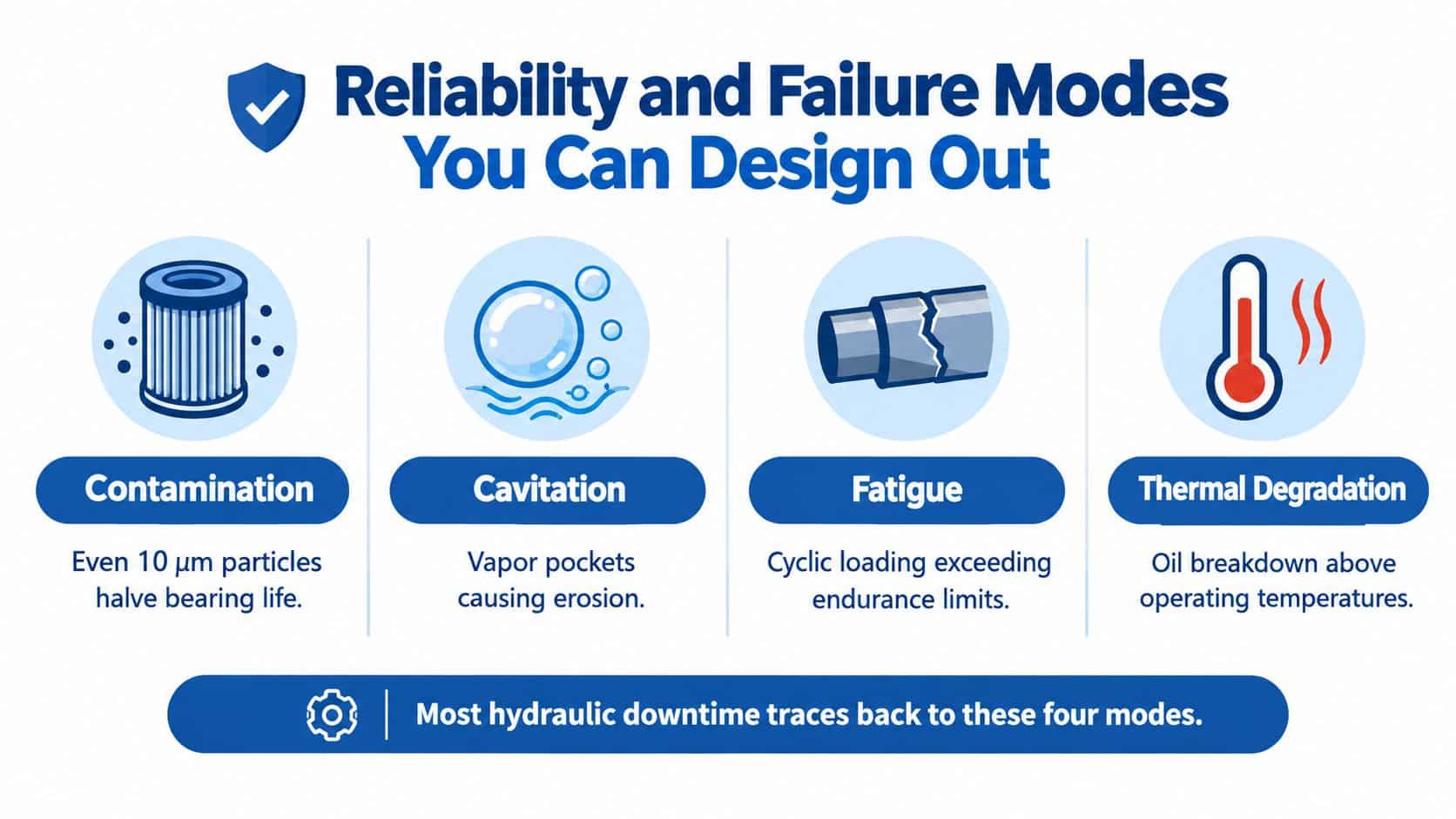
Most avoidable hydraulic failures fall into four groups: contamination, cavitation, fatigue and thermal degradation. Each leaves clues in the design stage, so the engineer should address the cause before commissioning rather than treating the damaged component as an isolated replacement.
Contamination
Particles enter during manufacture, assembly, storage, hose replacement and routine maintenance. They can damage pumps, score spools and hold poppet valves off their seats. Filtration should be selected for the component with the greatest sensitivity, with return filtration, suction protection and offline filtration used where the duty justifies them.
Filter location matters as much as filter rating. A filter that sits behind a guard or below a hot manifold may be neglected. Put service indicators where technicians can see them, provide access for sampling and specify a clean assembly procedure.
Cavitation and aeration
Cavitation occurs when the pump inlet cannot maintain the pressure required to keep the fluid in a stable liquid state. Cold, viscous oil, a restrictive suction line, a blocked strainer or poor reservoir layout can all contribute. Keep suction paths short and generously sized, minimise sharp changes and ensure the pump receives a flooded, de-aerated supply.
Aeration can create similar noise and damage while also making the system feel spongy. Reservoir return arrangements should prevent the return flow from whipping air into the fluid.
Fatigue and heat
Pressure spikes, cyclic loading and poorly supported pipework can create fatigue long before a static pressure test reveals a problem. Check hose impulse performance, clamp rigid pipework correctly and avoid forcing components into alignment during installation.
Heat accelerates oil and seal deterioration. Design the reservoir, cooler and relief circuit around the actual full-load duty, not just the pump's maximum flow. A circuit that spends most of its time bypassing through a relief valve needs a different thermal solution from one that operates intermittently at high pressure.
Finally, review each component for real-world margin. Derating is useful, but it should be based on the manufacturer's pressure, speed, temperature and life data rather than an arbitrary safety factor.
Testing, Validation, and UK Standards for Hydraulic Components
Testing should prove the design intent. A pressure test confirms structural integrity, but it doesn't prove that the component will survive repeated cycling, contamination, heat or incorrect sequencing. Separate proof and burst requirements, document the test medium and condition, and record calibrated instrument readings.
A practical validation programme can include:
- Pressure testing: Confirm that the component withstands its specified pressure regime without leakage or permanent deformation.
- Endurance testing: Reproduce the expected load sequence, speed and pressure changes rather than cycling under an unrealistically gentle condition.
- Cleanliness verification: Sample the fluid and record the cleanliness target used for the sensitive components.
- Functional testing: Check valve response, actuator movement, relief operation, leakage, noise and temperature on a controlled test bench.
- Traceability review: Retain material records, seal batches, inspection results, calibration evidence and change-control information.
BS EN ISO 4413 hydraulic compliance and verification support should be considered alongside the machine risk assessment and the manufacturer's technical file. The standard is relevant to hydraulic fluid power systems, including application rules, safe design and information for use.
UK fluid power standards guidance also identifies BS 6525 for reservoirs and BS 7388 for leak prevention and related acceptance considerations. The UK standards information for hydraulic systems safety indicates that reservoir construction and leak prevention form part of the wider engineering responsibility, not an afterthought once the pump and valves have been selected.
| Standard | Scope | Design impact |
|---|---|---|
| BS EN ISO 4413 | Hydraulic fluid power application and safety rules | Shapes risk reduction, guarding, pressure limitation, documentation and information for use |
| BS 6525 | Reservoir requirements and construction considerations | Influences tank design, internal cleanliness, access and fluid management |
| BS 7388 | Leak prevention and acceptance-related guidance | Encourages controlled inspection, sealing discipline and verification before release |
Risk assessment should follow the intended operating states, foreseeable misuse and maintenance tasks. The guidance linked to EN ISO 12100 hydraulic machinery risk assessment highlights the need to design risks out where possible and add safeguards where they remain. Pressure-limiting valves are a preferred safeguard against excess pressure, but they must be correctly located, adjusted, protected from tampering and validated during testing.
Practical Checklist and Next Steps for Your Design
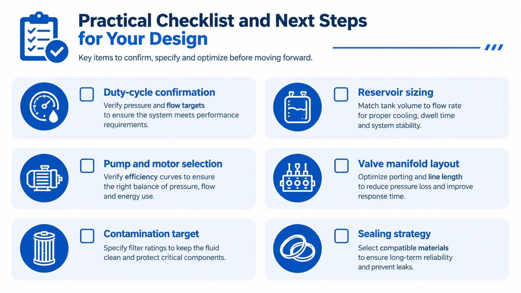
Use this checklist before releasing a drawing, ordering a replacement or approving a power-pack build:
- Confirm the duty cycle: Record pressure, flow, speed, load sequence, idle time, start-up conditions and ambient exposure.
- Size the reservoir: Allow for deaeration, thermal management, return flow behaviour, access and cleaning.
- Match pump and motor: Check displacement, speed, pressure, torque, efficiency, case drain and starting conditions together.
- Review the valve manifold: Check pressure drop, porting, test points, hose routing, service access and safe pressure limitation.
- Set the cleanliness target: Define the required oil cleanliness and provide practical filtration and sampling arrangements.
- Verify materials and seals: Confirm compatibility with fluid, pressure, temperature, motion, extrusion clearance and surface finish.
- Close the FMEA: Assign an owner to every identified failure mode and retain evidence that the design action was completed.
- Plan validation: Link each pressure, endurance, cleanliness and functional test to a specific design risk.
A useful design review pack should include the circuit diagram, component data sheets, duty profile, cleanliness requirement, pressure calculations, manifold drawing, seal compatibility checks, risk assessment and validation plan. If any of those documents is missing, the component selection is probably being made too early.
MA Hydraulics Ltd can help with hydraulic component selection, manifold design support, cross-referencing, and bespoke power-pack builds for mobile and industrial machinery. Share your duty cycle, working pressure, flow, fluid type and ambient conditions, then visit MA Hydraulics Ltd or phone 01724 279508 today, or send a message for a practical design review.
