
Most hydraulic filter selection guides begin with a micron number. That's an understandable starting point, but it's also where many poor decisions begin. A 10 µm element can underperform if its beta ratio is weak, while a finer element can create unnecessary restriction if the housing, flow capacity and cold-start viscosity haven't been assessed together.
New hydraulic oil shouldn't be treated as clean oil. UK guidance warns that unfiltered oil from bulk or drum sources can contain 2 to 20 times more particles than ISO 4406 levels acceptable for many hydraulic systems, as noted in MA Hydraulics' guidance on inline hydraulic oil filtration. The filter element is only one part of the control strategy. Fluid transfer, reservoir breathing, component wear, temperature and maintenance practice all influence whether the system stays within its cleanliness target.
This hydraulic filter selection guide uses a practical sequence: identify the most sensitive component, define its ISO 4406 cleanliness requirement, specify real filter efficiency using beta ratio, then size the housing for pressure, flow, viscosity and bypass behaviour. That approach costs more thought at the specification stage, but it avoids treating premature wear, blocked valves and repeated element changes as normal maintenance.
Rethinking Hydraulic Contamination Control
The advice to “choose the right micron rating” leaves out the part that causes many field failures. Micron size identifies the particle size associated with an element, but says little about removal consistency, dirt-holding capacity, pressure drop or bypass behaviour. A filter that appears correctly specified on paper can still allow contamination through, restrict flow during a UK cold start, or load rapidly because the incoming oil was already dirty.
Start with the condition of the fluid entering and circulating through the circuit. Contamination may arrive with new oil, enter through reservoir breathers and maintenance openings, or be generated as pumps, valves, cylinders and seals wear. Replacing a return element after a failure removes some debris, but it does not correct an uncontrolled transfer process or a breather that continually admits airborne dirt.
Practical rule: Treat every fluid transfer as a contamination risk, not as a neutral top-up operation.
Start with the fluid, not the element
Before selecting a filter, establish how oil reaches the reservoir. Bulk storage, drums and transfer equipment require their own filtration controls. Pouring oil directly from a container into a clean tank can introduce a substantial particle load before the machine completes its first operating cycle. The dirt then circulates until a filter captures it, allows it through, or reaches its bypass condition.
Record oil condition, transfer method, reservoir protection, operating environment and any recurring filter blockage. This information often explains poor element life more accurately than the nominal micron rating.
A filter cart, transfer filter or offline circuit can therefore deliver more control than fitting a finer return element. Entry-point filtration reduces the burden placed on the machine's filters, while offline cleaning can remove contamination without forcing all operating flow through a restrictive element. The correct arrangement depends on the circuit, but the objective remains the same: control contamination before it becomes wear.
The MA Hydraulics contamination-control guidance supports treating cleanliness as a management task rather than a consumables decision.
Move from reactive changes to controlled cleanliness
A reactive maintenance programme changes an element when the indicator reaches its limit, the machine becomes erratic or a component fails. A controlled programme combines particle counting, differential-pressure monitoring and disciplined oil handling to establish why the element is loading.
Rapid blockage can mean the filter is removing contamination effectively. It can also indicate dirty incoming oil, poor reservoir sealing, an undersized housing or internal component wear. Changing the element without investigating the source preserves the underlying fault and transfers the cost into repeated maintenance, lost production and premature component replacement.
Use a contamination-control workflow that asks:
- Where does contamination enter? Check oil delivery, breathers, seals, hose handling and maintenance practices.
- Where is contamination generated? Inspect for pump wear, cylinder rod damage, valve wear and debris from recent repairs.
- Which component is least tolerant? Its requirement sets the cleanliness target for the circuit.
- How is cleanliness verified? Use representative oil samples and particle counting, not visual inspection alone.
- What happens during abnormal conditions? Review cold starts, peak flow, element loading and bypass operation.
The filter specification should therefore cover the cleanliness objective, test method, beta performance, flow capacity, pressure rating, collapse resistance, seal compatibility and maintenance indicators. A sound selection also considers oil condition at entry, reservoir protection and the viscosity spike during cold operation. That turns filtration from a replacement purchase into a controlled contamination-management process.
Defining Cleanliness Targets for Sensitive Components
Filter selection starts with the component's contamination tolerance. The most sensitive component in the circuit sets the oil cleanliness target, not the least demanding component and not the filter already installed.
ISO 4406 expresses cleanliness through three numbers for particles larger than 4 µm(c), 6 µm(c) and 14 µm(c) per millilitre. The coding method is explained in MA Hydraulics' guide to ISO cleanliness codes and Parker's ISO 4406 reference material. Each number represents a particle-concentration range. For example, 11 corresponds to 10 to 20 particles/ml, 14 to 80 to 160 particles/ml, and 19 to 2,500 to 5,000 particles/ml in the relevant size band.
Set the target around the weakest tolerance
List the principal components, then identify the one with the narrowest tolerance for solid contamination. A basic gear pump or gear motor can generally operate with dirtier oil than a variable piston pump. Servo valves and hydrostatic drives usually require a substantially cleaner circuit because small clearances and control orifices leave less room for damaging particles.
A UK technical catalogue associates typical component requirements with the following targets and absolute ratings. Treat these as selection references, not replacements for the equipment manufacturer's specification.
| Component type | Target ISO code | Absolute micron rating |
|---|---|---|
| Gear pumps and gear motors | 20/18/15 | 20 µm |
| Fixed-displacement pumps and some actuators | 19/17/14 | 10 µm |
| Variable vane and variable piston pumps | 18/16/13 | 5 µm |
| Servo valves and hydrostatic drives | 16/14/11 | 3 µm |
The component relationship and rating examples appear in ISO 4406 information from the International Organization for Standardization. Choose the cleanliness level first, then select an element capable of maintaining it under real operating conditions.
Translate codes into maintenance decisions
A commonly used hydraulic baseline is ISO 4406 19/17/14, while cleaner systems may target around 16/14/11, according to MP Filtri's contamination-control material. Do not copy either code into a specification without checking component design, duty cycle, fluid type and the manufacturer's requirements.
UK operating conditions also affect whether the target remains achievable. Incoming bulk oil may already carry a high particle load, while cold-start viscosity spikes can increase pressure drop and reduce flow through the element. The target therefore needs to be considered alongside oil cleanliness at delivery, reservoir protection, filter capacity and the point at which the element is changed.
Verification must be defined as well. Particle counting shows whether the fluid is drifting outside the intended band. Differential-pressure readings show how the filter is loading and how much resistance it is adding. One measurement describes oil condition, while the other describes filter condition.
A cleanliness target is useful only when the team can measure it, maintain it and investigate movement away from it.
Over-filtering a tolerant system can add restriction and replacement cost without useful protection. Under-filtering a precision circuit can circulate wear particles through close clearances and sensitive control orifices. Set the target around the least tolerant component, then confirm that the complete filtration arrangement can hold it during cold starts, normal duty and rising incoming contamination.
Decoding Beta Ratios and Micron Ratings
A micron label without a beta ratio leaves a major gap in the specification. Two elements described with the same particle size can have very different capture performance, dirt-holding behaviour and impact on component life.
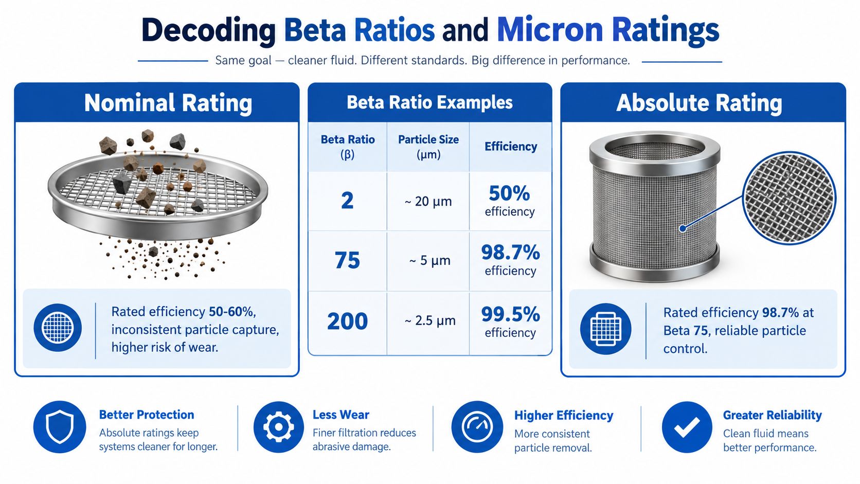
The beta ratio comes from ISO 16889 multi-pass testing. It compares the number of particles upstream of the filter with the number downstream for a stated particle size. A beta ratio of 2 means 50% efficiency, while beta 75 means 98.7% efficiency, and beta 200 means 99.5% efficiency, as shown in the required comparison visual below.
Nominal is not the same as controlled
A nominal rating describes an element's approximate ability to remove particles. It may be suitable for a general application, but it doesn't provide the same assurance as a tested beta value at a defined particle size. Procurement teams that compare only “5 µm” or “10 µm” labels can end up comparing unlike products.
Absolute ratings are more useful when the circuit has a defined cleanliness target. Even then, the data sheet should state the test method, beta value, particle size, pressure drop and flow conditions. Without those details, the word “absolute” can still be too vague for a high-value hydraulic circuit.
The Parker procedure recommends converting system severity into a media target through a weighted decision chart. It scores seven system parameters, totals the weighting and uses the resulting band to select media, rather than relying on a nominal micron label. The same method identifies beta 200, equivalent to 99.5% separation efficiency at the rated particle size, as a media performance threshold in the selection process, according to the Parker hydraulic filtration handbook.
Read the data sheet like an engineer
When reviewing an element offer, ask for:
- Beta performance: Confirm the ratio at the particle size relevant to the cleanliness target.
- Test standard: Check whether the supplier uses ISO 16889 multi-pass testing.
- Pressure-drop curve: Review clean-element resistance at the actual flow and viscosity.
- Dirt-holding capacity: Compare how much contaminant the element retains before reaching the service limit.
- Collapse rating: Confirm that the element can withstand the maximum differential pressure.
- Material compatibility: Check seals and media against the hydraulic fluid, additives and operating temperature.
A filter with a high beta ratio may impose more initial pressure drop than a coarse nominal element. That isn't automatically a problem. It becomes a problem when the housing is too small, the oil is too viscous, or the bypass setting allows contaminated oil to avoid the element.
Teams that manage several suppliers or need structured technical comparison can also use Ryken Solutions platform features to organise product information and review specification data consistently. The platform doesn't replace engineering judgement, but a consistent comparison process helps prevent a low-cost nominal element from being selected against a properly tested alternative.
Sizing for Flow and Cold Start Conditions
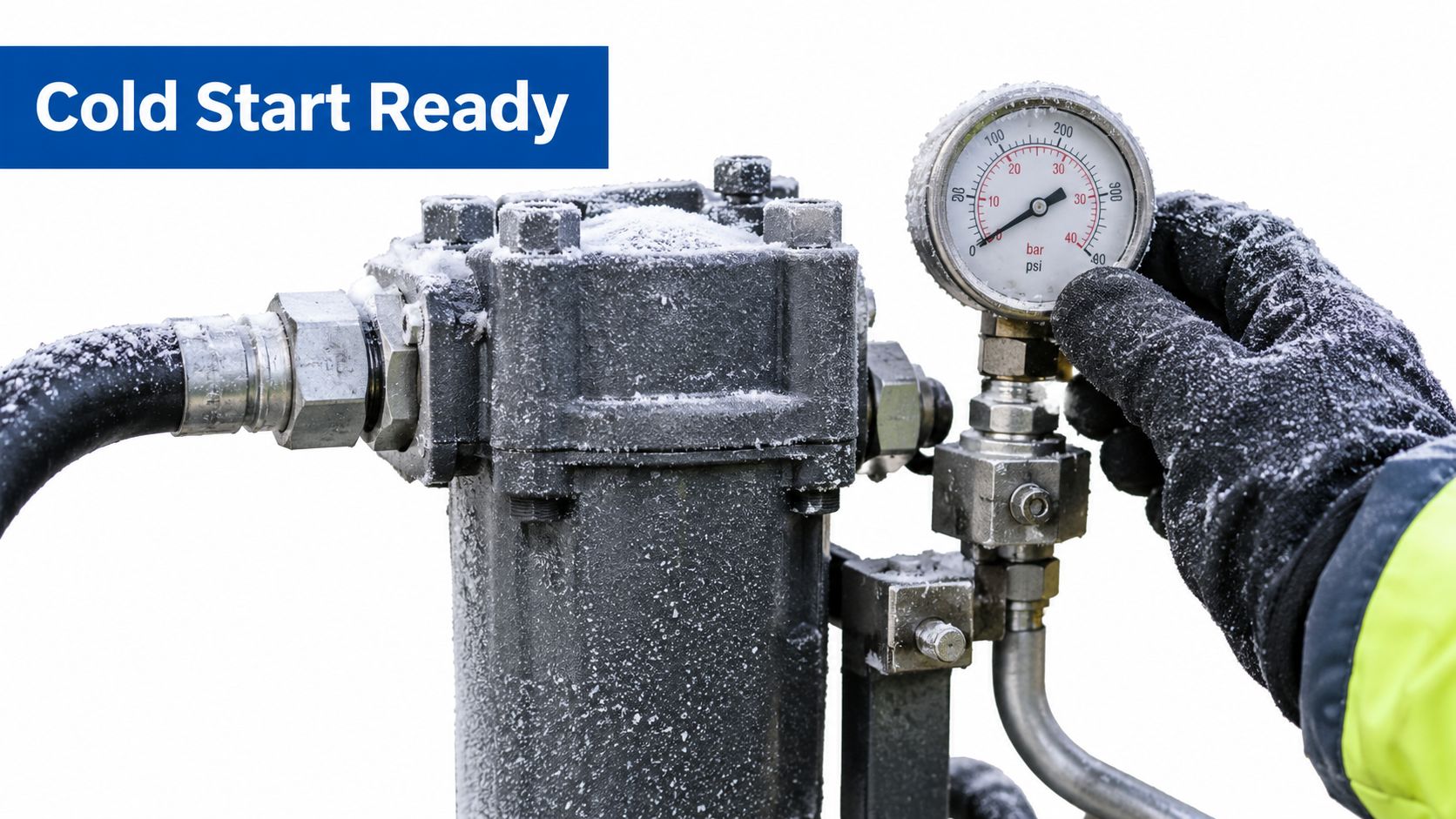
A filter that works well at operating temperature may behave very differently on a cold winter start. Hydraulic oil becomes more viscous as temperature falls, increasing resistance through the element and housing. That raises differential pressure, and the bypass valve may open before the system has reached normal working conditions.
For outdoor plant, agricultural machinery and mobile equipment, size the housing for maximum flow and cold-start viscosity, not just the flow shown in a warm-running data sheet. The manufacturer's pressure-drop curve should be checked against the actual oil grade, expected temperature and peak circuit flow.
Understand what the bypass is doing
A bypass valve protects the element and housing from excessive differential pressure, but it can also allow unfiltered oil to continue through the circuit. During a cold start, that may be preferable to element collapse, but it shouldn't be accepted as the normal operating strategy.
The critical checks are:
- Maximum flow: Include pump delivery, return surges and any transient condition that can drive flow above the normal working value.
- Cold viscosity: Use the oil supplier's viscosity data and the machine's lowest credible starting temperature.
- Clean and loaded pressure drop: Review both conditions, because a filter that starts with too much resistance has little loading margin.
- Bypass setting: Confirm when the valve opens and whether that setting is suitable for start-up behaviour.
- Element collapse resistance: Make sure the element can tolerate the maximum differential pressure if the bypass doesn't respond quickly enough.
A low bypass setting can let contaminated oil recirculate during warm-up, while an undersized filter can cause repeated bypass events. Neither issue is solved by fitting an arbitrarily finer element. The housing needs enough surface area to control pressure drop while the oil is thick and the element is partially loaded.
Winter commissioning check: Record the differential pressure from cold start through to operating temperature. A gauge that looks acceptable once warm may be hiding a bypass problem during the first part of the shift.
The following embedded video can support a visual review of hydraulic filter inspection and operating considerations. Check its frame sizing in the page template so it remains correctly proportioned on mobile and desktop screens.
Cold-start sizing also affects service intervals. If oil repeatedly bypasses while the machine warms, the element may collect contamination later, but sensitive components have already received unfiltered fluid. The maintenance team should investigate heaters, warm-up procedures, housing size and bypass selection together rather than treating the gauge as a simple replacement signal.
Choosing Element Types and Circuit Placement
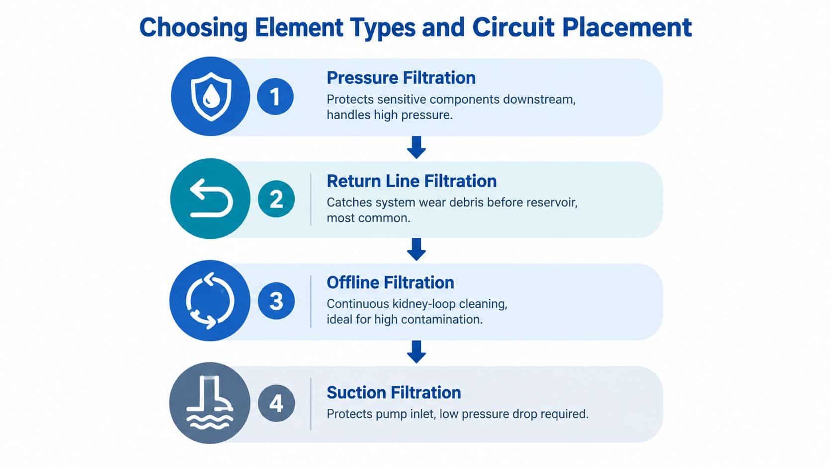
Filter placement determines which component receives protection and which contamination the element captures. A suction strainer protects the pump inlet, but it must create very little restriction. A pressure filter protects downstream valves and actuators, though its housing must withstand the circuit's working pressure. A return filter catches debris before it reaches the reservoir, while an offline circuit continuously cleans stored oil without placing the full pump flow through one element.
Match the location to the risk
Suction filtration should protect the pump from damaging larger debris while preserving inlet conditions. A fine suction element can create excessive pressure loss and contribute to cavitation, particularly when oil is cold or the reservoir level is low.
Pressure filtration is the choice when a sensitive component needs direct protection. In systems operating above 350 bar, housing strength, element collapse resistance and seal compatibility become especially important. UK guidance gives proportional valves on high-pressure systems above this level as an example where around ISO 16/14/11 may be required, depending on the application, as described in the Parker filtration product guide.
Return filtration is widely used because it captures system-generated debris before the oil reaches the tank. It still needs correct sizing. A return element that frequently opens its bypass may allow wear debris back into the reservoir, where the pump can draw it into the circuit.
Offline filtration, also called kidney-loop filtration, is useful where contamination loads are high or the main circuit cannot accept additional pressure drop. A properly designed kidney-loop filtration arrangement can clean reservoir oil independently, but it shouldn't be treated as a substitute for protecting a highly sensitive valve directly.
Consider media and supporting controls
Cellulose media can suit general applications where fluid compatibility and operating conditions are moderate. Synthetic media generally provides a more controlled option for demanding pressure, temperature or cleanliness requirements, while blended media can sit between those choices. The selection should be based on beta performance, dirt-holding capacity, pressure drop and compatibility, not on the material name alone.
Breathers deserve equal attention. A fine hydraulic element cannot maintain a cleanliness target if unfiltered air enters the reservoir during level changes. Clean transfer equipment, protected breathers and an offline circuit can reduce the load imposed on the return or pressure filter.
Avoid making one filter carry every function. The practical arrangement may combine a low-restriction suction screen, pressure filtration at a sensitive valve bank, return filtration and offline cleaning. The correct combination depends on the circuit's contamination sources and target cleanliness, but the principle remains consistent, each location should have a defined protective role.
Maintenance Intervals and Expert Support
A filter replacement interval should reflect loading, not a calendar habit. A differential-pressure indicator shows how much resistance the element is creating, while particle counting shows whether the oil remains within the required ISO 4406 target. Used together, those measurements tell the maintenance team whether the filter is loading normally, bypassing, or facing an unusual contamination source.
Take samples from a consistent point and under consistent conditions. A sample drawn from a dirty container or after a long period of settlement can produce a misleading result. Record the machine, oil type, operating temperature, filter condition, differential pressure and recent maintenance activity alongside the particle count.
Build a maintenance record that explains change
When an element reaches its service limit, inspect it rather than discarding it immediately. The captured material can indicate whether the system is receiving environmental dirt, generating metallic wear debris, or shedding seal and hose material. A sudden change in debris type is a reason to investigate pumps, actuators, valves and recent repairs.
Use the following record fields:
- Particle count: Track movement against the component-based ISO cleanliness target.
- Differential pressure: Compare cold-start and warm-running readings.
- Element condition: Note whether loading is even, localised or accompanied by collapse.
- Fluid handling: Record top-ups, transfers and any unfiltered additions.
- Component work: Link changes to pump replacements, hose failures and cylinder repairs.
Replacement parts also need to be compatible beyond their outside dimensions. The British Fluid Power Association standards library includes BS 6275-2:1984, covering hydraulic filter elements and test methods for structural integrity, and BS 6275-3:1988, covering marking. The BFPA published standards library shows why structural testing and identification matter when sourcing compatible parts for regulated industrial and mobile applications.
A UK specialist can help where a catalogue cross-reference is unclear, a replacement element has unusual seals or dimensions, or a power pack needs filtration integrated into its design. MA Hydraulics Ltd supplies hydraulic filters and components, supports cross-referencing, and assembles bespoke power solutions for mobile and industrial applications. That kind of application support is useful when the selection involves more than matching a part number.
MA Hydraulics Ltd can help you select filters by cleanliness target, beta performance, flow, pressure, cold-start viscosity and circuit placement, whether you need a replacement element, hard-to-find cross-reference or bespoke power-pack support. Visit MA Hydraulics Ltd to discuss your system, phone 01724 279508 today, or send MA Hydraulics a message with the equipment and filtration details.
