
A hydraulic system can look clean, sound normal and still be moving towards failure. That's why a preventive maintenance checklist matters. It turns scattered visual checks into a repeatable programme that technicians can execute, review and improve across pumps, motors, valves, hoses and power packs.
A practical cadence starts with daily visual and temperature observations, followed by weekly leakage, hose and seal checks. Monthly reviews should cover filters, coolers and connections, while quarterly checks can include fluid analysis, performance testing, alignment and accumulator condition where the asset's risk justifies it. Annual work should include pressure verification, gauge checks, hose testing, manifold cleanliness and safety reviews.
Every intervention begins with isolation. Hydraulic pressure and accumulator charge can remain stored after a pump stops, so isolate electrical, mechanical and hydraulic energy, secure moving parts, release pressure using the approved procedure and verify zero energy before loosening a connection. HSE guidance says work equipment should remain safe and should be isolated from energy sources where reasonably practicable during maintenance (HSE maintenance guidance).
Good records then reveal patterns. A rising temperature trend points towards inefficiency or cooling problems. Repeated filter restriction suggests contamination. New leakage can indicate seal degradation, hose damage or pressure instability, while vibration may lead you towards coupling misalignment or pump wear. UK maintenance benchmarking published in 2025 puts schedule compliance at 68%, below an 85% best-practice benchmark, and reports that 47% of companies regularly defer preventive maintenance (UK maintenance benchmarking report). MA Hydraulics Ltd can support UK operators with replacement components, cross-references and bespoke power solutions when inspection findings become planned work.
1. Hydraulic Fluid Analysis and Condition Monitoring
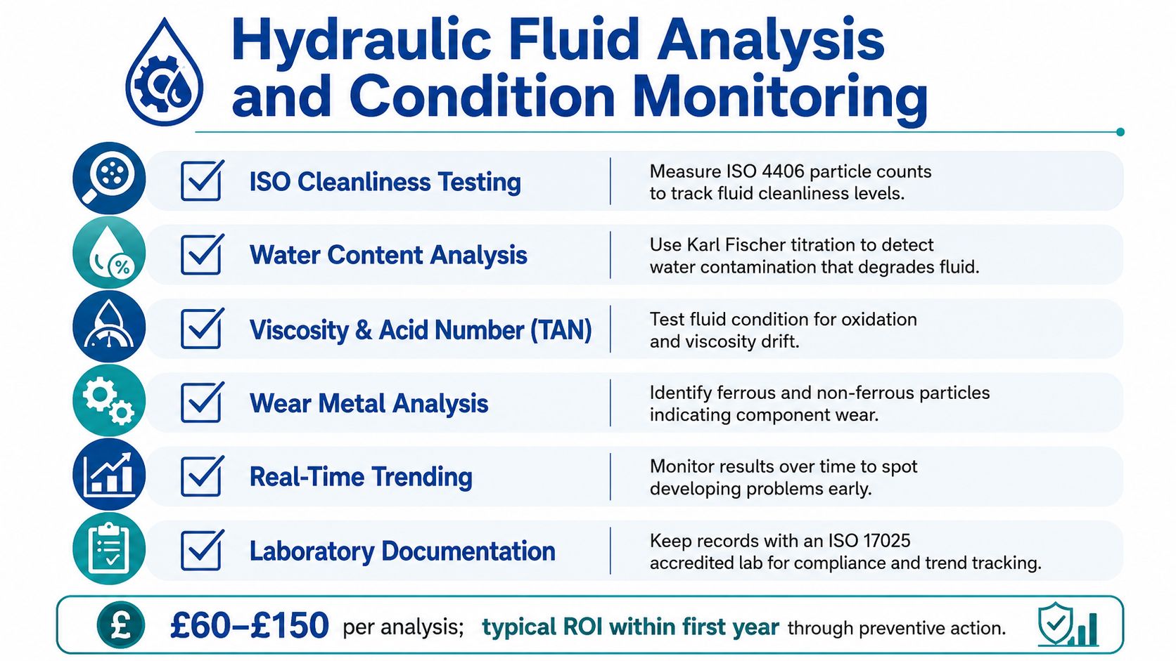
Fluid analysis is one of the least disruptive ways to understand what's happening inside a hydraulic circuit. A correctly collected sample can reveal contamination, oxidation, viscosity change and wear particles before a pump, motor or valve shows an obvious external symptom.
Start by establishing a baseline when the system is new, newly rebuilt or known to be healthy. Take samples from a consistent point, preferably the return line while the system is operating under normal conditions. Sampling from the wrong location, using a dirty bottle or changing the procedure between visits makes trend comparison unreliable.
For industrial and mobile equipment, set the interval according to duty, criticality, operating environment and the OEM's instructions. Quarterly or twice-yearly analysis may be appropriate for important equipment, but a dusty mobile machine, heavily loaded power pack or asset with a history of contamination may need closer monitoring.
Record the result, not just the sample
A useful log should identify the asset, fluid type, operating hours, sample point, date, laboratory report reference and action taken. Use a laboratory that provides recognised testing and can explain the result in relation to the fluid and equipment, rather than filing a report without interpretation.
- Check contamination: Review particle, water and dirt findings against the fluid and component cleanliness requirements.
- Review viscosity: A change can indicate fluid degradation, incorrect fluid, contamination or thermal stress.
- Inspect wear evidence: Metallic or non-metallic particles can help direct follow-up checks towards pumps, motors, cylinders or valves.
- Create a work order: Poor results should trigger filtration, fluid replacement, source investigation or component inspection.
Practical rule: A poor analysis result is a decision point, not a filing exercise. Delaying the recommended action can allow contamination or degradation to circulate through precision components.
For a structured service route, use hydraulic oil analysis support from MA Hydraulics and attach the report to the asset history.
2. Hydraulic Filter Replacement and Bypass Valve Inspection
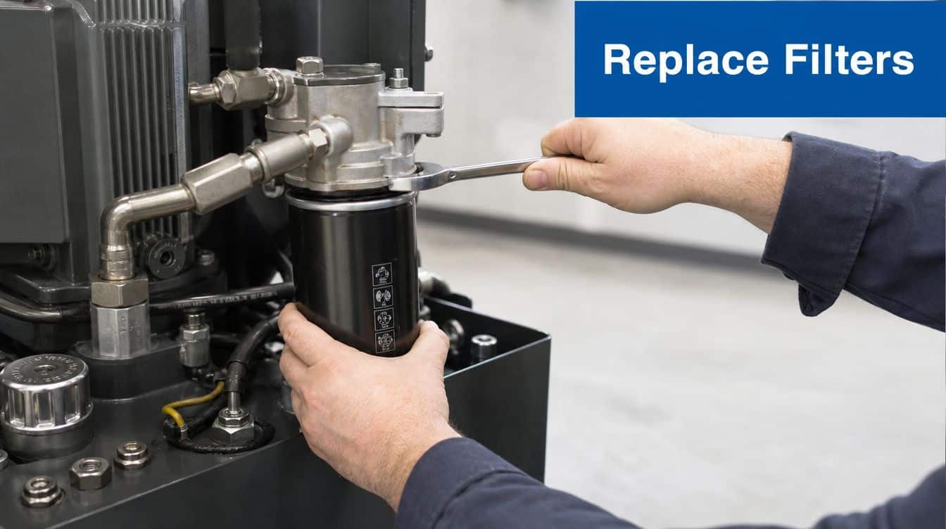
A bypass valve that opens at the wrong pressure can turn a filter into an uncontrolled contamination route. Test the valve at its specified setting, using suitable calibrated equipment, before treating the filter assembly as serviceable. Failure to open can create excessive restriction, while early or continuous opening allows unfiltered fluid to reach pumps, motors and valves.
Start with the restriction reading. Record differential pressure across each suction, return and high-pressure filter, then compare it with the manufacturer's limit and the normal reading for that asset. A rising value indicates restriction, but a sudden change can also point to a blocked breather, incorrect element or cold, high-viscosity fluid. Investigate the cause before resetting the bypass valve or replacing parts.
Build the filter task around the record
List every filtration point in the circuit. For each one, record the approved element identity, micron rating, seal material, flow direction, installation date, operating hours and differential pressure. The finest available element is not automatically suitable. Excessive restriction can reduce flow and create suction problems, while an element that is too coarse may provide inadequate component protection.
Use a clean tray to inspect the removed element and filter bowl. Sludge, fibres, metallic debris or unusual discolouration require contamination investigation and, where appropriate, fluid analysis. A replacement cartridge alone may leave the source of the debris in service.
- Confirm the element: Match the filter type, rating, seals and flow direction with the equipment specification.
- Check the bypass path: Verify cracking and reseating behaviour against the manufacturer's setting with calibrated test equipment.
- Prevent assembly faults: Clean the housing, cap and sealing surfaces, and compare the old and new elements before fitting.
- Control future response: Mark filter locations clearly and keep approved cartridges available to prevent prolonged reactive work.
- Close the record: Enter the element identity, date, operating hours, differential pressure and any debris found.
A digital maintenance record helps link repeated restriction readings, contamination findings and missed changes to the affected asset. Record the bypass test result with the filter change rather than filing it separately.
3. Seal and Gasket Condition Assessment
Seal condition affects both fluid retention and circuit cleanliness. Inspect the points most likely to fail first: cylinder rods, valve interfaces, pump shafts, motor housings, manifold joints, filter covers and reservoir fittings. A clean surface gives a reliable starting point, so remove old residue before judging a fresh leak.
Set inspection frequency from duty and history. High-use systems normally need weekly checks, while lower-duty equipment can be reviewed monthly. Change that interval after repeated failures, abnormal fluid loss or contamination findings.
Use a torch, inspection mirror, clean wipes and the equipment service record. Classify what you find rather than writing “oil present”. Record the exact location and identify staining, a slow drip, a running leak or spray. A high-pressure spray requires immediate isolation and controlled investigation. Never test a suspected leak with your hand, since hydraulic fluid can penetrate skin even through a small opening.
Select the seal for the application
An O-ring with matching dimensions may still fail if its material, pressure rating or temperature range is wrong. Check the seal compound against the hydraulic fluid, particularly where synthetic or bio-hydraulic fluids replace conventional mineral oil. Confirm the component specification and installation method before ordering parts.
During inspection or overhaul:
- Inspect for hardening: Replace brittle, flattened or cracked seals.
- Check the mating surface: Rod scoring, shaft damage and corrosion can destroy a replacement seal quickly.
- Replace matched seals: Follow the design and OEM procedure when associated seals must be renewed together.
- Protect cleanliness: Keep replacement seals covered and clean the groove before fitting.
- Prioritise by risk: Accelerate action where leakage threatens hot surfaces, electrical equipment, walkways or pressure-sensitive components.
A repeat failure needs a cause recorded alongside the replacement part. Check excessive pressure, side loading, misalignment, heat, contamination and incorrect assembly. Compare the failure pattern with pressure, temperature and service records, then decide whether to replace the seal, correct the operating condition or remove the component for controlled examination. Close the work order with the seal material, location, observed condition, corrective action and follow-up date.
4. Hose and Connection Inspection and Pressure Testing
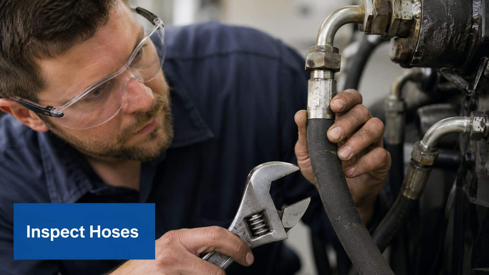
A hose can look serviceable at rest and fail once pressure, movement or heat exposes its weakness. Inspect the complete route during safe operation where practical, keeping hands clear of suspected pinhole leaks. Hydraulic fluid can penetrate skin, so isolate, depressurise and verify zero stored pressure before handling a damaged assembly.
Start at the source and follow the hose to its actuator or valve. Check for exposed reinforcement, crushed sections, blistering, flattened bends, cover cracking, heat damage, corrosion and contact with sharp edges. Watch for rubbing, excessive movement and leakage during cycling. Confirm clamps, guards and sleeves control movement without creating pinch points or restricting the bend radius.
Collision, crushing or unexplained swelling changes the decision. A hose struck, pulled or compressed may have internal damage without an external split. Isolate the equipment and arrange replacement or controlled testing by a competent person after sudden pressure loss, impact damage or visible swelling. Testing must match the hose maker's procedure, approved test medium and exclusion requirements. Use controlled hydraulic pressure-testing guidance from MA Hydraulics when planning that work.
Select assemblies against the complete duty, not the hose grade alone. Where specified, EN 856 4SP or EN 856 4SH may suit industrial high-pressure service. Confirm working pressure, temperature, fluid compatibility, impulse duty, minimum bend radius and end-fittings against the equipment requirements.
Use the inspection findings to set the action:
- Check fittings: Examine JIC, NPT and other connections for thread damage, cracks, movement and leakage.
- Verify torque: Apply the manufacturer's value with a calibrated torque wrench. Tightening by feel can damage threads or leave a joint loose.
- Check routing: Compare the installed path with the approved arrangement, including bend radius, clearance and support.
- Protect exposure points: Fit sleeves or guards, or reroute the hose, where heat and abrasion remain present.
- Record the assembly: Log hose identity, length, end configuration, installation date, defect, test result and replacement reason.
5. Pump and Motor Performance Testing
A pump or motor may keep running while its output deteriorates. Reduced flow, internal leakage, unusual noise, unstable pressure and higher temperature can appear before failure. A checklist that records only “running” or “not running” will miss these changes.
Use commissioning results as the reference point. At a repeatable test condition, record flow, pressure, speed, load, fluid temperature and noise with calibrated instruments. Repeat the same measurements under equivalent conditions. Different speed, temperature or load can make a healthy unit appear faulty, or conceal deterioration.
Test against a defined operating condition
Confirm the test arrangement, instrument calibration and acceptance range before starting. Compare flow with the approved specification and baseline. Verify that the circuit reaches its required pressure without abnormal creep or instability. Measure noise from the same position and listen under the same operating condition.
Temperature adds context. A rising outlet or case temperature may indicate falling efficiency, internal leakage or excessive restriction. Check coupling condition, alignment, mounting security and shaft movement before blaming the pump or motor.
Use the symptom pattern to set the next inspection:
- Flow falls gradually: Check internal wear, leakage and drive condition.
- Flow or pressure changes suddenly: Inspect for component damage, contamination, a failed coupling or a relief valve problem.
- Noise increases: Check bearings, cavitation, aeration, inlet conditions and alignment.
- Readings drift outside range: Raise a planned investigation, preserve the readings and record the operating conditions.
Do not authorise pump replacement from noise or pressure alone. A worn pump can still reach pressure while delivering inadequate flow, producing heat and increasing the load on other components. Trace the surrounding circuit before removing the unit.
Test critical systems more often than moderate-use assets. A pump serving several dependent functions can affect production, cylinder movement, valve response and motor speed when its performance declines. Record the trend, test equipment, readings, comparison baseline, fault hypothesis and follow-up action so the next technician can reproduce the check.
Apply OEM limits wherever provided. If no limit exists, obtain an approved engineering acceptance range from commissioning data, application requirements and competent technical assessment. A result outside that range should trigger troubleshooting, not an automatic component change.
6. Pressure Relief Valve Function and Cracking Pressure Verification
A relief valve protects the hydraulic circuit from excessive pressure. It should remain closed during normal operation and open at its specified setting. Drift, contaminated pilot passages or an insecure adjustment can cause overheating, unstable pressure or inadequate protection.
Test it with pump flow and operating conditions that represent service. A static check may miss response problems that appear under flow. Use a calibrated pressure gauge and suitable test equipment, recording the gauge calibration status with the result.
Before connecting the test equipment, confirm the valve identity, circuit diagram, maximum system pressure, intended setting and adjustment security. Inspect pilot drains and external control lines for blockage, damage or incorrect connection. A restricted pilot drain can delay or alter valve response.
Set the decision rules before testing
Record cracking pressure, reseating behaviour, pressure stability and visible leakage. Compare each result with the manufacturer's specification and the site-approved tolerance. Poor machine performance is not evidence that the relief valve needs adjustment. Check the filter, pump, gauge, circuit connection and downstream restrictions first.
Use this sequence at the test point:
- Verify the gauge: Compare it with a calibrated reference, rather than relying on an unverified panel gauge.
- Control adjustment: Only an authorised, competent person should alter the setting. Record the original and final values.
- Inspect contamination: Remove and clean the valve only under the approved isolation and cleanliness procedure.
- Check pilot circuits: Confirm drain and control paths are clear and correctly connected.
- Review the result: If cracking or reseating remains outside tolerance, isolate the fault, raise a repair decision and retain the readings for comparison after corrective work.
Do not leave a changed setting undocumented. The maintenance record should include test conditions, pump flow where measured, gauge identity, before-and-after readings, adjustment details, leakage observations, fault hypothesis and responsible person.
HSE's work-equipment guidance calls for inspection after installation and before first use, after reassembly at a new site or location, at suitable intervals, and after exceptional circumstances such as major modification or suspected serious damage (HSE inspection requirements). Add these event triggers to the digital checklist, alongside the planned frequency, instead of relying only on calendar reminders.
7. Temperature Monitoring and Thermal System Analysis
Temperature trends provide an early warning of hydraulic inefficiency. Compare readings with load, ambient conditions, operating location and an established baseline before deciding on corrective work. Rising heat can indicate internal pump or motor leakage, a relief valve passing continuously, restricted cooling, blocked cooler fins, fan failure or an undersized heat exchanger.
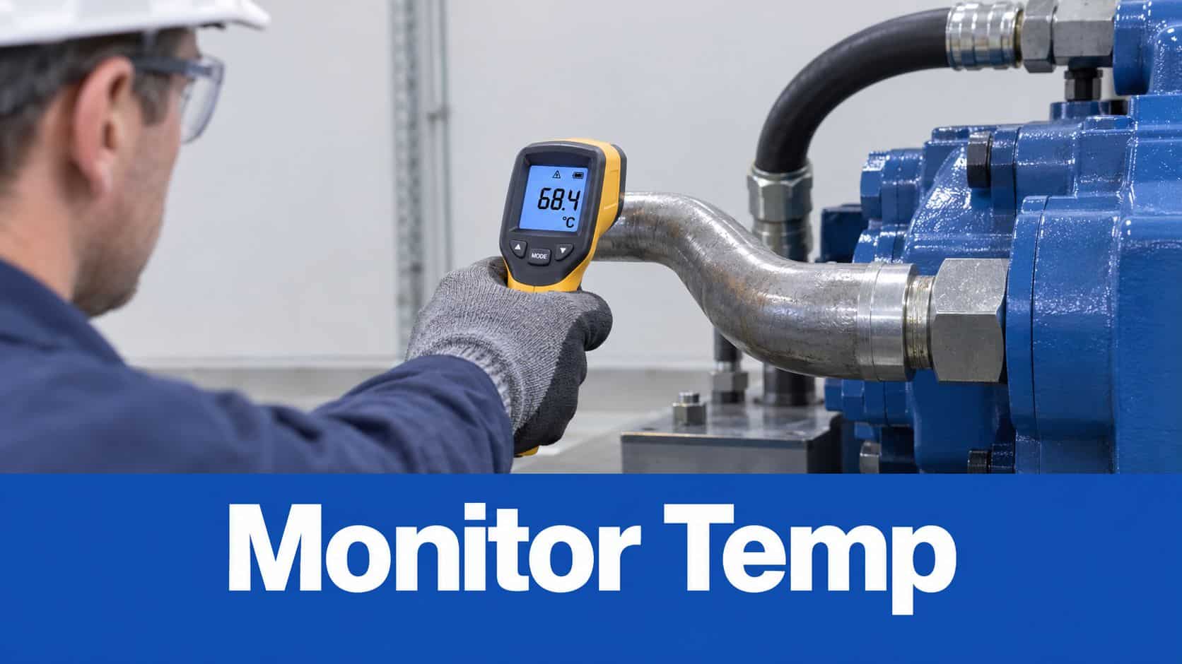
Use permanent sensors at the pump outlet and return manifold where the design permits. For portable checks, use a calibrated contact probe or infrared thermometer. Infrared readings depend on emissivity, distance and line of sight, so keep the method consistent and confirm unexpected results with an independent instrument.
For important assets, record daily minimum and maximum temperatures. Build baseline values during representative operation at different loads and in different seasons. Log ambient temperature and machine load with each reading, because a summer result cannot be compared directly with a winter result without that context.
Inspect the complete heat path
Schedule monthly cooler checks. Inspect fin cleanliness, fan operation, guards, airflow, hoses, relevant electrical supply and signs of oil-side restriction. Clean the core without bending fins or forcing contamination further into the cooler.
Use the readings to direct the fault-finding:
- Compare locations: A substantial difference between pump outlet and return temperatures can indicate where heat is generated.
- Record operating conditions: Note load, cycle pattern, ambient temperature and fan status beside every measurement.
- Trend the results: A gradual increase warrants planned diagnosis before fluid and seals deteriorate.
- Verify the sensor: Compare a suspect sensor with a calibrated independent instrument.
- Examine the relief circuit: Persistent heat under normal mechanical loading can indicate relief valve leakage.
If temperatures rise, check cooler airflow and fan operation first, then review relief-valve leakage, pump or motor efficiency and hydraulic restrictions. Record the readings, instrument identity, operating conditions and action taken in the maintenance system.
An infrared thermometer supports a quick field check, but a significant trend still requires a correctly installed sensor or hydraulic performance test.
8. Manifold and Component Block Cleanliness Inspection
A manifold can look clean while contamination remains inside its passages. Particles, varnish and corrosion may restrict small orifices, make proportional valves stick, or increase pressure drop across a section. Treat cleanliness as an internal inspection task, not an external visual check.
Set the inspection frequency from asset criticality, contamination exposure and service history. For dusty or contaminated service, an annual borescope inspection may be appropriate if the access point and method are clean. Use the same access points for comparable swab samples where practical, and store photographs with the asset record.
Record deposits, sludge, corrosion, damaged seals, blocked orifices and scoring around valve cavities. Compare the findings with fluid-condition results, temperature history, cooler performance and filter records. A clean manifold will not stay clean if the contamination source remains.
Clean without recontaminating the circuit
Choose the cleaning method from the contaminant and the manufacturer's procedure. Chemical flushing can remove varnish, but confirm compatibility with the hydraulic fluid, seals, hoses and component materials. Mechanical cleaning can remove loose debris while leaving deposits in passages, so inspect again before reassembly.
Use the following acceptance checks:
- Set a cleanliness requirement: Apply the approved ISO cleanliness target for the machine and its most sensitive components.
- Protect precision cavities: Handle proportional valves and small orifices with controlled, clean tooling.
- Replace filtration after cleaning: Fit new elements if recommissioning debris could load the existing filters.
- Confirm fluid condition: Replace or filter the fluid according to the contamination assessment.
- Verify operation: Measure pressure drop, valve response and temperature, then check for leakage after reassembly.
- Document before and after: Record the findings, cleaning method, filters, fluid condition and test results.
If pressure drop or valve response remains outside the required condition, stop repeated cleaning attempts and investigate the upstream contamination source or component damage. The short video below demonstrates a component-focused inspection suitable for technician training.
9. Coupling and Driveshaft Alignment Verification
Alignment errors can transmit torque while imposing damaging radial and angular loads on the pump or motor. Typical symptoms include vibration, noise, rising bearing temperature, seal wear and repeated coupling failure. Check alignment at commissioning, after equipment movement, following bearing or pump replacement, and at an interval matched to operating duty and asset criticality.
Before measuring, establish a safe mechanical starting point. Isolate the equipment, remove the coupling guard only under the approved procedure, clean the shafts, inspect the base and confirm mounting bolts are secure. Check for soft foot before final alignment. A motor that rocks on its feet can produce acceptable readings during measurement, then shift when the bolts are tightened.
Select a laser alignment system or dial indicators suited to the coupling and shaft arrangement. Record angular offset, parallel offset, shaft runout, shim changes and final readings. Acceptance depends on the coupling or equipment manufacturer's tolerance, not a generic pass value.
Recheck after correction and controlled running
Rotate the assembly according to the approved procedure and measure again after correction. Confirm the final readings remain within tolerance with the machine fully secured. Refit the guard before operation, then run the equipment under controlled conditions and record pump inlet bearing temperature, vibration and noise. Lower readings support the alignment diagnosis, but do not exclude bearing, hydraulic or suction faults.
Use the inspection as a decision sequence:
- Coupling element: Check for cracking, hardening, wear, fretting and incorrect fit.
- Shaft and hubs: Inspect keyways, shaft ends and hub bores for damage or looseness.
- Mounting: Tighten fasteners in the approved sequence and torque range.
- Pipework: Check for piping strain that could pull the pump out of alignment.
- Baseline record: Store the alignment report, shim changes, vibration and temperature readings against the asset.
- Repeat triggers: Recheck after transport, foundation work, collision, repositioning or major maintenance.
If vibration appears after pump repositioning, verify soft foot, alignment, coupling condition, pipe strain, bearing condition and suction conditions in a controlled order before specifying a replacement pump. Insufficient improvement after correction points to a separate mechanical or hydraulic fault requiring further testing.
10. Accumulator Precharge Pressure and Safety Valve Testing
Accumulator testing starts with stored-energy control. Identify the vessel, check its service history and isolate it from the hydraulic circuit using the approved arrangement. Closing the pump discharge or stopping the motor does not prove that accumulator pressure has been released. Confirm zero hydraulic pressure with a suitable gauge and use the site's isolation and discharge procedure.
Use the manufacturer-specified nitrogen charging equipment and procedure. Oxygen and unsuitable gases create an unacceptable hazard. Record the precharge reading, test temperature, gauge and connector used, and the machine condition. These details make later comparisons meaningful and help separate a genuine pressure loss from measurement error.
Use 0.6 to 0.9 times minimum system pressure as the planning reference only, following the MA Hydraulics accumulator charging procedure. The accumulator manufacturer's specification and the application duty take precedence. A reading below the approved limit can reduce cushioning, pulsation control or emergency support.
Test the gas side, vessel and protection together
A falling reading may indicate gas permeation, a leaking charging valve, an isolation-valve fault or an incorrect test connection. Recharging without diagnosis can leave the underlying defect in service. Check the vessel condition, charging valve, bladder or piston, surrounding fittings and safety-valve records before returning the unit to operation.
Work through these checks:
- Isolate and discharge: Close the accumulator isolation valve and release hydraulic pressure by the approved method.
- Measure: Use a suitable gauge, connector and nitrogen charging set, then record the reading and temperature.
- Inspect the gas valve: Check for leakage, damaged threads, missing caps and contamination.
- Verify protection: Test the safety valve against its specified cracking pressure and record the result.
- Review records: Confirm inspection status and applicable pressure-equipment requirements.
- Escalate defects: Corrosion, dents, leakage or uncertain service history requires assessment by competent personnel.
Pressure-vessel work must follow site controls and applicable legal requirements. Do not return the accumulator to service until the precharge, safety-valve result, isolation arrangement and inspection record meet the approved acceptance criteria.
Hydraulic Preventive Maintenance: 10-Item Comparison
| Item | Implementation Complexity 🔄 | Resource Requirements ⚡ | Expected Outcomes ⭐ | Ideal Use Cases 📊 | Key Advantages / Tips 💡 |
|---|---|---|---|---|---|
| Hydraulic Fluid Analysis and Condition Monitoring | Moderate, scheduled sampling, lab coordination | Sampling kit + accredited lab; £60–£150 per analysis | ⭐⭐⭐⭐⭐ Early contamination detection; extend fluid/component life | Preventive maintenance for industrial & mobile systems; quarterly/biannual checks | Establish baseline, sample return line, use ISO 17025 lab |
| Hydraulic Filter Replacement & Bypass Valve Inspection | Low, routine shutdown for safe replacement | Spare cartridges, basic tools; £15–£80 per cartridge | ⭐⭐⭐⭐ Maintains cleanliness; prevents particle-related wear | High-dust or high-use systems; scheduled service intervals | Replace all filters together, verify bypass cracking pressure, keep spares |
| Seal & Gasket Condition Assessment | Low–Moderate, visual + pressure tests; some disassembly may be needed | Basic inspection tools, seal inventory; specialised tools for internal seals | ⭐⭐⭐⭐ Detects leaks early; prevents fluid loss and secondary damage | Systems showing external leaks or after storage periods | Inspect regularly, document leak rate/location, stock common seals |
| Hose & Connection Inspection & Pressure Testing | Moderate, visual checks plus isolation for pressure testing | Pressure test kit, calibrated wrenches, replacement hoses; £30–£150 per hose | ⭐⭐⭐⭐⭐ Prevents catastrophic rupture; verifies safety under pressure | Mobile plant and routed hose systems; annually or after impact | Inspect under pressure, use protective wraps, perform annual pressure tests |
| Pump & Motor Performance Testing | High, specialised flow/pressure/noise measurement equipment | Flow meters, pressure gauges, sound meters; £150–£400 per test | ⭐⭐⭐⭐ Detects efficiency loss and internal leakage; schedule replacements | Critical pumps/motors on production lines; quarterly for critical units | Establish baselines, test under load, trend performance data |
| Pressure Relief Valve Function & Cracking Pressure Verification | Low–Moderate, isolation and calibrated gauges required | Calibrated pressure gauge/test pump; technician time; £80–£200 per valve | ⭐⭐⭐⭐ Ensures overpressure protection and safety compliance | Safety-critical systems and high-pressure installations | Verify gauge calibration, test under normal flow, record cracking pressure |
| Temperature Monitoring & Thermal System Analysis | Low–Moderate, sensors or continuous monitoring; thermal imaging optional | Temp sensors (£30–£80), optional thermal camera; installation effort | ⭐⭐⭐⭐ Identifies overheating causes; extends fluid life by reducing oxidation | Systems with cooling concerns or high-duty cycles | Install permanent sensors, set alarm thresholds, establish seasonal baselines |
| Manifold & Component Block Cleanliness Inspection | High, borescope inspection and possible chemical flushing | Borescope (£200–£800), swab analysis, chemical flush (£300–£800) | ⭐⭐⭐⭐ Prevents proportional valve stiction and pressure restrictions | Proportional valve manifolds and precision control systems | Use borescope annually, swab multiple cavities, perform chemical flush for varnish |
| Coupling & Driveshaft Alignment Verification | Moderate–High, laser alignment or dial indicator checks | Laser kit (£2k–£5k) or dial tools; may use external service £150–£300 | ⭐⭐⭐⭐⭐ Reduces vibration, bearing wear and shaft failure | Pump-drive systems and high-hour equipment | Align at commissioning, check soft foot, recheck after 24 hrs |
| Accumulator Precharge & Safety Valve Testing | Moderate, safe isolation, nitrogen charging, periodic hydrostatic test | Nitrogen kit/regulator or external service; gauges; 5‑yr hydrostatic test £400–£800 | ⭐⭐⭐⭐ Ensures accumulator safety and correct energy storage | Systems using accumulators for energy storage or shock mitigation | Record baseline precharge, test quarterly/semiannually, isolate before measuring |
Turn Readings Into Planned Maintenance
A preventive maintenance checklist only improves reliability when a finding changes what someone does next. A “pass” should confirm that the equipment is within an agreed condition. A “monitor” should create a review date and owner. A “fail” should create a controlled corrective job, with the equipment isolated or restricted where continued operation could create a safety or production risk.
Build the log around the asset, not around a generic form. Record the equipment identity, location, manufacturer, model, serial number where applicable, operating hours, fluid type and the technician completing the work. Digital execution is practical for UK maintenance teams because the RS and IMechE-linked survey found system-based maintenance management was already used by almost 9 in 10 respondents in the UK and Ireland (survey findings on CMMS and EAM use). A mobile form can capture readings, photographs, sign-off and follow-up work without creating a separate paper trail.
Use the following cadence as a starting structure, then adjust it for OEM instructions, criticality, duty, environment, previous failures and legal inspection requirements.
- Daily: Check visible leakage, reservoir level where applicable, unusual noise, abnormal movement, guards, hoses in exposed areas and temperature indications. Record operating conditions and stop the equipment if there's a dangerous leak, uncontrolled movement, severe noise or evidence of overheating.
- Weekly: Inspect hose covers, fittings, seals, cylinder rods, cooler condition, filter indicators and mounting security. Look for changes from the previous entry rather than treating each visit as an isolated pass or fail.
- Monthly: Review filter restriction, cooler fins and fan operation, connections, reservoir breathers, fluid appearance, pump and motor noise, guards and accessible manifold surfaces. Plan contamination investigation when filter debris or fluid appearance changes.
- Quarterly: Sample fluid where appropriate, review pump and motor performance, check coupling alignment on critical equipment, verify accumulator precharge where the application requires it and review trend graphs for deterioration.
- Annually: Complete pressure and gauge verification, hose testing where required, relief valve checks, detailed manifold cleanliness review, accumulator safety-valve testing and event-triggered inspections. HSE's examples show that checks can be split into before-use, weekly and more extensive periodic examinations (HSE inspection FAQ).
Every checklist line needs an acceptance criterion. Examples include “no exposed reinforcement”, “temperature remains within the approved operating range”, “differential pressure remains below the filter indicator limit” or “cracking pressure matches the specified setting within the approved tolerance”. If the OEM provides no limit, have a competent engineer define one from commissioning data and operating risk. Avoid invented generic limits that technicians can't defend during an audit.
The record should include:
- Date and time: Show when the condition was observed.
- Operating hours: Relate deterioration to actual use.
- Component identity: Identify the pump, hose, valve, filter, coupling or accumulator precisely.
- Reading and method: Include pressure, temperature, flow, alignment or condition result, plus instrument identity where relevant.
- Acceptance criterion: State the approved range, tolerance or visual standard.
- Finding and severity: Separate immediate danger from a condition that can be monitored.
- Action owner: Name the person or role responsible for the next step.
- Completion date: Close the loop only after the repair, retest or approved deferral is complete.
- Evidence: Attach photographs, laboratory reports, alignment reports and pressure-test records where useful.
Troubleshooting becomes much faster when symptoms link to likely causes. A rising temperature trend may lead to checks on relief valve leakage, pump wear, cooler airflow and filter restriction. Repeated hose damage points towards routing, clamping, abrasion or movement. Pump noise should lead to checks on suction conditions, air ingress, fluid level, contamination, alignment and bearing condition. A proportional valve that sticks may require manifold cleanliness, fluid analysis, filter inspection and cavity examination.
Deferred work must remain visible. UK benchmarking published in 2025 reports that organisations spend 55% of maintenance budgets on reactive activities, compared with a 35% global benchmark, and estimates £23 billion in avoidable downtime annually (UK maintenance benchmarking data). Those figures support disciplined backlog control, but the local decision still depends on asset criticality, failure mode, available spares, safe operating limits and the cost of taking equipment offline.
A checklist also needs governance. Review missed tasks, repeated findings, false alarms, emergency repairs and parts delays during a regular maintenance meeting. If a task never changes a decision, simplify it. If a failure repeatedly appears between scheduled checks, shorten the interval or move the task towards condition-based monitoring. UK commentary describes predictive and condition-based maintenance as still developing, with deployment often concentrated on selected assets rather than entire estates (UK maintenance deficit commentary). The sensible route is to start with critical pumps, power packs, hydraulic drives and accumulators where a reliable reading can trigger a clear action.
For broader planning ideas, see how to boost facility performance with planning. Then turn the framework into asset-specific tasks, competent inspection arrangements and a record that technicians can complete without guesswork.
MA Hydraulics Ltd supplies hydraulic components and bespoke power solutions for mobile and industrial applications, including pumps, motors, valves, filters, couplings, manifolds, accumulators and Hydronit power packs. For replacement parts, cross-references, application advice or a complete assembly, visit MA Hydraulics Ltd, phone 01724 279508 today, or send a message.
