
A boom that settles overnight, a platform that creeps down when nobody's touched the controls, a press that won't quite stay where the setter left it. Those are the calls that make people stop blaming the operator and start looking at the hydraulic circuit. In a lot of cases, the weak point is the load holding valve, because once pressure is lost, plain pipework and a directional valve in neutral aren't enough to keep a load where it should be.
On UK lifting and mobile machinery, this isn't just a design preference. The Lifting Operations and Lifting Equipment Regulations 1998 require lifting equipment used for work to be “strong and stable enough” and to receive thorough examination at least every 6 or 12 months depending on equipment type, with the HSE stating that lifting accessories and lifting equipment used for lifting people must be examined every 6 months, while other lifting equipment used for lifting goods must be examined every 12 months (UK LOLER and HSE examination guidance). That's why load holding valves sit right at the point where engineering meets compliance.
Practical rule: if the load can move when hydraulic pressure is lost, you don't have a holding circuit, you've got a risk waiting for a fault.
For manufacturers and duty holders trying to line up technical controls with compliance, the right checks need to be built into the machine file as well as the service schedule. A useful starting point is compliance tips for manufacturers, because the paperwork, the examination interval, and the valve choice all need to point in the same direction.
What Load Holding Valves Do and Why They Matter
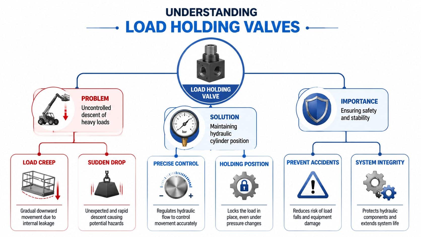
A load holding valve does one job very well, it stops a load moving when the hydraulic system loses pressure or when the actuator is being overrun by gravity or inertia. In practice, that means a telehandler boom stays put, a scissor lift doesn't settle overnight, and a cylinder on a press or clamp doesn't drift back under load. The valve sits in the circuit between the actuator and the directional control valve, so it can block or meter flow at the point where movement would otherwise start.
That matters because hydraulic lines alone don't guarantee safety. Hose elasticity, internal leakage, valve wear, and a loss of pump pressure can all let a load creep or drop if nothing is actively holding it. On lifting equipment, that becomes a compliance issue as well as a maintenance issue, because the system has to stay stable enough for the work it's doing.
What the valve is really promising
The promise is simple. When the machine is at rest, the valve locks the load side of the circuit. When the operator asks for movement, pilot pressure opens the valve so the load can lower in a controlled way rather than falling free.
That's why these valves turn up on excavators, loaders, access platforms, presses, and any hydraulic system that must hold position under a suspended or overrunning load. The valve is not there to make the machine clever. It's there to make the machine predictable.
A well-chosen valve also prevents the false confidence that comes from a circuit that “seems fine” in the workshop but settles in service. The difference shows up under heat, contamination, worn seals, or a line failure, which is exactly when the machine needs the holding device most.
How a Load Holding Valve Actually Works
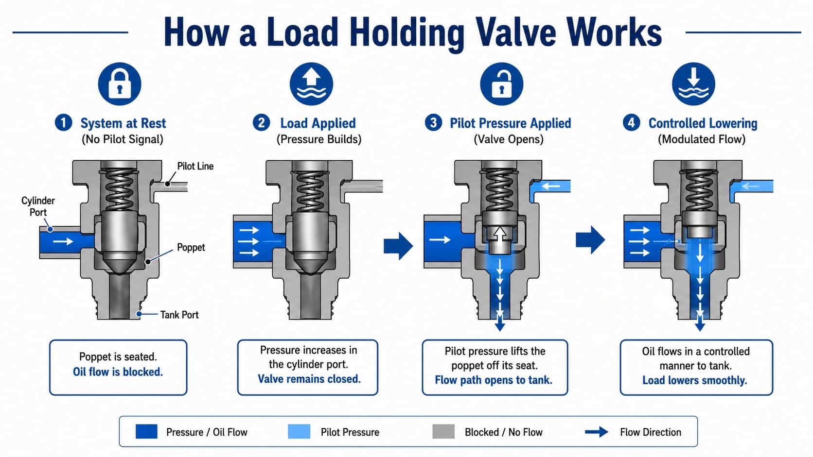
The valve uses a seated element, often a poppet, to block flow until a pilot signal tells it to open. With no pilot pressure, the load side stays isolated. That's why a cylinder can stay at the top of stroke without the pump doing any work, provided the circuit is sound and the valve is correctly set.
When the operator commands lowering, the pilot line feeds pressure to the valve and lifts the poppet off its seat. Oil then leaves the actuator in a controlled way, which is the whole point of the device. Wessel's VAL literature describes this as the load side being blocked without leakage until inlet pressure acts as a pilot control signal, after which the opening pressure can be adjusted so lowering stays precise and independent of the load (Wessel VAL technical literature).
Pilot ratio and setting margin
The opening effort depends on the pilot ratio. Manufacturer data show common ratios of 3:1, 4:1, 4.5:1, and 10:1, which means the pilot pressure needed to open the valve changes depending on the internal geometry (Yuken load-holding cartridge valve data). A higher ratio reduces the pilot pressure needed, so the valve opens more easily and lowering can feel smoother.
The set pressure matters just as much. A commonly specified rule is to set the valve about 15% above the maximum load pressure, and that same guidance is also stated as at least 1.3 times the load-induced pressure in technical training material (HAWE setting guidance, Sun Hydraulics training material). That margin keeps the valve shut under static load, but lets it open cleanly when the pilot signal arrives.
The mistake I see most often is fitting a valve that's too easy to open, then wondering why the load feels soft or drifts under dirty conditions.
The opening sequence is what you'd sketch on a whiteboard, no mystery required. Rest, load, pilot signal, controlled lowering. If the valve is installed and tuned properly, the lowering speed comes from the circuit design, not from the load deciding how fast it wants to move.
The Main Types and Where Each One Fits
A UK buyer usually ends up choosing between four practical valve families. They are not interchangeable, because each one answers a different circuit problem. The right choice depends on whether the machine only needs to hold position, or whether it also has to lower or arrest an overrunning load in a controlled way.
| Type | Typical Pressure Range | Best For | Leakage Behaviour |
|---|---|---|---|
| Direct-acting load holding valve | Modest pressure duties | Simple, low-flow circuits | Low, but not the main strength |
| Pilot-operated check valve | Application dependent | Static holding only | Near-zero leakage |
| Counterbalance valve | Commonly up to 350 bar, some families to 420 bar | Overrunning loads and controlled lowering | Tight, but designed to modulate |
| Integrated cartridge or dual valve | Commonly up to 350 bar, some selected sizes to 420 bar | Compact modern manifolds and OEM circuits | Depends on configuration |
The cheapest mistake is choosing for the wrong duty cycle. A pilot-operated check valve works well when the machine only needs to stay put. It is simple, non-modulating, and gives near-zero leakage, so it suits straightforward static retention. For a clear overview of how these families sit alongside other circuit components, the guide to types of hydraulic valves is a useful starting point.
A counterbalance valve earns its place when the load is trying to drive the actuator, or when controlled lowering is part of the job. That is the pattern you see on booms, lifts, and overrunning cylinders where gravity is part of the duty. It adds control, but it also adds tuning work. Get the setting wrong and the circuit can feel slow, harsh, or unstable.
Direct-acting and integrated cartridge designs are often used where packaging, response, and manifold integration matter more than broad catalogue simplicity. Modern families show how specific these devices have become. HAWE's LHDV technical datasheet lists defined setting ranges such as 50 to 250 bar, 251 to 350 bar, and 351 to 420 bar, plus associated pilot and shock-valve settings (HAWE LHDV technical datasheet). That is not a generic shutoff part. It is a precision component matched to a particular circuit duty.
The practical split is straightforward. If the load must only be held and there is no real overrunning tendency, a pilot-operated check is often enough. If the actuator can run away under gravity or stored energy, or if descent needs to be metered rather than blocked, a counterbalance valve is the safer choice. That trade-off matters under UK LOLER expectations, because the valve choice has to match the actual load case, not just the easiest schematic to draw.
Sizing and Selection That Holds
Start with the load, not the valve. Work out the maximum load-induced pressure, the expected flow in l/min, the likely tank-line pressure, and whether the load is static or overrunning. If those figures are wrong, the catalogue page will not rescue the circuit.
A sound sizing check compares the circuit demand with the valve's pressure and flow envelope. Mainstream cartridge and counterbalance designs are commonly rated to 350 bar maximum operating pressure with flow capacities from 30 to 350 l/min, while some load-holding families extend to 420 bar at selected sizes (Hydreco cartridge data). Under-sizing raises pressure drop and heat. Over-sizing can make lowering unstable and can make tuning awkward on descent.
A common mistake is treating the valve as a generic pressure device. The circuit has to be checked against the actuator, the load path, and the way the machine behaves in motion. If the cylinder must move smoothly under load, a valve that is fine on paper can still feel wrong in the hand.
What to lock down before you place an order
- Calculate the load pressure: use cylinder force and area, then add any overrunning effect.
- Check the flow demand: the valve has to pass the required l/min without creating excess restriction. If you are cross-checking from a data plate or test sheet, use thecalcs psi to gpm to keep the figures straight.
- Choose the pilot ratio: common options such as 3:1, 4:1, 4.5:1, and 10:1 change how hard the valve is to open (Yuken data).
- Set the margin correctly: a practical starting point is about 15% above maximum load pressure, or at least 1.3 times load-induced pressure (HAWE setting guidance, Sun Hydraulics training material).
- Confirm leakage acceptance: some valves quote 5 drops/min at reseat, others 15 drops/min, so you need to know what creep is acceptable in service (Yuken data).
That last point matters on site. A machine that creeps a little on the bench can become a problem once hoses heat up, seals bed in, and a suspended load sits for hours. UK LOLER expectations push you toward a selection that suits the actual duty, not just the neat schematic.
For UK kit, I would always check the lowering behaviour under a loaded test before signing it off. A simple pilot-operated check is enough when the cylinder only needs to be locked and there is no meaningful overrunning tendency. A counterbalance valve earns its keep when gravity, stored energy, or a driving load can run the actuator away, or when descent must be metered rather than just blocked. The pilot ratio decides how much pilot pressure is needed to open the valve, so a high ratio can make a circuit easier to release, while a lower ratio can improve stability when the load wants to overrun.
A valve that is too small buys heat. A valve that is too large for the duty can buy instability.
Keep the selection tied to the machine behaviour, then choose the family and pilot ratio that match the motion you need.
Installation and Piping Best Practice
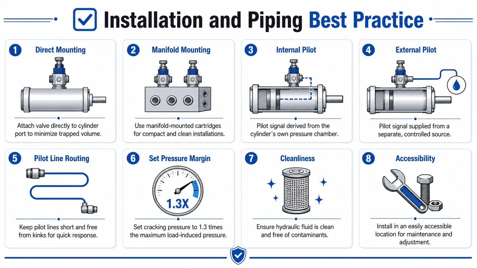
A load holding valve can be specified correctly and still give trouble if the piping is lazy or the mounting is awkward. On mobile plant, I want the valve as close to the actuator as the design allows, often straight on the cylinder port or built into a tidy manifold block. That keeps the trapped volume down and gives the valve the shortest practical path to the load.
Pilot routing is where a lot of installations fall apart. An internal pilot takes the signal from the cylinder's own pressure chamber, while an external pilot brings it from a separate controlled source. Long pilot lines, sharp bends, restrictive fittings, and shared pilot circuits all slow the opening response and can set up chatter.
What good install practice looks like
- Direct mounting: place the valve on the cylinder port where possible, so there is less trapped oil.
- Manifold mounting: use cartridge or block-mounted arrangements when space is tight and service access still matters.
- Short pilot lines: keep them short, straight, and protected from damage.
- Clean fluid: contamination shows up quickly as seat leakage or sticking in the pilot stage.
- Accessible adjustment: the fitter should reach the setting without stripping half the machine.
Cleanliness matters more than many teams admit. Independent datasheets point to contamination control around ISO 4406 19/17/14 or NAS 8, which is a practical benchmark for maintenance teams because dirt on seat faces changes how the valve opens and reseats. On a retrofit, I would rather spend time flushing pipework and checking pilot routing than chasing an intermittent creep fault later.
A well-laid-out circuit also makes later adjustment safer. For a practical reference on fitting valves neatly into existing pipework, use inline valve installation when a retrofit has to fit an older manifold or when space is tight and the installer needs a clear pattern to follow.
Real UK Applications and Application Examples
An excavator boom is the classic overrunning-load case. Gravity wants to pull the boom down faster than the pump wants to feed it, so a counterbalance valve is usually the right choice when controlled lowering is part of the duty. The setting normally lands in the lower-to-mid end of the valve family's working range, with the exact figure driven by the cylinder geometry and the load pressure margin already discussed.
A telehandler is trickier because lifting and slewing can both influence how the load behaves. That's where dual-valve logic or a compact integrated arrangement can make sense, especially when the boom has to stay stable while the machine moves. The valve choice needs to support both holding and smooth control, not just one of them.
A scissor lift or access platform is where I become conservative very quickly. The safety case sits close to LOLER expectations, so the circuit needs reliable holding, predictable opening, and proper examination intervals. If the duty is mostly holding with limited dynamic motion, a pilot-operated check valve or a carefully tuned counterbalance arrangement may both be candidates, but the final choice should follow the motion profile, not habit.
For a press or clamp tool, the priorities change again. Static hold and low leakage usually matter more than controlled descent, so the circuit can often stay simpler. If the machine only needs to park a load, the simpler holding option is often enough.
Fleet teams who run mixed equipment can use payload management for fleet operators as a reminder that load control starts before the machine is even on site. If the application is mis-specified, the valve ends up being asked to cover a design problem.
Maintenance and Troubleshooting in the Field
Creep after setting is usually the first complaint from the shop floor. When a load starts to move slowly after the valve has been adjusted, I look first for worn seats, contamination, or leakage past the reseat point. Some valves are specified at 5 drops/min and others at 15 drops/min at reseat, so the fitter needs the right acceptance figure before calling the valve healthy.
Chatter or oscillation usually points to the pilot side. A poor pilot ratio, air in the pilot line, or a pilot orifice that is too small can make the valve unstable during lowering. If opening pressure sits too close to the load pressure, the valve can hunt instead of opening cleanly.
Symptom to cause mapping
- Load creeps down slowly: likely seat wear, dirt, or incorrect setting.
- Valve chatters during lowering: pilot ratio mismatch, air in the line, or poor pilot routing.
- Load drops when pressure is lost: failed pilot stage or the wrong valve variant for the duty.
- System runs hot: valve is too large or the circuit is wasting pressure across an oversized restriction.
Overheating is often misunderstood. If the valve is oversized for the actual flow path, the machine can spend its life making heat instead of doing work. That is why sizing from the duty case matters before you even think about brand or body style.
Cleanliness is not optional. Independent datasheets point to ISO 4406 19/17/14 or NAS 8 as a useful cleanliness benchmark, which gives maintenance teams a practical target for flushing, filtration checks, and oil sampling. In service, I treat a six-monthly valve check as a sensible floor, because it sits comfortably with the UK examination rhythm already used for lifting equipment.
For a fault-finding checklist, the guide on common hydraulic valve problems and fixes is a sensible companion when the symptom is obvious but the cause is not.
Putting It Together Next Steps
A proper selection process is straightforward. Define whether the machine needs static holding or controlled motion, calculate the load-induced pressure, choose the valve family, then lock in the pilot ratio and the setting margin. After that, confirm cleanliness, pilot line layout, and how the inspection schedule sits alongside the relevant LOLER examination interval.
If the circuit only needs parking, don't overbuy control you won't use. If the load can run away under gravity or inertia, don't try to save money with a valve that can only hold statically. That decision is usually where good installs are won or lost.
MA Hydraulics Ltd can help with valve cross-referencing, sizing support, and matching the holding circuit to the machine duty, whether it's a retrofit or a new build. The key is to get the valve, the pipework, and the service interval aligned before the machine goes back to work.
If you need help selecting or cross-referencing load holding valves for a UK machine, speak to MA Hydraulics Ltd for practical sizing support and valve supply across mobile and industrial circuits. Visit MA Hydraulics Ltd or phone 01724 279508 today, and get the holding circuit checked before the next lift, lower, or retrofit goes live.
