
A machine is down, the operator is waiting, and someone has already asked how long the repair will take. That's usually when inline valve installation stops being a tidy workshop exercise and becomes a real test of judgement. The valve itself might be small, but if you fit it badly, the fault won't stay small for long. You'll see leaks, heat build-up, chatter, damaged seals, and a second shutdown that was entirely avoidable.
In hydraulics, the job is rarely just “swap the valve”. You're dealing with pipework that has moved over time, fittings that have been overtightened before, contamination that nobody admitted was in the line, and assemblies that only look straight until you put a straightedge on them. Manuals give you the sequence. They often don't tell you what to watch for when the pipe run is under strain, the access is poor, and production wants the plant back now.
Your Guide to Flawless Inline Valve Installation
A proper installation protects more than the valve. It protects the pump upstream, the actuator downstream, the seals throughout the circuit, and the people working around the machine. If you rush alignment or ignore mounting stress, the system will tell you. Usually through vibration first, then through leakage, then through a call-out that should never have happened.
That matters because inline valves sit in a market that remains central to UK industry. The UK Industrial & Fluid Power Valve Manufacturing industry generated a market size of approximately £142 million in 2023, reflecting demand across manufacturing, waterworks, and energy sectors that depend on precise flow control for system integrity and operational safety, according to IBISWorld's UK industry overview.
What good installers do differently
The technicians who get these jobs right don't rely on luck. They do a few basic things every time:
- They verify the duty, not just the thread or flange size.
- They read the valve body, especially flow direction and mounting limitations.
- They correct the pipe run first, rather than forcing the valve to make up the gap.
- They test methodically, instead of pressurising hard and hoping for the best.
Practical rule: If the valve only fits when you pull the line into place with the bolts, the line is wrong. Fix the line, not the symptom.
There's also value in looking outside pure industrial hydraulics now and then. Domestic guidance can sharpen your eye for isolation, flow direction and neat installation habits, particularly for junior fitters. A concise example is this home heating control guide, which shows how the same fundamentals apply even when the application is much simpler.
The commercial reality of getting it wrong
A bad installation costs more than the price of a replacement valve. It adds labour, fluid loss, cleanup, retesting, machine downtime, and wasted fault-finding hours when people start blaming pumps, cylinders or control blocks. On mobile plant, it can also leave a machine unreliable in the field, which is far more expensive than catching the issue on the bench.
The aim is simple. Fit the valve so it sits naturally, seals properly, and behaves predictably under load. That's the standard worth holding.
Planning and Selecting the Right Inline Valve
Most failures start before a spanner touches the machine. They start with the wrong valve, the wrong seal material, or a rushed assumption that “it looks about right”. Planning is where you prevent almost all of that.

Match the valve to the duty
Start with the system data, not the old part number. Check maximum operating pressure, expected flow, temperature range, fluid type, port specification and the valve function required in that position. A non-return valve, relief valve, flow control valve and sequence valve may all look similar on a shelf. In service, they're doing very different jobs.
If you need a refresher on circuit functions before choosing the replacement, MA Hydraulics has a useful overview of types of hydraulic valves. That's often enough to stop a junior technician fitting a valve that physically screws in but is wrong for the circuit.
Inspect the new valve before installation
Don't open the box and assume the component is ready. Check it.
Use this quick bench check:
- Body condition: Look for cracked castings, damaged threads, distorted flanges, and impact marks from transit.
- Ports and plugs: Make sure protective caps were fitted and that no debris has entered the ports.
- Markings: Confirm the pressure rating, part number, flow arrow, and any mounting orientation marks.
- Actuation and movement: If the design allows manual checking, make sure nothing feels stiff, gritty or obviously incorrect.
A valve with a damaged port face or bruised thread can waste hours. The leak won't always show up until pressure is back in the line.
Prepare the work area properly
A neat installation starts with a controlled work area. That means full isolation, lockout, depressurisation, fluid containment and enough room to support the line while you work. If you can't support the pipework, you'll fight alignment the entire time.
Don't trust a gauge alone to prove a line is safe. Crack the system down in a controlled manner and confirm there's no trapped pressure before separating any connection.
Have absorbent pads, drain trays, clean caps and plugs, the correct seals, a calibrated torque wrench, and cleaning materials ready before you begin. If you have to stop mid-job to hunt for the right adaptor or thread sealant, the chances of dirt ingress and rushed reassembly go up sharply.
Think about what the old valve is telling you
The removed valve is evidence. Read it before you bin it.
A quick comparison helps:
| What you find on the old valve | What it often means |
|---|---|
| Localised wear on one side | Pipe misalignment or side load |
| Debris in the internals | Poor cleanliness or no effective upstream protection |
| Burnt or hardened seals | Heat, wrong fluid, or sustained pressure stress |
| Damaged threads or flange faces | Previous overtightening or poor assembly practice |
That small inspection often tells you whether the replacement will live a long life or fail in the same way.
Correct Mounting and Piping for Inline Valves
Good intentions usually meet awkward reality. The line is never quite where the drawing says it should be. One clamp is missing, one support is loose, and the old valve has been masking poor pipework for years. Your job is to install the new valve without building that stress back into the system.
The installation flow below is a sensible working sequence.
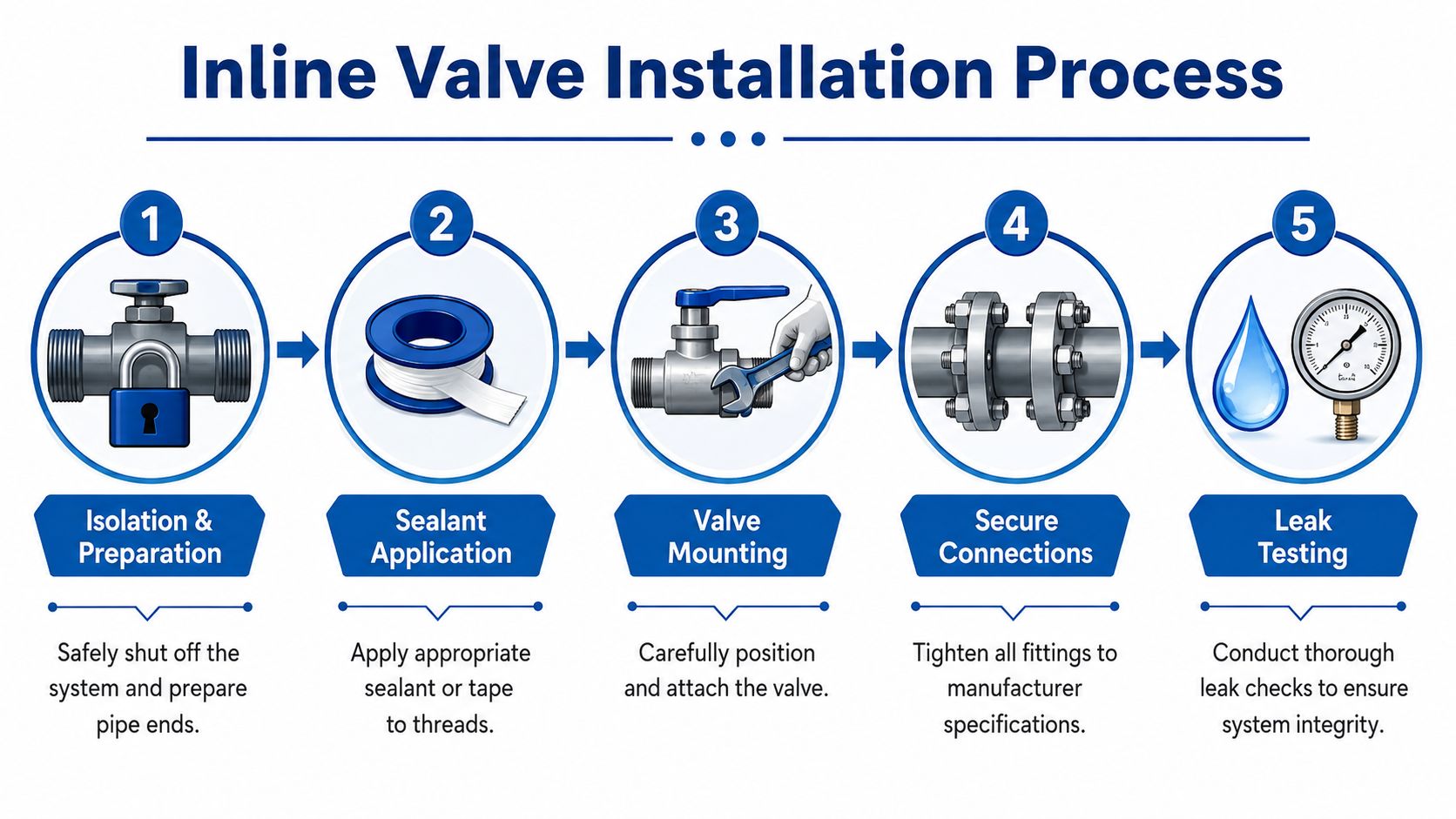
Isolate, support, then offer up the valve
Depressurise the circuit fully and make sure any suspended load is mechanically supported. On mobile equipment, that can mean more than one support point. Never assume hydraulic holding alone is enough once you start opening the line.
Before the valve goes anywhere near the pipework, clean the mating connections and check the line can sit naturally in position. If the pipe springs away when disconnected, note that immediately. It means stored stress is already in the run.
Respect the flow path and straight runs
An inline valve only works properly if the fluid reaches it cleanly and leaves it cleanly. Best practice is at least 5 pipe diameters of straight pipe upstream and at least 5 pipe diameters downstream to reduce turbulence and maintain stable flow, as set out in Tameson’s check valve installation guidance. That’s one of those details fitters skip when space is tight, then wonder why the valve chatters or behaves inconsistently.
Check the flow arrow on the body and align it with the actual circuit direction. Not the assumed direction. Not the old fitter’s paint mark. The actual direction of flow in service.
A few common mounting mistakes cause repeated trouble:
- Forcing offset pipework into line: The valve becomes a structural member instead of a flow control component.
- Ignoring nearby elbows or tees: Disturbed flow enters the valve and affects operation.
- Mounting without support: Vibration and pipe weight get transferred straight into the body.
- Reusing suspect fittings: A tired adaptor can turn a sound valve installation into a leak path.
If the valve body is carrying pipe strain, the seals are already working against a problem they were never meant to solve.
Get the alignment right in the real world
This is the bit manuals usually underplay. “Align the valve” sounds simple until you’re kneeling beside a machine with uneven brackets, repaired pipework and limited movement in the hose or tube assembly.
Field data from UK hydraulic repair teams shows that angular deviations beyond 3.175 mm cause flow restriction, vibration, and premature seal failure, and that same field guidance reinforces the need for straight pipe runs to avoid turbulence, as shown in this UK hydraulic repair demonstration.
The fix is rarely brute force. It’s usually one or more of these:
- Loosen adjacent supports so the line can relax before final positioning.
- Rework the pipe run if the valve gap is visibly out.
- Add or correct clamps so the line stays where you set it.
- Use the correct fitting stack, rather than creating a crooked assembly with adaptors.
Choose the best mounting orientation
Wherever possible, install inline valves in horizontal pipelines with the spindle positioned vertically. That arrangement is widely treated as best practice because it reduces stress effects from line distortion and helps the valve operate as intended. In awkward plant layouts, you won’t always get the ideal orientation, but you should understand what compromise you’re making before you accept it.
There’s another practical point here. If the line needs regular service access, think about tool clearance before final tightening. A valve that’s impossible to reach cleanly won’t be maintained properly later.
What works and what doesn’t
A quick comparison helps on site:
| Works | Doesn’t work |
|---|---|
| Supporting the pipe before disconnecting the old valve | Letting the line sag and then trying to “pull it back” |
| Dry fitting to check natural alignment | Applying sealant first and hoping the assembly lands correctly |
| Checking flow arrow against the circuit | Assuming the old installation was correct |
| Leaving proper straight runs where possible | Mounting hard against a bend or fitting because it’s convenient |
| Correcting the run with clamps and supports | Using the valve body to bridge poor geometry |
If a junior technician remembers one thing from this stage, it should be this. A valve should sit into the system. It should never be dragged into it.
Ensuring a Leak-Free and Secure Connection
A clean mount still fails if the jointing work is careless. Most leaks aren't mysterious. They come from damaged threads, poor surface prep, wrong sealant choice, uneven flange loading, or torque applied by feel instead of measurement.
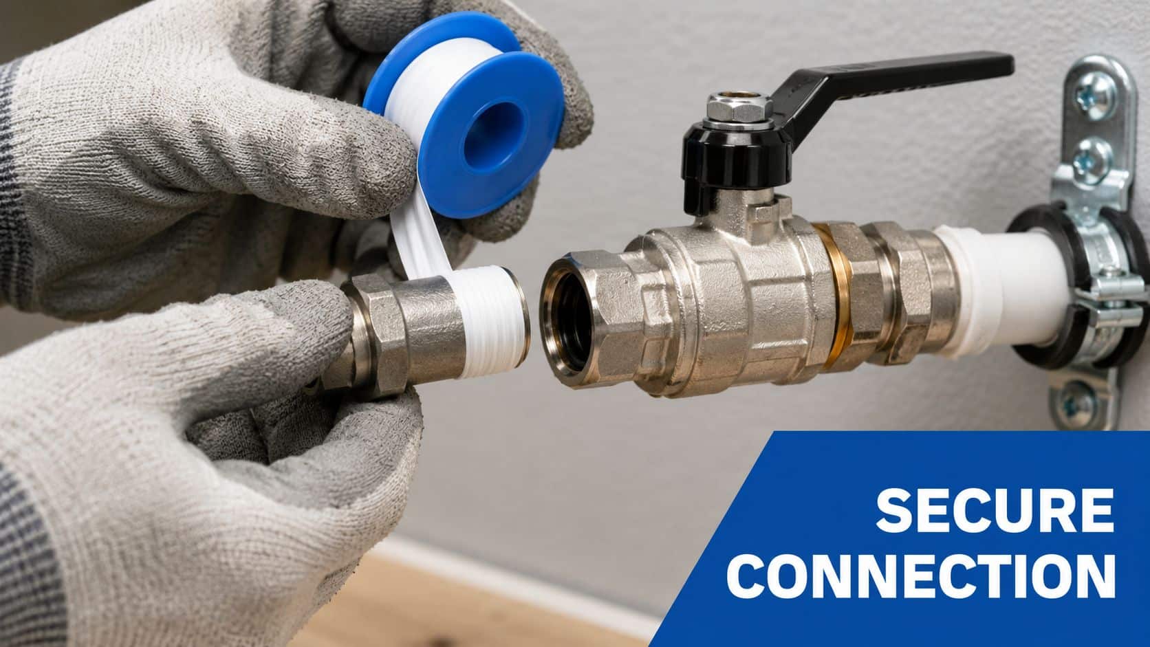
Seal threaded joints properly
Clean the male and female threads first. Old sealant, swarf and embedded dirt will stop the joint from seating correctly. Once the threads are clean and undamaged, apply PTFE tape or the specified liquid sealant in a controlled way. The tape needs to follow the direction of the thread so it doesn't bunch or unwind during assembly.
Use restraint here. Too little sealant can leak. Too much can shed into the system and create contamination problems downstream. If you're working across mixed connection types, it's worth reviewing the differences between ports and sealing methods in this guide to hydraulic fittings types.
Tighten flanges evenly
Flanged connections need even loading across the gasket face. Bring the bolts up gradually in a star or criss-cross pattern. Don't wind one side fully down and then chase the rest. That distorts the joint face and can pinch the seal.
A calibrated torque wrench matters here. “Nipped up” isn't a measurement. Overtightening can warp a flange or crush a seal, while undertightening leaves a leak path that may only show itself when the system gets warm or sees peak load.
Workshop habit: Mark each bolt head after final torque. It gives you a quick visual confirmation that nothing was missed.
Pressure test before service
Before commissioning, pressure testing needs to be treated as a formal step, not an optional extra. The recognised UK installation method requires adherence to BS EN 12266, including a hydrostatic test at 1.5 times operating pressure to confirm leak-free integrity before the valve goes into service, as outlined in Blackhall's valve installation guide.
Bring the test pressure up in a controlled manner. Watch the joint, the valve body, and any nearby adaptors or flanges. If a connection starts to weep, stop and rectify it properly. Don't keep pushing pressure into a suspect joint to see if it “beds in”.
For pressure relief and discharge arrangements, installation standards also require pressure drop during discharge to remain controlled. EN ISO 4126 recommends keeping pressure drop below 3% of the set pressure, as explained in Spirax Sarco's safety valve installation guidance.
Record what you've done
Good installers leave a traceable record. Log the valve type, location, sealing method, test completion, and any observations about pipe condition or alignment correction. That note can save a future engineer from stripping a perfectly sound assembly because the issue lies elsewhere in the circuit.
Commissioning Your Valve and Solving Common Issues
Commissioning is where the installation either proves itself or starts showing the shortcuts. Bring the system back gently. Don't slam full pressure into a new assembly and call it tested.
Start by reintroducing pressure slowly while watching every connection point. Check for weeping, not just obvious drips. Then cycle the valve through its operating range and confirm the circuit responds cleanly. If the machine has been opened for some time, allow for air purge and a short settling period before you judge the final result.
A sensible commissioning routine
Keep it orderly:
- Pressurise gradually: Let the seals and joints settle under controlled load.
- Inspect closely: Use clean tissue or card where appropriate to detect light weeping safely.
- Cycle the function: Make sure the valve shifts or regulates as intended.
- Listen to the system: Chatter, hiss, or sharp vibration usually points to an installation issue rather than bad luck.
- Update the paperwork: The final state should match your service record and test notes.
If you're working under a formal site regime, your broader commissioning procedures should sit alongside the valve-specific checks.
Inline Valve Installation Troubleshooting Guide
| Symptom | Likely Cause | Solution |
|---|---|---|
| Slow weep at threaded joint | Poor thread prep, wrong sealant, damaged thread | Depressurise, strip, inspect threads, reseal correctly, refit |
| Leak at flange after pressure rise | Uneven bolt loading or damaged gasket face | Replace seal if required, reassemble, torque in star pattern |
| Valve chatters in service | Disturbed flow, poor mounting position, line stress | Check nearby fittings, support the run properly, reassess orientation |
| Excessive vibration in pipework | Misalignment, unsupported line, stored pipe strain | Realign the assembly, adjust supports, remove side load |
| Valve sticks or responds poorly | Debris in line or wrong valve selection | Inspect cleanliness, verify duty and valve function |
| Noise under flow | Turbulence, trapped air, or restriction | Purge the system, inspect flow path, check the surrounding pipe layout |
A valve that works on the bench but misbehaves under load is often telling you about the pipework around it, not about the valve itself.
Read the symptoms in order
Start with what changed. If the issue appeared immediately after the inline valve installation, focus first on alignment, sealing, cleanliness and mounting stress. Don't jump straight to replacing the new component. Most post-installation faults are assembly related.
If the system operates smoothly at low demand and then becomes unstable under load, that usually points to flow conditions or mechanical stress showing themselves only when pressure and movement increase. That's why a proper commissioning check has to include the machine's real operating state, not just a static pressure hold.
Long-Term Safety, Maintenance, and Support
A sound installation is only the start of the valve's working life. If nobody inspects it again until the next failure, even a well-fitted component can end up blamed for problems caused by contamination, vibration, corrosion or poor support elsewhere in the circuit.
Keep the checks simple and repeatable
Use lockout and depressurisation every time you inspect or service the assembly. Then keep the routine practical:
- Look for early signs: Check for weeping, corrosion, paint disturbance around joints, and movement in supports.
- Confirm stability: If the valve is actuated, make sure the control side is behaving properly and consistently.
- Maintain records: Installation dates, seal changes, retorquing and fault notes build a useful service history.
For sites managing broader plant reliability programmes, these industrial maintenance support services show the kind of structured support model that helps keep critical assets under control.
Where application demands are unusual, component matching matters. MA Hydraulics Ltd stocks the OMT Group inline circuit valve range for mobile and industrial hydraulic applications, alongside related fittings and hydraulic components, which can be relevant when a replacement needs to match an existing circuit layout rather than only fit the port.
Good support matters when the line is awkward, the part is obscure, or the failure pattern doesn't make sense at first glance. That's when experienced technical advice saves time.
If you need help with MA Hydraulics Ltd component selection, replacement inline valves, or practical advice on a hydraulic system issue, phone 01724 279508 today or send us a message.
