The most common hydraulic hose failures are not random material defects. A reliability handbook citing fluid-power manufacturers says the big causes are abuse, misapplication, and improper assembly, and that 80% of hose failures come from external physical damage such as pulling, kinking, crushing, or abrasion (reliability handbook PDF). For a UK MRO team, that changes the first question after a burst or leak. The issue usually isn't solely how long the hose has been on the machine, it's what in the installation, routing, or handling set it up to fail.
That mindset matters because hose failures behave like a systems fault, not a calendar fault. If the route is tight, the fittings are mismatched, the hose is twisted, or the assembly was forced into place, the hose becomes the weak link long before its material life is used up. The practical payoff is straightforward, less repeat downtime, fewer emergency callouts, and better control of maintenance spend.
Why Most Hydraulic Hose Failures Are Preventable
A hose failure in the yard or on site usually starts with a choice, not a defect. In the workshop I see the same pattern again and again, a hose that was routed too tightly, fitted under strain, left to rub, or matched to the wrong assembly parts. That is why repeat failures are a systems and workmanship problem first, and a hose-life problem second.
Stop treating hoses like disposable consumables
A failed hose often points straight back to the machine around it. Tight routing, poor clamp placement, bent end fittings, or a hose left to move against a bracket all show a control failure in installation and maintenance. The practical point is simple, if the assembly is being forced to do work it was never meant to do, it will fail early, and it will usually fail in the same way next time.
A UK maintenance team can see the cost of that mistake very quickly. One repeat burst on a mobile machine often means a callout, lost production, fluid clean-up, and a second repair that costs more than doing the root-cause check properly the first time. In real terms, the cheaper fix is the one that stops the next failure, not the one that gets the machine moving for the moment.
The reliability handbook points to bending below minimum bend radius, twisting, kinking, crushing, abrasion, temperature overload, pressure surges above the maximum operating pressure, and incompatible hose and fitting combinations as recurring failure mechanisms (reliability handbook PDF).
A failed hose should trigger a route and assembly review first, not a parts-only replacement.
That mindset matters on mobile plant, agricultural machinery, and industrial equipment in UK conditions. Cold mornings, vibration, tight service spaces, and hurried breakdown repairs all make bad routing and poor assembly show up faster. If the same fault keeps coming back, the hose is usually not the actual problem, the route, the clamp arrangement, the fitting selection, or the operating envelope still is.
What this means on the workshop floor
The response has to be disciplined, not improvised. Match the hose to the actual duty cycle, keep the installed shape within the hose's design limits, and assemble it the same way every time, with the right parts and the right orientation. That reduces repeat failures because it removes the predictable stress points that keep wearing out otherwise serviceable hose assemblies.
The Main Hydraulic Hose Failure Modes Explained
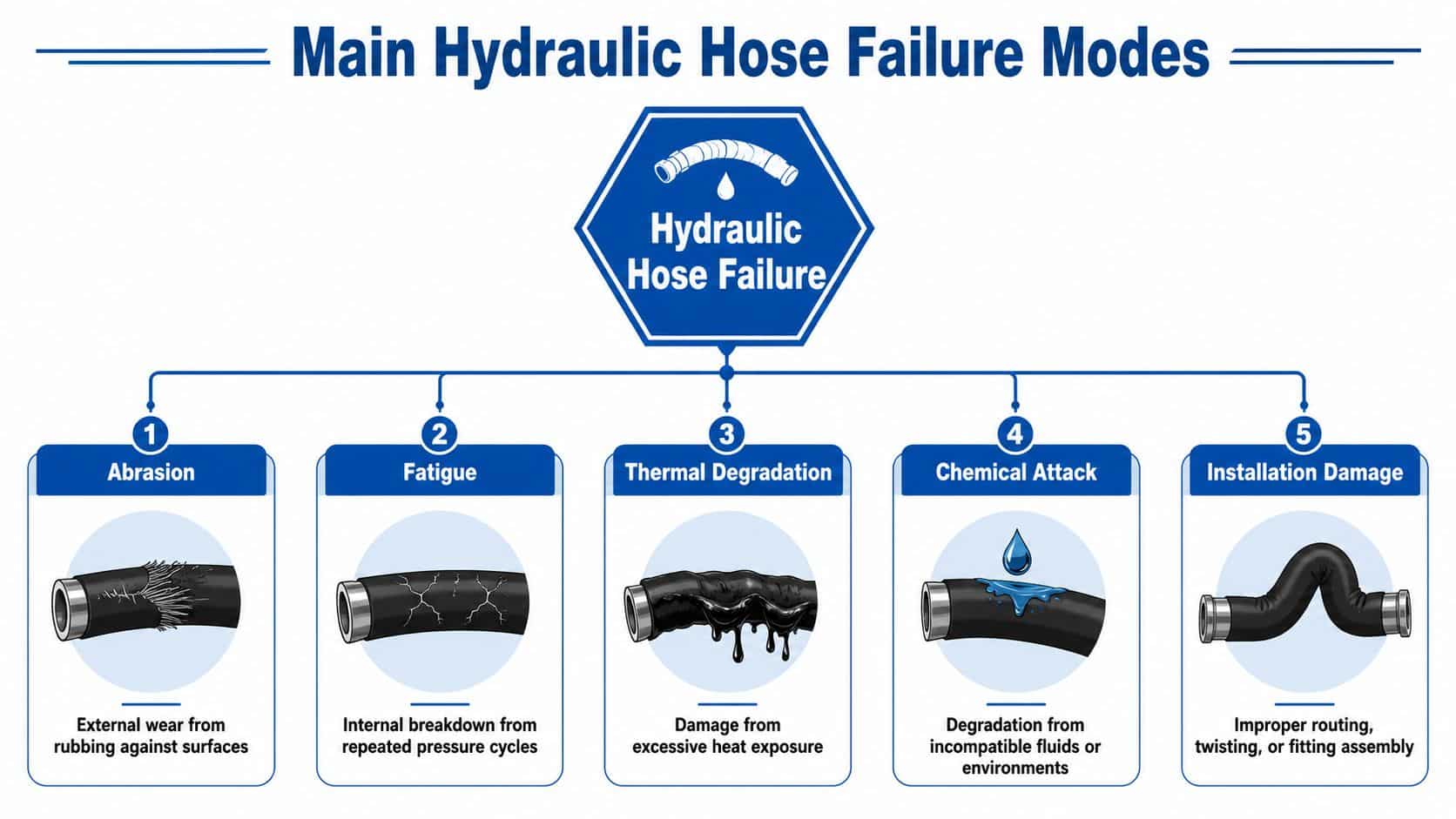
The fastest way to diagnose a failed hose is to inspect the outside first, then trace the symptom back to the cause. A hose rarely fails without leaving a pattern you can read. The cover, the fittings, and the way the assembly sits in the machine usually show what went wrong.
What the failure looks like on the hose
A rubbed or thinned outer cover points to abrasion, especially where the hose has been allowed to move against another hose, a bracket, or a machine edge. A cracked or stiffened outer layer usually points to thermal degradation, where the hose has lived too close to a heat source or outside its temperature envelope. A hose that looks blistered, swollen, or internally damaged may be reacting to chemical attack, while a hose with a kinked shape, flattened bend, or twist at the end usually points to installation damage.
A leaking fitting tells a different story. It usually points to poor assembly, the wrong component pairing, misalignment, or a connection that has been stressed by movement after installation. In the field, I treat seepage at the end of a hose as a sign that the assembly and routing need to be checked together, not as separate jobs.
The root cause is often mechanical stress
The damage often starts before the leak appears. Repeated pressure cycling can contribute to fatigue, but in day-to-day maintenance work the larger issue is usually installation-induced stress, forced bends, torsion, crimping defects, and poor restraint. The technical literature on hose malfunction links those conditions directly to failures after commissioning, because strain concentrates at the ends and through the reinforcement layers until the cover breaches or the fitting starts to leak (hose malfunction analysis).
If a hose shows twist, flattening, scuffing, or fitting-end seepage, treat it as a routing or assembly fault until proven otherwise.
Contaminated fluid can also drive internal abrasion, because dirt, metal particles, and debris wear the hose from the inside and weaken it until it becomes more vulnerable to bursting under pressure. That is why a failed hose should not be diagnosed in isolation. Look at the hose, the fittings, the route, and the fluid condition as one failure chain.
A useful field rule
When the outside of the hose tells a clear story, believe it. Abrasion means movement and contact. Twist means installation error. Leaks at the end mean stress, alignment, or assembly trouble. That simple classification saves time and pushes repairs toward the actual fault instead of the symptom alone.
A technician-led visual pass is often enough to separate the obvious failures from the ones that need deeper testing. Keep the route clear, keep the hose within its bend limits, and look for the places where the machine has been wearing the assembly down.
You can also compare the same hose route with proper support and restraint hardware, including the right clamp arrangement, on the machine's tubing and hose runs. If the route is changing shape or hanging unsupported, the assembly is already working harder than it should. See the practical layout approach used for clamp for tubing.
How Abrasion and Routing Drive Premature Failures
Abrasion deserves special attention because it's one of the most preventable causes of early hose loss. An industry analysis says more than 57% of premature hose failures result from abrasion caused by improper routing (Plant Engineering analysis). That's the number that should change the way a maintenance team walks around a machine. Before blaming the hose, check where it's touching, rubbing, or being forced to move.
Why compact layouts make hoses fail early
Compact UK equipment often leaves little space for clean hose routing. Hoses end up crossing each other, laying against steelwork, or bending tightly as the boom, arm, carriage, or implement moves. Once the cover starts rubbing, the damage progresses from cosmetic wear to reinforcement exposure, and then to leakage or rupture.
The trouble is that abrasion often looks minor early on. A polished patch, a shiny scuff, or a light flat spot can seem harmless, but those marks tell you the hose is moving against something under load. In a vibrating or articulated machine, that contact repeats every cycle until the cover gives way.
What holds up better in the field
Good routing is usually less about the hose itself and more about how the machine is managed. Clamp spacing, slack control, sleeve protection, and bend radius compliance all matter because they stop the hose from becoming a moving chafe point. The right support hardware keeps the hose in a controlled path, rather than letting it bounce, sag, or rub against hot or sharp surfaces.
A few checks give you most of the benefit:
- Look for contact points: Check where hoses touch other hoses, frame edges, guards, cylinders, or moving parts.
- Follow the movement path: Watch the machine through its full working stroke, because some rub points only appear under articulation.
- Keep bend radius sensible: A hose that looks fine at rest can become overstressed once the machine moves.
- Use protection where the route can't be perfect: Sleeves, guards, and restraints are often the difference between a tidy route and a recurring failure.
If a route depends on the hose “just not moving”, it's already the wrong route.
A lot of repeat failures get fixed the moment someone stops accepting contact as normal. In practice, that means rerouting hoses away from hard edges, using restraint properly, and replacing any assembly that already shows chafe damage before it turns into a pressure-side failure.
Inspection and Diagnostic Steps for MRO Teams
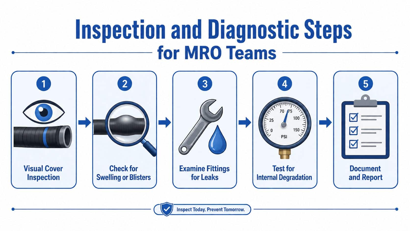
A repeat failure rarely starts with the hose alone. It usually starts with a missed detail in inspection, a weak handover note, or a machine that was put back into service without enough evidence to show why the first hose failed. A clean diagnostic process stops that cycle.
Start with the simplest evidence and work outwards. Look at the failed assembly, confirm where the damage began, check the fittings, then record the route, machine condition, and operating context before anyone orders a replacement.
Work through the hose in the right order
Begin with the outer cover and the area around the failure point. Look for scuffing, cuts, polished patches, blistering, flattening, hardening, or local discolouration, because those signs help separate wear, heat, impact, and pressure-related damage. Then inspect the fittings for seepage, rust staining, movement marks, or visible pull-out.
After that, check the assembly as it sat on the machine. Note the hose identification, age if it is known, the fitting type, the clamp arrangement, and the exact location of the failure. Photograph the assembly before it is disturbed, because once the hose is off the machine, the evidence often becomes harder to read.
Don't ignore fluid and operating conditions
Visible damage only tells part of the story. Cleanliness history, duty cycle, and temperature all shape how a hose behaves in service. Contaminated fluid can wear a hose from the inside, so a dirty oil sample, a poor filtration record, or recurring debris in the system should be logged alongside the failure report.
Pressure spikes matter as well, especially on machines that cycle hard or sit close to their working limit. That is the point where thermal stress often shows up too, and a thermal imaging inspection can help you spot heat sources around manifolds, exhausts, pumps, or electrical enclosures that shorten hose life. It will not replace a visual check, but it gives the MRO team another way to separate a local heat problem from a general hose defect.
Practical rule: if the failed hose came off a machine that has poor oil cleanliness, hot running conditions, or repeated rework, treat the assembly as part of a system fault, not a stand-alone spare issue.
The best teams document the job while they inspect it. Record the hose type, failure location, visible wear pattern, fitting condition, machine duty, and any recent maintenance work. That makes repeat failures easier to compare, especially when the same pattern starts showing up across more than one asset.
A short diagnosis note should also say what was checked and what was ruled out. That keeps later reviews focused on the actual fault chain, not on guesswork about the part that happened to burst first.
Choosing the Right Hose and Fitting Combination
Hose selection has to match the actual machine, not the catalogue picture of it. A hose can look correct on paper and still fail early if the working pressure, surge load, temperature, bend radius, or fluid compatibility doesn't match the actual duty cycle. Parker Hannifin's hose-failure guidance puts improper component selection, incorrect assembly procedure, and poor installation practice at the centre of the failure model, and that lines up with what turns up in the field (Parker Hannifin hose failure guide).
Selection checks that matter on the machine
| Selection Check | What to Verify on the Datasheet | What to Measure on the Machine |
|---|---|---|
| Pressure rating | Working pressure and surge tolerance | Actual system pressure during use |
| Temperature range | Hose and fitting temperature limits | Heat near manifolds, engines, ovens, or exhausts |
| Bend radius | Minimum bend radius for the assembly | Installed route at full articulation |
| Fluid compatibility | Hose tube and cover compatibility | Hydraulic fluid type and any contamination risk |
The aim is simple. Don’t choose on size alone. The hose has to survive the machine’s motion, heat, pressure spikes, and fluid chemistry at the same time.
Fittings and assembly quality are part of selection
A hose and fitting are one assembly, not two separate parts. If the fitting style is wrong, the crimp dimensions are off, or the hose and end are poorly aligned, the end of the assembly becomes the weak point. That’s why mixing parts without checking compatibility can create a good-looking assembly that fails in service.
Use hydraulic fittings types as a reference point when the existing connection is being replaced or cross-matched. The primary concern is not just whether the thread fits, but whether the combined hose, fitting, orientation, and installed shape will stay stable under load.
What good procurement looks like
Better selection saves work later because it reduces the chances of a hose being forced to operate outside its envelope. For MRO and design teams, that means checking the rating against the actual duty, verifying the end style, and making sure the installed geometry is achievable without twisting or crush loading the hose. When those checks are skipped, the repair may hold for a while, but the same assembly often comes back through the workshop with a fresh leak or a blown end.
Real-World Scenarios From UK Mobile and Industrial Use
A construction or agricultural machine often tells the same story. A hose is replaced after a leak, the new one is fitted to the same tight route, and the root problem is left untouched. The next failure appears a few weeks or months later at the same chafe point, because the hose is still rubbing the frame or the adjacent line during every cycle.
In a second common scenario, an industrial hydraulic power pack gets a replacement hose with an old fitting reused because it “looked fine”. The system runs for a while, then the connection starts to seep because the assembly was never properly matched or aligned. The repair looks cheaper on the day, but it creates another shutdown later.
The pattern is usually small decisions piling up
A hose routed too close to a hot manifold will harden and age faster than the identical hose routed cleanly across the same machine. A hose that’s left with twist in the line will fatigue sooner at the end connection. A line that’s not clamped properly will walk into contact with other parts, and the contact becomes the failure.
That’s why the same hose type can have a very different life in two machines doing similar work. One operator gets a stable route, proper restraint, and clean assembly practice. The other gets a quick swap, a reused end, and no check for movement at full stroke.
The machine rarely hides the cause. It usually shows it at the exact point where the hose was forced to live with bad geometry.
For UK fleets, the lesson is consistent. The most reliable assemblies aren’t necessarily the most expensive parts, they’re the ones installed with enough room, restraint, and compatibility to survive real movement. When a machine keeps losing the same hose, the pattern usually sits in the routing, the fittings, or the service habits, not in the brand name on the cover.
A Practical Troubleshooting and Prevention Checklist
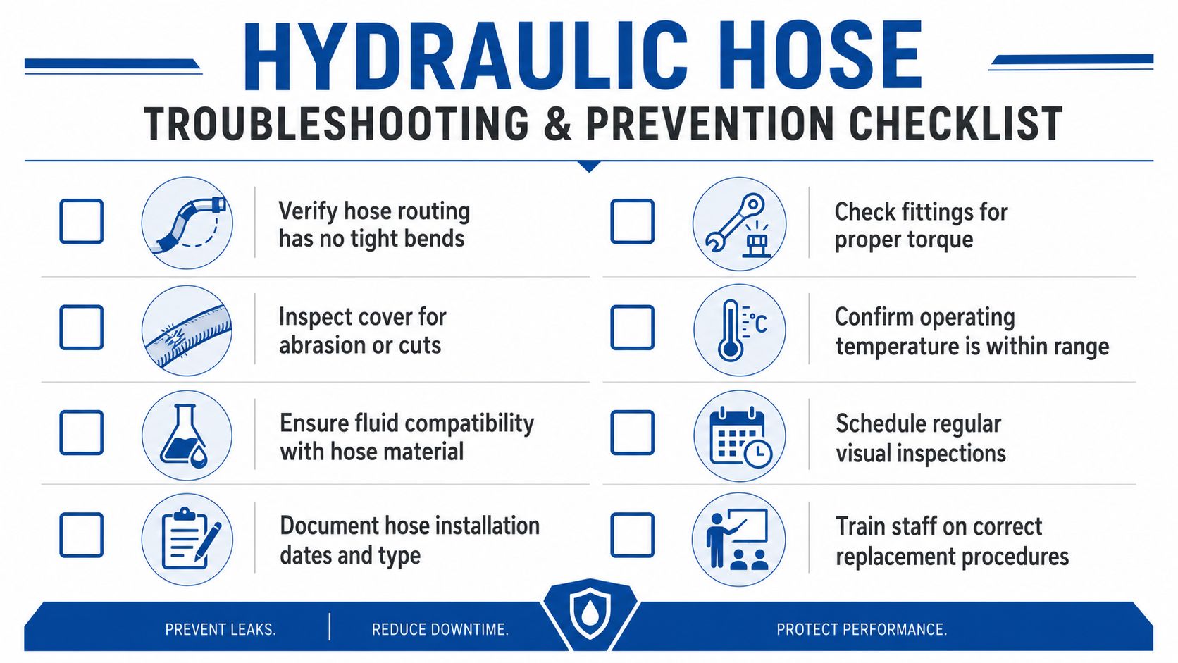
Use this as a shop-floor reset when a hose fails, or as a pre-service check before the next machine goes back out.
- Verify hose routing has no tight bends. Check the full machine movement, not just the parked position.
- Check fittings for proper torque and alignment. A good seal still fails if the assembly is stressed.
- Inspect the cover for abrasion or cuts. Any chafe mark needs a route review.
- Confirm operating temperature stays within range. Look for nearby heat sources, not just system readings.
- Make sure the fluid matches the hose material. Contamination and incompatibility shorten service life.
- Schedule regular visual inspections. Early scuffing is cheaper to fix than a rupture.
- Record installation dates and hose type. That makes repeat failures easier to trace.
- Train staff on correct replacement procedures. A fast repair that ignores twist or bend radius just creates the next breakdown.
The practical rule is simple. If a hose failed, don’t just replace the hose, correct the reason it failed. That means looking at routing, restraint, assembly, fluid cleanliness, heat exposure, and component compatibility as one maintenance problem.
Visit MA Hydraulics Ltd for technical support, or phone 01724 279508 today, or send a message through the contact page to discuss the right components for your job.