A clamp usually gets attention only after something else has gone wrong. The hose starts chafing. A fitting works loose. The power pack develops an irritating vibration that becomes a leak on a cold Monday morning. Then everyone traces the fault back to a part that looked minor during build.
That’s why clamp selection deserves more thought than “match the diameter and move on”. The right clamp for tubing protects hoses, tube runs, valves, manifolds and pump connections from movement they were never meant to absorb. The wrong one stores up maintenance work, unplanned stoppages and avoidable replacement costs.
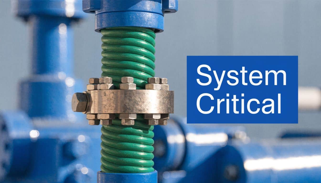
Why the Humble Clamp is Critical for Hydraulic System Health
A hydraulic system rarely fails because of one dramatic mistake. More often, it fails because several small compromises stack up. A poor clamp choice is one of those compromises. It lets a tube run vibrate slightly, that vibration reaches the fitting, the fitting starts fretting, and the leak appears months after commissioning when the original decision has been forgotten.
The practical issue isn’t only fluid loss. Once tubing is free to move, it starts loading other components. Gear pumps don’t like inlet or return lines pulling on connections. Directional valves don’t benefit from repeated stress at ports. Even a tidy-looking assembly can become noisy, difficult to service and unreliable if the line support strategy is poor.
What a clamp is actually doing
A good clamp for tubing does several jobs at once:
- Supports line routing: It keeps tube and hose runs where the design intended them to be.
- Controls vibration: It limits movement before that movement becomes fatigue.
- Reduces noise: Proper isolation stops pipework from turning frames and panels into sounding boards.
- Protects expensive components: It prevents loads from being transferred into pump bodies, valve blocks and fittings.
Practical rule: If a line can move by hand more than you’d accept while the machine is running, the clamp arrangement probably needs work.
The wider market points in the same direction. The global pipe clamps market is projected to reach $5,376.09 million by 2033, growing at a CAGR of 4.98%, reflecting demand for reliable tubing containment as safety requirements tighten and hydraulic systems become more complex, according to Cognitive Market Research’s pipe clamps market report.
The cost sits in ownership, not just purchase
A cheap clamp can still be expensive in service. If it corrodes early, loses grip, transmits vibration or makes maintenance awkward, the system pays for it later. The better way to think about clamps is as low-cost insurance for the rest of the hydraulic build.
That matters whether you’re laying out a compact industrial power pack, rebuilding agricultural machinery, or trying to tame tube runs on mobile plant that sees shock loads every day.
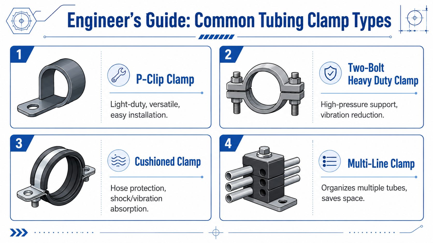
An Engineer's Guide to Common Tubing Clamp Types
Catalogues often make clamp choices look simpler than they are. In practice, clamp geometry affects service life, access, assembly time and how much vibration reaches the rest of the machine.
At a glance clamp type comparison
| Clamp Type | Primary Use Case | Key Advantage |
|---|---|---|
| P-clip clamp | Single-line routing on frames, guards and panels | Simple installation and neat support |
| Saddle or block clamp | Fixed tube runs on power packs and machinery | Strong support and organised routing |
| Cushioned clamp | Areas with vibration, noise or risk of abrasion | Protects the tube or hose surface |
| Multi-line clamp | Parallel tube runs in tight spaces | Keeps multiple lines aligned and serviceable |
| Band clamp or pipe clip | Light retention and general fixing | Fast, economical and widely available |
P-clips for simple single-line routing
P-clips are useful when you need straightforward support for one hose or tube at a time. They’re common on guards, chassis rails and compact assemblies where access is limited. A cushioned version makes more sense where the line will see recurring vibration or where you want to avoid marking the outer surface.
Their weakness is load capacity and consistency in harsher duty. They’re tidy, but they’re not the first choice for heavily loaded hydraulic tube banks or installations where multiple lines need repeatable spacing.
Saddle and block clamps for structured hydraulic layouts
When you’re building a proper hydraulic assembly, block-style clamps are often the better answer. They give the line a defined seat, hold position well and allow cleaner routing across baseplates, manifolds and structural members.
For engineers looking at stocked options such as stainless steel worm clamps for general securing duties, it’s worth remembering that worm-drive clamps and hydraulic tube support clamps do different jobs. A worm-drive clamp secures around a hose or fitting. A hydraulic line support clamp manages routing, movement and structural restraint.
Cushioned clamps where the line needs protection
Cushioned clamps earn their place where movement can’t be eliminated completely. The insert helps absorb shock and stops metal-to-metal contact. That matters on diesel-powered machinery, compact mobile units and any installation mounted close to a vibrating prime mover.
A clamp that stops abrasion today often prevents the leak you would otherwise be chasing in six months.
They aren’t a cure-all. If the spacing is poor or the run is carrying too much unsupported mass, even a cushioned clamp won’t save the layout.
Multi-line clamps for clean, serviceable builds
Multi-line clamps are valuable when several parallel lines need to stay organised. On a crowded power pack, they improve access and help the assembly look intentional rather than improvised. They also reduce line-to-line contact, which is a common source of wear in busy machines.
The trade-off is planning. Once you commit to grouped line support, your routing needs to stay disciplined. Last-minute changes become harder, so these clamps reward careful layout early in the build.
Choosing the Right Clamp Material and Coating
Material choice separates a clamp that lasts from one that only looks acceptable on the bench. In the UK, the operating environment often decides the answer before the catalogue does. Indoor factory equipment, wash-down areas, agricultural machines and coastal exposure all ask different questions of the same clamp.
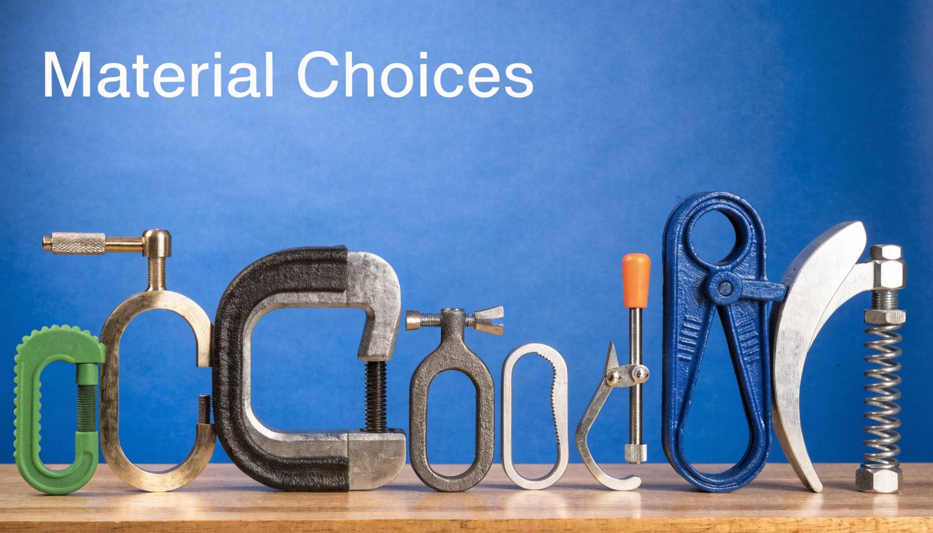
Clamp body materials
Clamps conforming to DIN 3015 Part 1 are standardised for tube diameters from 6 mm to 102 mm and are available in materials including polypropylene and polyamide, with hardware options such as phosphate-treated steel and 316 stainless steel for better corrosion resistance in harsh environments, as outlined by STAUFF’s DIN 3015 Part 1 clamp range.
For day-to-day hydraulic work, the common body material choices usually come down to:
- Polypropylene: A sensible general-purpose option for many industrial installs.
- Polyamide: Often preferred where temperature and chemical exposure are more demanding.
- Elastomer elements: Useful where vibration isolation and noise control matter.
Hardware and coating choices
The body material is only half the decision. Fasteners, weld plates, cover plates and mounting rails often determine how the clamp ages in service.
Use zinc-coated or treated steel where the machine lives indoors and contamination is controlled. Move to stainless hardware when the machine will see weather, salt, wash-down or persistent moisture. That’s often the right call for agriculture, food-related environments and mobile plant that doesn’t spend its life under cover.
If corrosion is a recurring issue in your plant, it’s also worth reviewing broader solutions to stop metal rusting, because clamp failure is often part of a larger surface protection problem rather than an isolated parts issue.
The cheapest hardware usually looks cheapest after the first winter.
Where engineers go wrong
A common mistake is mixing a good clamp body with poor hardware. Another is specifying stainless because it sounds safer, without checking whether galvanic compatibility, mounting surface condition and maintenance practice support that choice properly.
Material selection works best when you ask three plain questions. Is the environment wet or contaminated? Will the machine vibrate heavily? Will anyone want this installation still looking and functioning properly years from now? The answers usually narrow the options quickly.
Correct Sizing and Compatibility for Hydraulic Tubing
Sizing errors are responsible for a lot of clamp trouble. The clamp may fit in the loosest sense, but a fit that only works on the bench often won’t survive pressure changes, temperature cycles and normal machine movement.
Start with the outside diameter
For a clamp for tubing, the first dimension to trust is the outside diameter of the actual hose or tube in service condition. Don’t size from nominal bore and don’t assume a replacement hose matches the old one perfectly. Measure what’s there, including any outer cover that affects the clamp fit.
For optimal clamping force, the hose outside diameter should sit in the middle of the clamp’s specified range. A clamp that’s too large won’t apply even pressure, while one that’s too small can cut into the hose material and compromise integrity at pressures exceeding 200 PSI, as explained in Tork Clamps’ guide to PSI ratings in hose clamps.
A practical way to size correctly
Use this sequence when you’re checking compatibility:
- Measure the actual OD: Use a caliper, not guesswork.
- Check the clamp range: The measured OD should sit around the middle of that range, not at the extreme end.
- Consider hose construction: Soft outer covers, braided hose and rigid tube all react differently to clamp load.
- Think about service conditions: Pressure fluctuation, heat and vibration can expose a borderline size selection very quickly.
What happens when the size is wrong
An oversized clamp tends to create patchy contact. The line can shift, twist or fret against the clamp body. On hose assemblies, that can become a leak path or a wear point.
An undersized clamp creates the opposite problem. It bites too hard, distorts the hose or tube support point and can turn the clamp into the thing that damages the line.
If you have to force the clamp choice to work, it’s the wrong size.
Compatibility also means matching the clamp type to the line itself. Thin-wall tube, flexible hose and coated pipe all need slightly different treatment. Good sizing is never just about whether the part can be tightened.
Managing Vibration in Mobile and Industrial Hydraulics
Vibration is where clamp choice stops being a tidy-routing decision and becomes a reliability decision. A stationary industrial power pack and a machine working across uneven ground don’t ask the same thing from their line supports. If you treat them the same, the mobile machine will remind you why that was a mistake.
Standard series versus heavy series
Professional clamp ranges separate Standard Series from Heavy Series for good reason. Heavy Series clamps are designed for the dynamic stress and high vibration found in mobile machinery, while Standard Series clamps are intended for more moderate vibration in stationary settings. The correct choice affects reliability by reducing hose fatigue and limiting fitting loosening, as shown in the Brennan tube clamp catalogue hosted by Capital Rubber.
In practical terms, use Standard Series where the structure is stable and vibration is predictable. Use Heavy Series where the machine bounces, twists, brakes sharply or runs across rough surfaces. That includes agricultural equipment, materials handling machines and site plant.
Why vibration reaches more than the line itself
Once a tube run starts moving repeatedly, the problem spreads. Pump ports see alternating loads. Valve banks inherit movement they weren’t designed to carry. Fittings loosen gradually rather than dramatically, which makes the fault harder to spot during routine checks.
This is also where hardware choice matters. If you’re comparing support methods for exposed pipework and structures, options such as U-bolt clamps for securing round sections have their place, but they don’t provide the same isolation and controlled support as purpose-selected hydraulic tube clamps.
A visual reference helps when discussing clamp restraint and movement control in assemblies:
Spend the money where motion exists
This is one area where under-specifying usually costs more than over-specifying. If the machine is mobile, if the engine and hydraulic package share a compact frame, or if the operator already complains about noise, invest in the clamp arrangement early. It’s easier to design vibration control in than to retrofit around fatigue failures later.
Installation Best Practices and Key Standards
Even the right clamp can perform badly if it’s installed carelessly. Most clamp problems in service come from poor mounting, poor alignment or fastening practices that preload the line before the machine has even run.
Install the clamp to support, not to pull
A clamp should hold the line in its intended position. It shouldn’t drag a tube sideways to compensate for poor routing. If the line only fits when the installer forces it into place, the assembly already contains stress.
Use a flat, sound mounting surface. Keep the clamp halves square. Make sure the line enters and exits naturally rather than bending sharply at the support point. These basics matter more than people sometimes admit.
Follow standardised dimensions where possible
DIN 3015 Part 1 matters because standardisation improves interchangeability and predictability. As noted earlier, these clamps are standardised for 6 mm to 102 mm tube diameters and are available in body materials such as polypropylene and polyamide, alongside hardware choices including phosphate-treated steel and 316 stainless steel.
That standardisation helps with several practical issues:
- Replacement planning: Parts are easier to identify and source later.
- Build consistency: Installations across multiple machines stay more uniform.
- Maintenance access: Technicians are dealing with familiar sizes and hardware patterns.
For applications that still need conventional clip-style fastening alongside block clamps, stocked items such as a 150 mm jubilee clip for larger diameter retention jobs can complement a build, but they shouldn’t be used as a substitute for proper hydraulic line support where vibration control is required.
Three installation habits that prevent future trouble
- Check clamp spacing: Don’t leave long unsupported runs that allow the line to whip or sag.
- Use the correct fastener torque: Over-tightening can distort components. Under-tightening allows movement.
- Inspect after initial run time: A newly commissioned system often settles slightly once pressure and vibration are introduced.
Good installation leaves the line relaxed, supported and easy to inspect.
A neat build isn’t only about appearance. It usually reflects a system that has been assembled without hidden stress, and that tends to be the system that stays dry and quiet for longer.
Partner with MA Hydraulics for Your Clamping Needs
Choosing a clamp for tubing is really about choosing how much movement, corrosion risk and maintenance burden you’re willing to accept into the system. Diameter matters, but it isn’t the full story. Clamp type, body material, hardware finish, vibration duty and installation quality all affect how the hydraulic package behaves over time.
For engineers specifying new builds, that means looking beyond the line itself. A badly supported pipe run can shorten the life of pumps, valves and fittings that cost far more than the clamp ever will. For MRO teams, it means treating repeat leaks and vibration faults as support problems as often as component problems.
MA Hydraulics Ltd supplies hydraulic components and bespoke power solutions for mobile and industrial applications, including support with component selection, cross-referencing and replacement part identification where the original clamp or fitting is difficult to trace. That matters when you’re rebuilding older machinery, standardising parts across a fleet or laying out a new power pack where space is tight and serviceability matters.
The best results usually come from treating clamping as part of the hydraulic design, not as an afterthought at the end of the build. When the support strategy is right, the whole system tends to run quieter, stay tighter and ask for less attention.
If you need help selecting the right clamp, matching a replacement, or planning line support for a new hydraulic assembly, contact MA Hydraulics Ltd. Phone 01724 279508 today, or send us a message.
