
A 4 bar pressure relief valve is set to relieve at 4 bar (400 kPa), eight times the 0.5 bar UK regulatory threshold, but the label alone doesn't prove it fits your circuit. You must also check the protected component's allowable pressure, the flow the valve can discharge and what happens before it fully opens.
The useful starting point isn't the catalogue entry. It's the pressure zone you need to protect: the cooler, filter housing, pilot gallery, drain line or manifold that would otherwise see excessive pressure.
What a 4 Bar Setting Protects
A 4 bar pressure relief valve protects a zone by opening a discharge path at its specified inlet pressure and sending oil somewhere safer, such as tank or a lower-pressure line. It does not shut the pump down; it gives the excess flow another route.
4 bar relief valve reference figures
| Item | Figure | What it means |
|---|---|---|
| Nominal set pressure | 4.0 bar, equivalent to 400 kPa | Inlet pressure at which the valve is set to relieve |
| Regulatory threshold | Above 0.5 bar | A 4 bar setting is eight times the UK pressure-equipment threshold |
| Typical hydraulic duties | Return, cooler, filter bypass, pilot, case drain | Protects a low-pressure zone, not the main work pressure |
| Units to specify | bar and L/min | Match UK metric pump flow and component ratings |
The threshold in the table comes from HSE's guidance on the Pressure Equipment (Safety) Regulations 2016, which explains that the regulations cover pressure equipment and assemblies with a maximum allowable pressure above 0.5 bar, subject to exclusions. At eight times that threshold, a 4 bar setting still sits in regulated territory even though it is modest for hydraulics, so design, manufacture and conformity need checking against the actual assembly.
Define the protected zone
Start on the schematic and mark every component sharing the same connected pressure until the next restriction or valve: cooler, filter housing, pilot gallery, hose, shaft seal, drain line or manifold. The limiting item is the one with the lowest allowable pressure in that zone, which may be the cooler rather than the manifold, or the seal rather than the hose.
Then test that zone against credible conditions: normal running, cold starting with thicker oil, a blocked return and a foreseeable fault. A nameplate may say 4.0 bar, but cold oil can stiffen a bypass path and a sticking element can delay lift; during that response time, pressure can climb briefly above the opening point before useful discharge begins.
Practical rule: Select the valve around the weakest protected component and the worst credible flow, not around the pressure stamped on the replacement part.
Keep the specification usable
State pressure in bar and flow in litres per minute, commonly written as L/min. Include the fluid, operating temperature range, connection details and intended discharge route so a supplier can assess the actual duty.
Any price comparison should use GBP and compare equivalent assemblies, including bodies, seals and adjustment arrangements. A cartridge price alone is not comparable with a complete inline valve.
The table narrows the search; the zone decides.
How the Valve Opens in Service
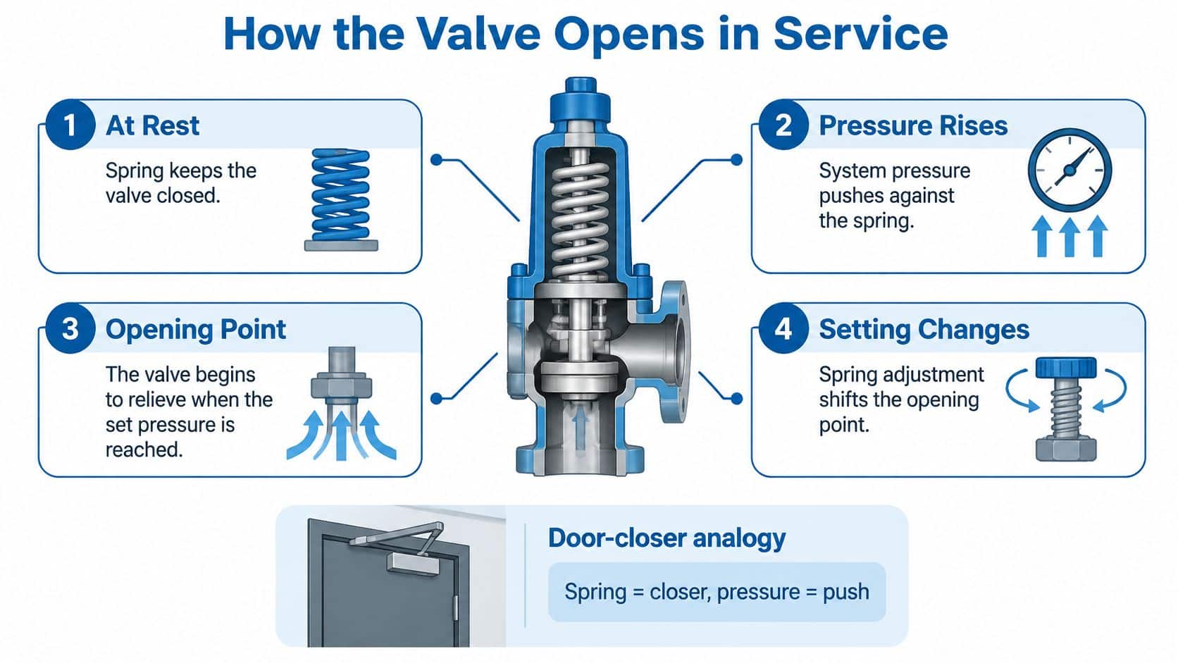
Consider a power pack returning oil through a cooler. While the return path is clear, the relief valve remains shut; when resistance increases, pressure pushes against its closing mechanism.
A door closer provides a useful analogy: the spring is the closer, and pressure is the push. Increasing spring compression usually increases the force needed to start opening, subject to the valve's construction and approved adjustment range.
From a closed seat to useful discharge
At rest, the spring holds the poppet or other closing element against its seat. As inlet pressure rises, the hydraulic opening force increases until the element starts to lift.
That first movement doesn't provide the valve's full discharge capacity. As more oil needs to escape, the valve must open further, and the inlet pressure can rise above the initial opening point.
The resulting pressure rise is commonly described through the valve's pressure override or accumulation behaviour. Read the manufacturer's terminology carefully, because the test conditions and stated flow matter as much as the curve's shape.
A pilot-operated design uses a pilot stage to control the main element and may offer a flatter pressure-flow characteristic. It also introduces pilot passages whose cleanliness, drain arrangements and minimum operating conditions must suit the application.
Allow for the transient, not just the setting
The pressure-equipment essential safety requirements state that pressure-limiting devices must prevent pressure permanently exceeding maximum allowable pressure, with a permitted momentary surge limited to 10%; for a maximum allowable pressure of 4 bar, that means 0.4 bar above it, or 4.4 bar.
That's a regulatory design reference where applicable, not a universal permission to operate above the equipment limit. It doesn't replace the manufacturer's certified tolerance, relieving-capacity information or an assessment of the complete assembly.
HSE's guidance on relief and vent systems identifies relief-valve response times ranging from tenths of a second to more than one second, alongside risks from blockage and trace leakage. In a short oil-filled gallery, continued pump delivery during that delay can produce a sharp pressure rise because hydraulic oil is only slightly compressible.
What changes the opening behaviour
The bench setting isn't the whole service condition:
- Inlet restriction: A small port or long feed line creates pressure loss between the protected component and the valve, potentially causing instability or chatter.
- Outlet back pressure: A shared tank line can change opening and closing behaviour, stability and available capacity.
- Cold oil: Higher viscosity increases line losses and can affect moving-element response.
- Hot oil: Lower viscosity can make internal leakage more apparent.
- Contamination or damage: Dirt and a marked seat can prevent reliable sealing or movement.
- Adjustment condition: A locked adjuster prevents casual changes, but it doesn't prove that the setting is correct.
Gas and liquid duties also need separate assessment. Don't assume that a valve suitable for hydraulic oil has equivalent capacity or behaviour on compressed gas.
Read the manufacturer's curve for opening tolerance and discharge capacity at the intended low-pressure duty. A high headline flow rating at another test condition doesn't establish adequate protection here.
Where 4 Bar Valves Sit on Machines
A low-pressure relief valve can sit beside a much higher-pressure work circuit without protecting that work circuit. Follow its inlet connection and discharge path to understand what it does.
Return lines and filter bypasses
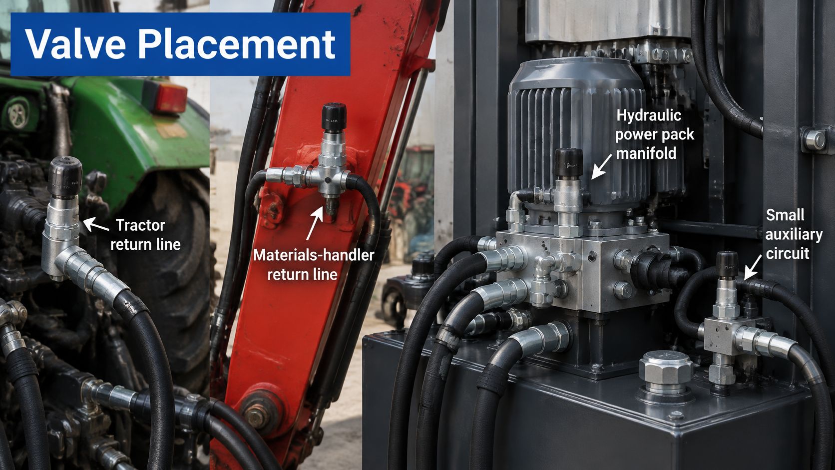
On a tractor or materials handler, a cooler restriction can raise return pressure. A correctly arranged bypass offers an alternative path, protecting the cooler, return hose or connected seal, provided their limits and the discharge arrangement are compatible.
Case drains deserve particular care. A motor's shaft-seal limit may require a lower-pressure, dedicated drain arrangement, so don't connect it to a general return relief because both are described as low pressure.
A filter bypass has a different job. It responds to pressure difference across the element and routes oil around a restriction, which means the relevant setting is generally differential pressure, not just pressure relative to tank.
That distinction matters during fault-finding. A bypassed filter may preserve oil supply while allowing unfiltered oil downstream; it doesn't regulate the main pump outlet or remove the need to replace a clogged element.
Pilot galleries and small manifolds
A pilot gallery feeding a CETOP directional valve may use a small relief to limit control pressure. Check the directional valve's actual pilot requirements, because the mounting pattern alone doesn't establish a suitable pilot setting.
In a low-pressure lubrication manifold or suitably designed clamp circuit, the relief protects that local zone. The threatened part might be a pilot cap, small-bore hose or manifold accessory rather than the main actuator.
These arrangements appear on mobile plant, agricultural machinery and factory power packs. Mini power packs can also contain a low-pressure stage alongside a separate work stage, so trace the internal passages rather than assuming the whole assembly shares one limit.
A relief valve protects the zone connected to its inlet. It doesn't make a weaker downstream component safe merely by being nearby.
Pressure relief also isn't a cure for pump cavitation. For that separate failure mechanism, Intech Corporation's discussion of how to fight hydraulic cavitation with polymer impellers provides context on material choices and wear, rather than a substitute for checking inlet conditions.
On the schematic, ring the intended protected zone. Confirm that the valve inlet lies inside it and that every included component can withstand the assessed relieving pressure and transient.
Choosing a 4 bar valve by duty
Start with the duty, then compare the setting, flow requirement and failure consequence. A valve that suits a small control gallery may be entirely unsuitable for diverting full pump delivery.
Choosing a 4 bar valve by duty
| Duty | Set-pressure check | Flow check | Watch-out |
|---|---|---|---|
| Filter or cooler bypass | Just above clean pressure drop and below element or cooler limit | At least full pump delivery in L/min | Excessive spring loading can leave a blocked element exposed to damaging pressure |
| Case drain or low-pressure return | Below shaft-seal and hose rating | Case leakage plus cold-start transient | Tank-line back pressure moves the real opening point |
| Pilot or control gallery | Match the pilot cap, often near the intended low-pressure setting | Small flow and a fast response | A large work-port valve may be too big or unsuitable dynamically |
| Thermal or blocked-section relief | At or below the zone maximum allowable pressure | Enough for expansion and any credible pump slip | Parts rated under the transient remain unprotected |
Read each row against the actual circuit
For a filter or cooler bypass, establish the clean pressure drop under the most demanding normal condition. The operating margin must avoid nuisance bypassing without allowing the protected component to exceed its limit.
For a case drain, work from the motor or pump manufacturer's permitted drain pressure. Include the return route, not just the valve, because a restrictive hose can undermine an otherwise appropriate selection.
A pilot circuit needs stable control and suitable response at its small flow. A physically larger valve isn't automatically safer, particularly if its minimum controllable flow or low-pressure behaviour is unsuitable.
Thermal relief protects trapped liquid against expansion. If a pump can continue feeding that section, assess that delivery separately rather than treating it as a thermal-only duty.
Check materials and examination requirements
HSE's pressure-systems guidance explains that most pressure systems require a written scheme of examination prepared or certified by a competent person, covering protective devices, pressure vessels and potentially dangerous pipework. Establish which requirements apply to the particular assembly rather than assuming every hydraulic circuit has identical obligations.
Before ordering, check:
- Fluid compatibility: Confirm seals and seat materials for mineral oil, water-based or biodegradable fluids.
- Temperature range: Include cold starting and the hottest credible return condition.
- Connections: Check thread form, cavity, port size and pressure-loss implications.
- Protection role: Establish whether you need a circuit relief or a safety accessory with appropriate conformity documentation.
Use the pressure relief valve sizing guide to organise the flow and pressure information. Reject a nameplate-only match if the supplier can't confirm capacity, tolerance and suitability for your stated fluid and duty.
How to Install the Valve Safely
Installation determines whether the valve senses and relieves the pressure that threatens the component. A suitable part can still provide inadequate protection if an isolating valve, restrictive passage or blocked outlet separates it from the duty.
HSE's pressure-systems approved code of practice says plant capable of exceeding its safe operating limit should have suitable pressure-relieving or pressure-limiting protection, installed as close as practicable to the protected item, with discharge arranged safely.
Fitting and commissioning sequence
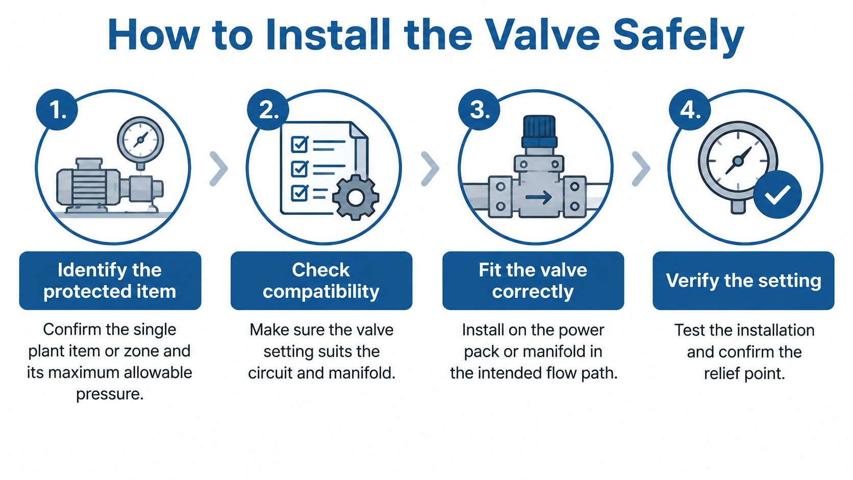
Only competent personnel should fit and commission pressure-protection devices. Isolate the machine, release stored pressure and secure loads before opening the circuit.
-
Identify the protected item. Mark its allowable pressure and assessed transient on the schematic. This prevents a valve being assigned to a zone containing an unsuitable component.
-
Mount close to the pressure source being protected. Connect the inlet to the intended pressure side through a short, direct path. Don't leave an isolating valve between the relief and protected item unless the engineered arrangement preserves protection.
-
Size both connections for relieving flow. Check the manifold passages as well as the visible hoses. A generous valve port won't compensate for a restrictive drilling upstream.
-
Provide a safe discharge route. Return oil to tank or another approved destination that can accept the flow. Never discharge into a dead leg or a section unable to withstand the resulting pressure.
-
Check outlet pressure in service. Where the tank line is shared, measure its pressure during simultaneous machine functions. Account for the valve design's sensitivity to back pressure rather than assuming the outlet is pressure-free.
-
Prove and secure the setting. Use a suitable calibrated gauge at the valve inlet and the manufacturer's commissioning procedure. Lock the adjuster and record the verified setting, date, test conditions and protected item.
-
Check the complete zone. Confirm that gauges, hoses, fittings and downstream manifolds tolerate the assessed conditions. Provide separate protection where another section has a lower safe limit.
-
Control hot-oil discharge hazards. Prevent spray towards operators and route the return securely. Use a submerged tank return only where the equipment manufacturer permits it, accounting for aeration and back pressure.
Verify the flow path before running
Follow the body arrows and port markings, then compare the fitted assembly with the schematic. Cartridge cavities and externally similar inline bodies aren't necessarily interchangeable.
The hydraulic installation guidelines provide a useful framework for checking connections and assembly practice. Commission under controlled conditions without deliberately exposing a vulnerable component to an unproven relief setting.
Installation check: Trace an uninterrupted path from the protected item, through the relief valve, to a discharge destination that can accept the flow safely.
A correctly selected valve still fails the system if it's fitted backwards, too far from the protected item or with nowhere for the oil to go.
Maintenance and Periodic Checks
Keep a protection record that identifies the valve, its verified setting, the protected item and that item's maximum allowable pressure. Include rated discharge capacity against maximum pump or process delivery in L/min, together with the fluid and test conditions.
Where a written scheme applies, include the relief device within its scope and follow the competent person's examination requirements. Don't invent a universal service interval: contamination, duty cycle, environment and the consequences of failure all affect the inspection plan.
Inspect without creating a new hazard
A setting test must follow an approved procedure with suitable containment and instrumentation. Don't dead-head an unfamiliar circuit just to see whether the valve opens.
- Measure opening behaviour: Compare inlet pressure against the recorded acceptance limits using a calibrated instrument.
- Inspect the flow path: Look for blockage, corrosion, external leakage and changes to the discharge arrangement.
- Check adjustment security: Investigate broken seals, moved locknuts or evidence of unauthorised adjustment.
- Repair deliberately: Inspect a leaking seat and replace service parts or the complete valve as the manufacturer permits.
Select a hydraulic pressure gauge with a range and resolution suited to low-pressure testing. A gauge intended for the main work circuit may not show small deviations clearly enough.
Symptom and first check
| Symptom | Likely cause | First check |
|---|---|---|
| Valve chatters | Pressure drop from a small or long inlet line | Assess shortening the inlet and enlarging the port |
| Opens above its setting in service | Back pressure from a shared tank line | Measure outlet pressure |
| Dribbles or never opens | Dirt, damaged seat, sticking mechanism or incorrect locked adjustment | Inspect the seat and check adjustment security |
| Pressure stays above allowable limit | Slow response or undersized valve | Stop and investigate; don’t wind down the spring |
Treat these as starting points, not definitive diagnoses. Chatter can also involve unsuitable valve dynamics, while leakage may come from contamination elsewhere in the assembly.
If pressure remains above the allowable limit, stop and investigate. Winding the spring down to hide the symptom can create nuisance relieving without correcting inadequate capacity, restricted discharge or an unsuitable installation.
Confirm the Valve Before You Order
Accept the valve only when the engineering evidence supports the complete installation. The replacement should restore a defined protection function, not merely resemble the part removed.
The acceptance checks
Use these conditions to make the decision:
- The zone is suitable: Every protected component can withstand the selected setting and assessed short transient within its applicable limits.
- The capacity is adequate: Verified relieving performance covers the maximum credible pump or process delivery at the permitted pressure.
- The installation works: The inlet senses the protected zone directly, and the outlet has a safe, adequately sized discharge path.
- The setting is demonstrable: A controlled gauge test confirms the intended behaviour, and the adjustment can be secured against unintended change.
If any condition fails, change the valve, pipework or protection arrangement before the machine runs. Don't assume that increasing a component's nominal rating alone resolves response or discharge problems.
Specify the replacement completely
For a replacement cartridge, record the cavity designation, thread, seals and any pilot or drain connections. For an inline body, identify the port thread, flow direction and mounting arrangement.
A manifold valve also needs the circuit function and internal passage arrangement confirmed. Photographs help with identification, but they don't replace a schematic or the manufacturer's part information.
Send the supplier the required setting, maximum flow, fluid, temperature range, outlet conditions and protected component limits. State whether the adjuster must be tamper-resistant and whether conformity documentation is required for the intended safety role.
The right purchase is a valve whose documented behaviour fits the zone. The nearest catalogue pressure is not enough.
MA Hydraulics Ltd supplies hydraulic valves, components and bespoke power packs, with application support to help match a low-pressure relief valve to its protected circuit. Phone 01724 279508 today, or send us a message with the required set pressure, flow in litres per minute and a photo of the nameplate so the team can help identify a suitable replacement or assembly.
