
The pump's noisy on the first start, the oil looks clean, and someone suggests fitting a finer screen to keep more dirt out. Before you order it, check the pressure at the pump inlet. The strainer installed to protect the pump may already be restricting its supply, and a finer replacement could make that restriction worse.
Choosing Y type strainers means balancing debris capture against available pressure, fluid viscosity and maintenance access. Pipe size alone won't settle it. You need a screen that intercepts damaging debris without making the pump work against an inlet restriction, particularly when the oil's cold.
Mesh Sizes and Specifications for Y Type Strainers
A Y type strainer is an inline filter with a Y-shaped body, an angled screen in the flow path and a removable cap that allows the screen to be withdrawn for cleaning. Its job is to stop unwanted solids reaching equipment, not to deliver every level of cleanliness a hydraulic circuit might require.
Start with the debris you need to intercept. A coarse screen offers less restriction but lets smaller particles through; a finer screen captures smaller debris but generally needs more area, more pressure allowance or more frequent cleaning.
Match the opening to the duty
Mesh grades, approximate openings and typical duties
The following are indicative selection examples, not guaranteed aperture specifications. Wire diameter and screen construction affect the actual opening, so order against the manufacturer's stated aperture rather than mesh count alone.
| Mesh count | Typical duty |
|---|---|
| 20, approximately 0.84 mm openings | Illustrative coarse-debris protection ahead of pumps, subject to the pump manufacturer’s inlet requirements |
| 40, approximately 0.42 mm openings | Illustrative general process-pipework duty where coarse capture is sufficient |
| 60, approximately 0.25 mm openings | Illustrative protection for control valves and meters, subject to their contamination tolerance |
| 100, approximately 0.15 mm openings | Illustrative finer screening where adequate pressure allowance and screen area are available |
| 500, approximately 0.025 mm openings | Water-service screens, such as the DZR-brass model evaluated below; confirm its actual aperture before specifying |
Don't treat those duties as automatic approvals. A meter may need finer protection than a particular screen provides, while a pump inlet may not tolerate even a relatively coarse screen in a small body. The equipment manufacturer's requirements take priority.
Practical rule: Specify the opening needed to stop damaging debris, then check whether the complete strainer can pass the required flow.
Choose compatible materials and clear units
Cast iron and carbon steel are options for suitable industrial and hydraulic duties, but neither material label proves compatibility with the fluid or pressure cycle. Stainless steel may suit corrosive or water-contact applications where the specific grade and approvals are appropriate. DZR brass is used for water fittings, commonly with a stainless-steel screen.
Check seals as carefully as the body. A compatible metal body with an unsuitable gasket still makes an unsuitable assembly.
Use millimetres, bar, litres per minute and degrees Celsius on the enquiry. The UK Government's guidance on measurement markings explains that metric measurements must be more prominent where supplementary imperial measurements are used in regulated trade.
Identify the duty, choose the appropriate mesh row, then use the hydraulic filter selection guide to decide whether you also need a dedicated hydraulic filter.
Sizing by Kv and Pressure Drop
A DN25 connection can still impose too much restriction at the required flow. Nominal pipe size identifies the connection, not the strainer's flow capacity. Kv relates flow to pressure drop: at the same flow, a lower Kv means a higher pressure loss.
The Essco EV1540 technical specification lists Kv values of 4.5 m³/h for DN15 and 35 m³/h for DN50. The model is rated PN16, has a 0–85°C operating range, female BSP connections and a 500-mesh stainless-steel screen in a DZR-brass body.
Published Kv values for the referenced water-service model
| Nominal size | Kv (m³/h) | Check before selecting |
|---|---|---|
| DN15 (1/2 inch) | 4.5 | Check pressure drop at maximum flow, not only at the normal operating point |
| DN50 (2 inch) | 35 | Check that the pressure drop remains within the system allowance at required flow |
Work the calculation against actual flow
For water, use:
Δp in bar = (Q ÷ Kv)², with Q in m³/h.
Convert flow from litres per minute to cubic metres per hour before calculating.
Consider three hypothetical operating points:
- Modest flow through the smaller body: At 33.3 litres per minute, or 2 m³/h, the calculated loss is (2 ÷ 4.5)², approximately 0.20 bar. That may suit a pressure-fed water circuit, but it can be unacceptable on pump suction.
- Higher flow through the larger body: At 333.3 litres per minute, or 20 m³/h, the calculated loss is (20 ÷ 35)², approximately 0.33 bar.
- The same high flow through the smaller body: At 20 m³/h, the calculated loss is (20 ÷ 4.5)², approximately 19.75 bar. This rules out that selection; it does not mean the strainer can operate beyond its pressure rating.
Allow for the complete operating envelope
Check whether the published Kv includes the supplied clean screen. If it does, do not add the clean-screen loss a second time. If the value describes the body alone, obtain the screen-element loss separately.
Reserve pressure allowance for debris accumulation. A strainer that uses the full permitted pressure drop when clean leaves no margin as the screen loads.
For oil, check viscosity corrections and manufacturer curves before using the water equation. Cold-start viscosity can increase pressure loss, while the resulting inlet restriction can reduce available net positive suction head or violate the pump manufacturer's inlet-pressure requirement. A finer mesh may capture smaller debris, but its added restriction can make that protection the source of pump starvation.
For cold-water supplies, check BS EN 806, water-contact suitability and product approvals. The standard is an installation reference, not a substitute for product approval. A PN rating alone does not establish suitability for every temperature, fluid or transient.
How a Y Type Strainer Works and How to Install It
Think of a tea strainer held at an angle inside a pipe: the liquid passes through while the leaves remain behind. A Y type strainer applies that principle inside a pressure-containing body, with the screen supported and sealed so the intended flow passes through its openings.
This cutaway illustrates the relationship between the flow passage, angled screen and debris pocket.
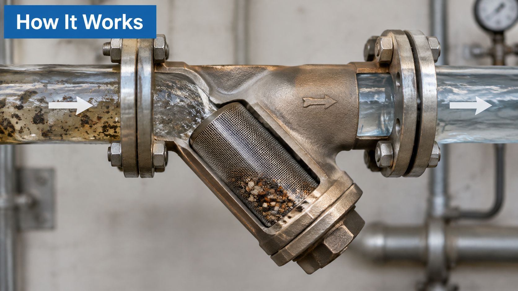
Fluid enters the body, passes through the screen and leaves through the outlet. Retained solids remain in the screen chamber, with their collection pattern affected by the body design, orientation and flow. During maintenance, the cap and screen can usually be removed without taking the body out of the pipework.
Protect the component without confusing screening and treatment
Consider a skid carrying a pump, control valve, meter and heat exchanger. Rust flakes, jointing debris or fragments left during assembly can obstruct small passages or damage working surfaces. A strainer can intercept that larger debris before it reaches vulnerable equipment.
Make a component-by-component list:
- Gear and vane pumps: Check whether inlet screening is permitted, and establish the allowable inlet restriction.
- Control valves and flow meters: Identify small passages and any manufacturer-specified upstream protection.
- Heat exchangers and dosing equipment: Check passages that could plug and access needed for recovery.
- Skid manifolds: Account for debris introduced during machining, assembly and connection work.
A grain-of-sand-sized particle is a useful thought experiment: which component would it jam, score or block? It isn't a cleanliness specification, but it helps identify where protection matters.
Screening is protection, not treatment. Capturing larger particles doesn't prove that water is suitable for use or that hydraulic oil meets a component's cleanliness requirement. The Drinking Water Inspectorate's triennial report places particulate and turbidity control within a wider treatment and distribution framework.
Install for the person who has to service it
Start with the manufacturer's permitted mounting positions. Don't assume a body approved for horizontal installation is equally suitable in every vertical arrangement, and check the cast flow arrow before tightening the connections.
Then work through the physical installation:
- Screen withdrawal space: Leave enough clearance along the cap axis to remove the complete screen, not merely loosen the cap.
- Isolation and drainage: Provide suitable upstream and downstream isolation and a controlled low-point drain. Account for trapped pressure and possible backfeed.
- Pressure measurement: Fit accessible test points on both sides so differential pressure can be measured at the same operating condition.
- Air removal: Provide a safe vent where the arrangement can trap air, using fittings compatible with the service.
- Pipe support: Support adjacent pipework independently. Don't use the strainer body to pull misaligned pipes into position.
- Seal identification: Record the gasket material and part reference so maintenance staff don't have to guess later.
A compact installation isn't maintainable if the screen can only be removed after dismantling the skid.
The following installation video should be used alongside the product instructions, not instead of them.
For instructional use, check that the player retains its proportions and that captions accurately identify the components and actions. The GOV.UK video publishing guidance recommends checked captions and an accompanying transcript; flow arrows, labels and isolation actions should also be explained in text rather than left to visuals alone.
At commissioning, record clean differential pressure at normal and peak flow, together with fluid temperature. Label those readings as the baseline so the next engineer can compare like with like.
How to Clean a Y Type Strainer Without Contaminating the System
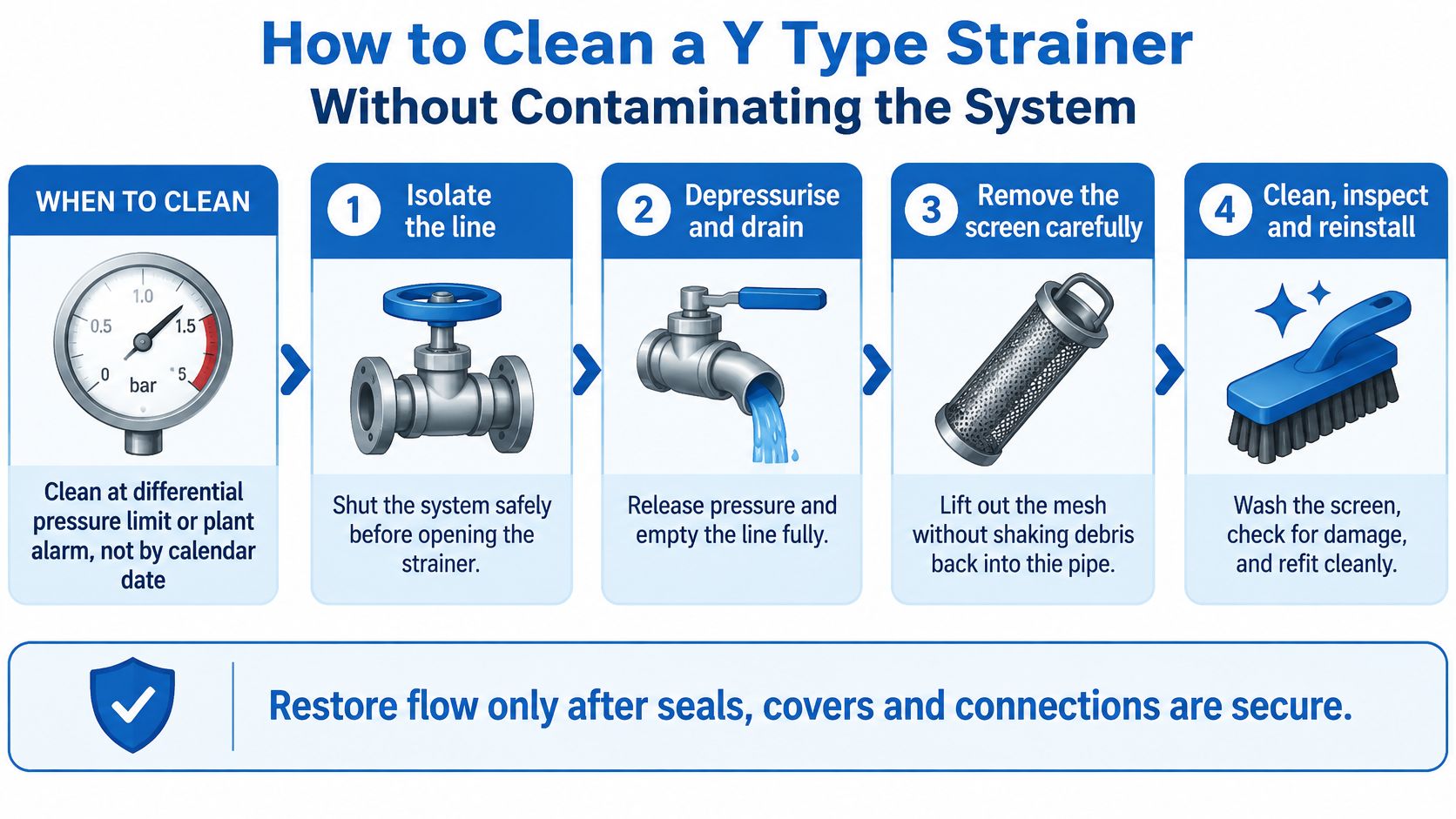
Clean when differential pressure reaches the manufacturer's limit or a defined plant alarm. A calendar inspection remains useful, but it shouldn't be the only protection against an unexpectedly loaded screen.
The Drinking Water Inspectorate's maintenance guidance calls for preventive maintenance, regular filter cleaning and competent personnel following manufacturer instructions. Apply that discipline to the whole job, including isolation, handling and return to service.
Use a controlled cleaning sequence
-
Isolate and depressurise the line. Stop the equipment, secure the isolation points and verify that pressure has been released. Include accumulators, trapped sections and possible backfeed in the isolation assessment.
-
Drain into a labelled container. Capture the body contents through the intended drain point. Keeping the fluid contained prevents spills and lets you examine it for unusual contamination.
-
Remove the cap and withdraw the screen carefully. Keep the opening protected and avoid tipping collected debris into the clean side. Use a clean tray rather than putting the element on the floor or bench beside grinding work.
-
Inspect before washing. Look for torn mesh, deformation, corrosion and damaged end supports. Examine the seal and seating surfaces, since cleaning won't repair an element that no longer seals correctly.
-
Clean using a fluid-compatible method. Use suitable cleaning fluid and a soft brush where permitted. Rinse away loosened debris and dry as appropriate for the service, without introducing lint, moisture or dirty workshop air.
-
Replace damaged seals and refit correctly. Use the specified gasket, seat the screen properly and tighten the cover to the manufacturer's procedure. Extra tightening isn't a remedy for the wrong seal.
-
Refill, bleed and prove performance. Restore flow gradually, check for leaks and record post-cleaning differential pressure at a comparable flow and temperature. A reading that remains high needs investigation before the equipment returns to normal duty.
The graphic summarises the workflow; use the detailed sequence and equipment-specific procedure for the actual job.
Control waste and prove the result
Use the site's permit-to-work arrangements where required, with competent personnel for pressurised and potable-water systems. Store drained fluid in compatible, closed containers and dispose of it through the site's waste-classification procedure. Don't return dirty drainings to the reservoir.
For broader element-handling precautions, the hydraulic filter cleaning guide helps distinguish cleanable screens from elements that should be replaced.
HSE guidance on fluid-system maintenance supports regular blockage checks and attention to fluid condition. Visible cleanliness isn't hydraulic cleanliness: ISO 4406 cleanliness assessment uses particle counts at 4, 6 and 14 micrometres, so neither clear-looking oil nor a washed screen proves that the circuit meets its particle-count target.
Why a Finer Mesh Can Starve Your Pump
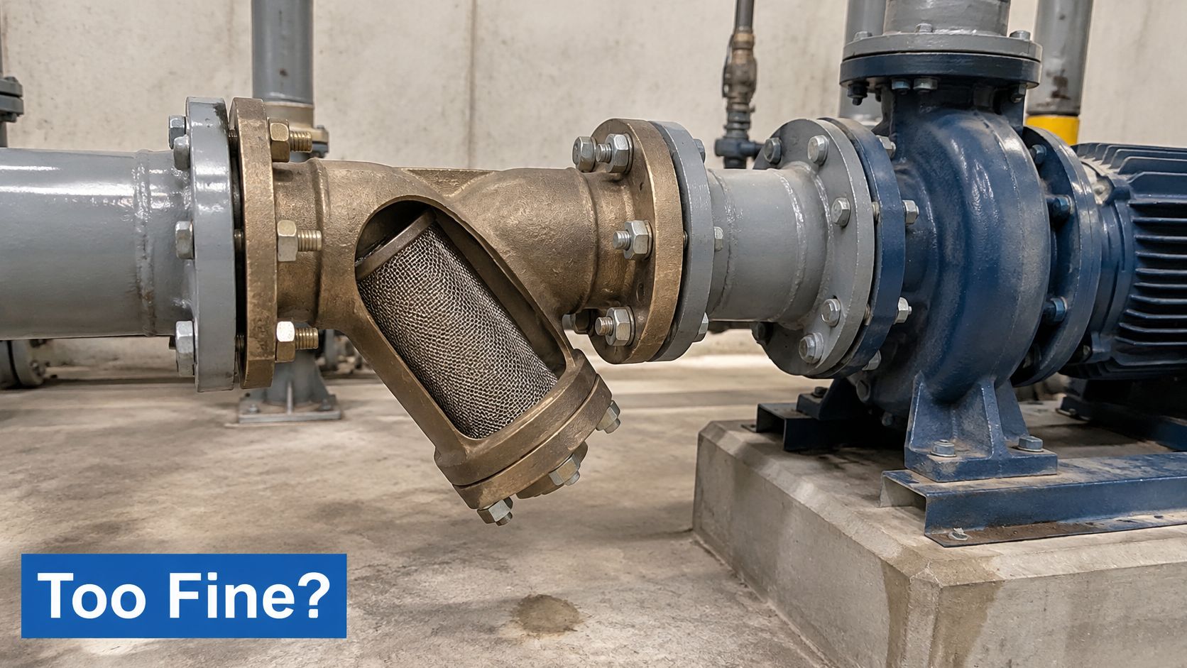
A finer screen can increase the risk of pump damage rather than reduce it. At the inlet, restriction reduces the pressure available to fill the pumping chambers. If inlet conditions fall outside the pump's limits, noise, poor delivery and cavitation can follow.
The government machinery and power-systems guidance stresses hydraulic-system cleanliness, including the work area and tools. Achieving that cleanliness doesn't justify ignoring the pressure needed to supply the pump.
The installation below shows why the strainer must be assessed as part of the inlet arrangement, rather than as an isolated accessory.
Test the cold condition, not just the warm circuit
Cold oil resists flow more strongly than warm oil. A circuit that runs acceptably after warming may suffer excessive inlet depression during starting, particularly with a fine or partly loaded screen.
As a hypothetical comparison, a 500-mesh screen in a compact suction body could starve a pump, while an appropriately sized 40-mesh arrangement could provide coarse protection with less restriction. Neither mesh count guarantees success: screen area, flow, oil viscosity and the pump's permitted inlet conditions decide the result.
Use suction protection for permissible coarse-debris interception, pressure-line filtration to protect downstream components, and return-line filtration to capture contamination before oil returns to the tank. A Y type strainer shouldn't be expected to deliver the cleanliness sensitive hydraulic components need.
Choose the least restrictive inlet protection the pump manufacturer permits, then achieve the required cleanliness with dedicated filtration.
Diagnose before changing the mesh
Symptoms, likely causes and first actions
| Symptom | Likely cause | First action |
|---|---|---|
| Rising differential pressure | Screen loaded with debris | Clean the screen and log pressure before and after |
| Pump noise or cavitation on suction | Restricted screen or undersized body | Check Kv and mesh against flow, then inspect and clean |
| Flow falls after cleaning | Mis-seated screen, obstruction or air leakage at a disturbed gasket | Inspect screen seating and seals; replace damaged parts |
| Cold-start pressure spike or excessive inlet depression | Viscous oil passing a restrictive screen | Verify cold-condition losses; assess a coarser permitted screen or higher-capacity body |
A torn screen can allow debris bypass, but bypass alone doesn't explain falling flow. Check the consequences of the maintenance work rather than assuming every fault is another blockage.
Monitor pressure on both sides, define an alarm against the pump's limits and record cold-start behaviour. The guide to pump cavitation causes provides further checks when inlet restriction isn't the only suspect.
Confirm Your Specification Before You Order
Build the enquiry around the operating duty, not a photograph of the threaded connection. A replacement that screws into place can still have the wrong screen, seal material or flow capacity.
Put the operating information first
- Duty and fluid: State whether the assembly serves hydraulic oil, water or another process fluid. Include the oil grade or fluid identification.
- Normal and maximum flow: Include intermittent demand and starting conditions, not just the usual running flow.
- Temperature and pressure class: Give the cold-start and operating temperatures, working pressure and relevant transients.
- Connection standard and size: Identify BSP or another thread standard, flange details and nominal metric size.
- Body and seal materials: Specify compatibility requirements rather than choosing by appearance.
- Screen specification: Give the mesh count, aperture where known, construction and permitted pressure loss.
- Standards and approvals: Identify cold-water installation requirements and any water-contact approval needed.
- Orientation and access: Include the intended mounting position and measured screen-removal clearance.
- Scope of supply: Say whether you need a replacement screen, seal kit or complete assembly.
Match replacement elements by reference
Use the body manufacturer and part reference to identify a replacement screen. Outside diameter alone won't confirm length, end geometry, support construction or sealing arrangement.
If the identification plate is missing, provide clear photographs of the body markings, cap, connections and removed element alongside measured dimensions. Keep any surviving part numbers, even if they're incomplete.
For an older installation, include the reason for replacement. Repeated blockage, cold-start noise or damaged screens may justify a specification review rather than another identical part. A complete enquiry lets the supplier check compatibility and availability without guessing at the conditions inside the circuit.
MA Hydraulics Ltd, based in Scunthorpe, supplies hydraulic components and bespoke power solutions, with support for matching strainers and replacement screens, cross-referencing older parts and sourcing hard-to-find items. Visit MA Hydraulics Ltd, phone 01724 279508 today, or send us a message with your flow, pressure, temperature, connection size and fluid so the team can help confirm the right specification.
