
You've got the pack installed, the hoses are on, the cable tray is dressed, and someone is asking when they can switch it on. That's usually the point where a hydraulic commissioning job either stays controlled or starts getting expensive.
With hydraulics, first power-up isn't a formality. It's the first moment when contamination, trapped air, wrong rotation, poor pipe support, bad valve settings, or a simple wiring error can turn into damaged pumps, unstable motion, overheated oil, or a safety incident. That risk is even sharper on industrial and mobile machinery because the system isn't just providing a building service. It's creating force, motion, and stored energy.
Generic commissioning guidance is useful up to a point. It helps with discipline, records, and staged sign-off. But hydraulic commissioning procedures need a more hands-on approach. You need to know what to inspect, what to isolate, what to test first, what pressure should stay backed off, and what absolutely must not be assumed.
Why Rigorous Commissioning Is Not Optional
Commissioning is often treated like the last item on the job sheet. In practice, it's a quality-assurance process that proves the installed system matches the design intent and operating requirement. In UK building practice, commissioning is recognised as a staged process rather than one final test, and guidance describes it as beginning in the predesign phase and continuing through post-occupancy verification, with preliminary and final reports closing the loop in a documented way, as outlined by the Whole Building Design Guide on building commissioning.
That lifecycle thinking matters in hydraulics. A hydraulic power pack isn't commissioned properly because the motor runs and the pressure gauge moves. It's commissioned when the pack, controls, pipework, actuators, interlocks, and operating sequence have all been checked, proven, recorded, and handed over in a condition the site team can maintain.
Building commissioning and machine commissioning are not the same
A building-services view of commissioning tends to focus on documentation, controls, and handover discipline. That's useful. But an engineer standing in front of a hydraulic press power unit, a mobile tipping pack, or a bespoke manifold assembly has a different problem set.
You're not just checking whether a system turns on. You're checking things such as:
- Pressure containment under real load
- Pump inlet conditions so a Vivoil gear pump doesn't start its life aerating oil
- Valve settings that won't shock a cylinder or stall a motor
- Return-line and case-drain routing where relevant
- Operator behaviour at start-up, because misuse on day one can undo careful assembly
The cost of getting casual
In broader commissioning practice, total building commissioning is often a small portion of the total project cost. A commissioning guide used in practice notes 0.75% to 3.0% of construction cost for total building commissioning, with basic mechanical commissioning around 3.0%, electrical commissioning around 1.5%, and more complex facilities such as laboratories at 3.5% to 4.0% according to the Wilco commissioning guide. The lesson is straightforward. Commissioning is a relatively small spend compared with the cost of poor performance, rework, and weak handover.
Practical rule: In hydraulics, every mistake is cheaper to find with the system de-energised than with hot oil at pressure.
A disciplined commissioning procedure protects the pack, the machine, and the people around it. It also protects the next engineer who has to maintain it six months later.
Pre-Commissioning Checks The Foundation of Success
Most hydraulic start-up failures begin before any power is applied. Something is loose, something is dirty, something is set wrongly, or something was assumed. Pre-commissioning is where you stop that chain.
UK commissioning guidance commonly treats commissioning as a structured process that starts before site work, including team formation, owner's project requirements, documentation control, and training needs, as described in the five-stage commissioning process. On hydraulic projects, that same discipline shows up as proper drawings, a punch list, fluid specification, valve schedule, test plan, and clear authority over who may alter settings.
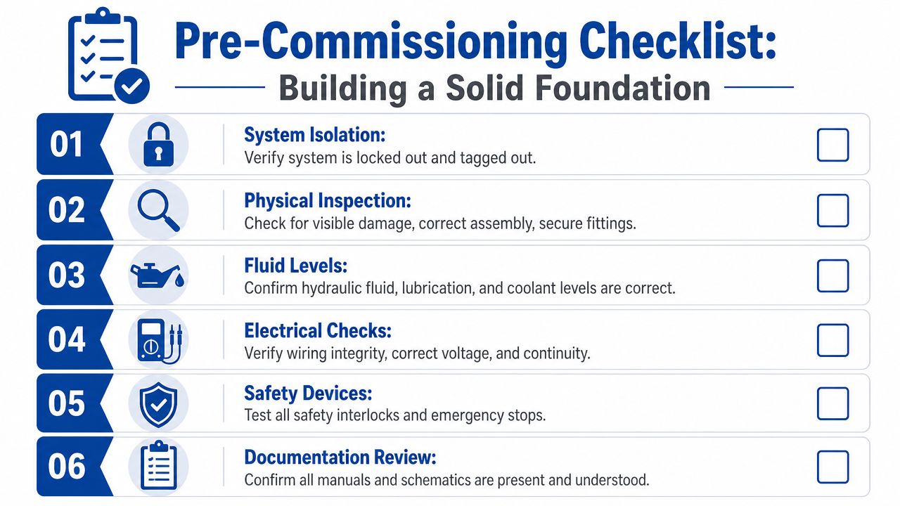
Mechanical checks that catch expensive errors
Walk the system slowly. Don't start with the control panel. Start with your eyes and hands.
- Mounting and support: Check the reservoir, motor, bellhousing, coupling, manifold blocks, filters, coolers, and pipe clamps are secure. A loose suction line support can become a recurring air-ingress problem.
- Hose and tube routing: Look for twist, rubbing points, tight bend radius, poor clip spacing, and unsupported weight at fittings. Pay attention to drains and returns. They're often treated as secondary lines until they fail.
- Component orientation: Confirm filters, check valves, pressure controls, flow controls, and coolers are installed in the correct direction. A wrongly orientated inline valve can waste hours in fault-finding.
- Guarding and access: Rotating couplings, fan sets, and exposed shafts need guarding in place before live testing starts.
If you're commissioning a compact Hydronit power pack, this stage is still just as important. Small packs are less forgiving than people think. A tiny suction issue or wrong relief setting can show up very quickly as noise, heat, or poor motion.
Never assume factory settings are correct for the final machine. Factory settings may be safe defaults for transport or bench test, not the actual installed duty.
Fluid and cleanliness checks
Hydraulic components don't care how tidy the skid looks. They care whether the oil is correct and clean.
Check the fluid specification against the design file and component requirements. Then verify what went into the tank. Don't accept “hydraulic oil” as an answer. Viscosity grade, compatibility, and cleanliness matter, especially on systems with proportional valves, tight-clearance pumps, or fine filtration.
Before first circulation, inspect:
- Reservoir cleanliness
- Breather condition
- Suction strainer or suction arrangement
- Return filter element fitted correctly
- Fill point discipline
- Sample points if provided
If contamination control has been left vague during installation, sort it before energising. MA Hydraulics has a useful page on hydraulic contamination control that aligns with the practical reality of keeping new systems clean from assembly through handover.
Electrical checks before any live hydraulic test
A hydraulic fault is often an electrical fault in disguise. Verify power supply, control voltage, terminal tightness, earth continuity, overload settings, sensor wiring, and solenoid identification against the latest schematic.
On three-phase packs, check motor rotation direction before coupling load is applied where the arrangement allows it. On solenoid valves, confirm each output energises the intended coil and that the coil label matches the drawing. Misidentified coils are common on site modifications and panel retrofits.
Use a simple sign-off list and mark who checked what. It sounds basic because it is. Basic discipline prevents most preventable start-up damage.
The Stepwise Commissioning Sequence
The safest commissioning procedures bring the system up in the lowest-energy state possible, then increase risk one controlled step at a time. That sequence matters more than speed. A rushed first run can turn a minor snag into a damaged pump or bent actuator.
A robust process for industrial equipment includes planning, test documentation, pre-commissioning activities such as cleaning, flushing, leak testing and bump testing, then dry commissioning, wet commissioning, and a slow power ramp-up, with the warning that shipping and installation defects can invalidate earlier factory checks, as described in this step-by-step commissioning process guide.
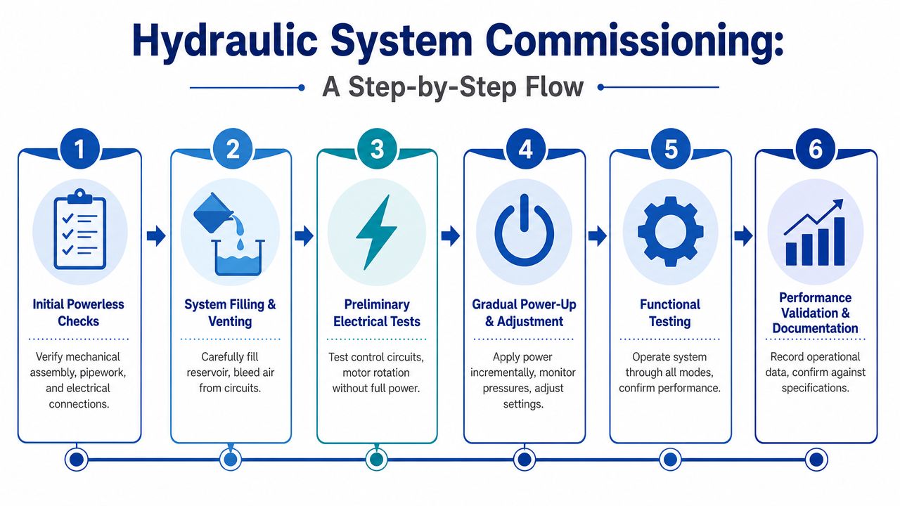
Stage one with no hydraulic power applied
Start locked off. Confirm all earlier checks are signed, all loose tools are cleared, all temporary transport blanks are removed, and all required blanks for flushing or isolation are in the correct places.
At this point, I'd also confirm three practical items that often get missed:
- Gauge availability so you're not commissioning blind.
- A safe venting plan for cylinders, motors, and high points.
- A valve settings register so every adjustment is recorded and reversible.
If the machine is complex, sketch the intended sequence before energising. A quick flow map is often enough. For teams documenting logic and sequence clearly, Mermaid docs-as-code examples are a useful reference for creating readable commissioning flow diagrams that maintenance staff can follow later.
Stage two filling, venting, and low-risk electrical checks
Fill the reservoir carefully through proper filtration. Don't pour from an open drum into an open tank and then wonder why the return filter is carrying the whole installation.
Then vent likely air traps. That may include cylinder ports at high points, pressure lines to gauges, pump housings where applicable, and any remote mounted valve stations. The exact method depends on the circuit, but the principle doesn't change. Get oil to every part of the circuit without creating a high-energy event.
For electrically driven packs:
- Bump the motor briefly to confirm direction.
- Test control outputs without full machine movement where possible.
- Verify interlocks and emergency stop response before pressure build.
Stage three first circulation and flushing
Once rotation is confirmed, start with pressure controls backed off where the design permits. The first target is circulation, not performance. You're checking that oil returns cleanly, suction is stable, abnormal noise is absent, and nothing leaks under low stress.
Flushing can be simple or involved depending on the system. A short hose-and-manifold circuit is one thing. A larger installation with long pipe runs, proportional valves, and sensitive components may need temporary flushing arrangements, bypasses, or staged cleaning before final elements are exposed to debris.
A practical sequence is:
- Run at low pressure to move oil through the easiest path first
- Check filter differential behaviour and inspect for early debris load
- Retighten only where needed, never by overtightening every fitting in sight
- Recheck reservoir level as cylinders and lines fill
For a bespoke industrial power pack, or an in-house build such as those described in MA Hydraulics' overview of how to make a hydraulic power pack, this is also where a clean design pays off. Good tank layout, sensible suction routing, and accessible test points make commissioning much easier.
Stage four pressure setting and functional proving
Only after stable circulation should you start introducing pressure. Bring the main relief up gradually while watching the gauge and listening to the pack. If you've got an 11 kW power pack, don't jump straight to full system demand. Raise pressure in controlled increments and confirm the motor current, sound, and oil behaviour remain normal.
Then set circuit functions one by one:
- Main relief valve first
- Reducing or sequence valves after the primary pressure limit is stable
- Flow controls only when pressure behaviour is understood
- Actuator end cushions or deceleration settings last, under controlled movement
Operate each actuator through short strokes at first. Slow, partial movement tells you a lot. Jerky travel usually means air, sticking valve action, poor meter-in or meter-out settings, or mechanical binding outside the hydraulic system.
Commission one circuit at a time. If you try to prove everything together, you won't know which adjustment caused the problem.
Stage five integrated functional testing
When individual functions behave properly, test the complete sequence. That includes interlocks, hold conditions, load transitions, emergency stop response, restart behaviour, and failure-safe positions.
During commissioning, shift your thinking from an installer's perspective to that of the technician who will be called back after handover. If a setting is awkward to verify or a fault is hard to diagnose now, it will be worse in service. Fix accessibility and labelling while the commissioning window is still open.
Testing Protocols and Acceptance Criteria
A commissioning test is only useful if two people can perform it the same way and reach the same conclusion. “It seems fine” isn't an acceptance criterion. Neither is “that's probably normal”. Hydraulic commissioning procedures need clear methods, stable test conditions, and written pass or fail decisions.
For hydraulic systems, the right acceptance criteria depend on the circuit design, duty cycle, actuator type, control philosophy, and the site's safety requirements. That means the numbers should come from the machine specification, drawings, valve schedule, and component data, not from habit.
What good testing looks like
Start by defining each test in plain language:
- What is being tested
- What tools are required
- What the machine state must be before starting
- What result is expected
- Who signs it off
That approach mirrors good control discipline more generally. If you work in regulated or audit-heavy environments, the thinking behind optimising audit controls is relevant here too. The same principle applies. A test has value when the method, evidence, and acceptance standard are all clear.
Hydraulic System Test Protocols & Acceptance Criteria
| Test Type | Procedure Summary | Pass Criteria | Fail Criteria |
|---|---|---|---|
| Static pressure integrity | Isolate the section under test where possible, apply the specified test pressure, hold for the defined project period, and inspect gauges, fittings, manifolds, hoses, and cylinders for visible leakage | Pressure remains stable within the project-defined tolerance and there is no visible external leakage | Visible leakage, unstable pressure outside the agreed tolerance, or any sign of component distress |
| Low-pressure circulation test | Run the power unit with relief backed off where applicable, circulate oil through the intended path, and monitor noise, return flow, reservoir behaviour, and filter condition | Smooth circulation, no abnormal noise, no foaming beyond brief start-up aeration, and no unexpected filter loading | Persistent noise, severe foaming, unstable return flow, or immediate contamination loading |
| Functional actuator test | Stroke each cylinder or motor through controlled movement at low load first, then through normal operating movement as specified | Motion is smooth, repeatable, and matches intended direction and sequence | Hunting, hesitation, drift outside design expectation, wrong direction, or unstable stopping |
| Relief valve verification | Increase pressure gradually while observing the gauge and actuator response, then confirm cracking and limiting behaviour against the design setting | Valve opens and limits pressure at the specified setting with stable repeatability | Pressure overshoots excessively, fails to limit, chatters, or cannot be adjusted into the specified range |
| Temperature stability check | Run the machine through representative duty and monitor oil temperature trend, cooler function, and tank behaviour | Temperature stabilises within the machine’s specified operating range and the cooler performs as intended | Continuous temperature rise, inadequate cooling response, or hot spots indicating bypass or restriction |
| Cleanliness verification | Take a fluid sample using a clean, repeatable sampling method and compare with the project cleanliness requirement | Sample meets the project or component cleanliness target and remains stable after further running | Sample falls outside the required cleanliness condition or deteriorates quickly, indicating ongoing contamination ingress |
Nuance matters
Static pressure tests are a good example. A tiny pressure change on a large-volume circuit may have a different meaning from the same change on a compact, rigid test section. Oil temperature, trapped air, hose expansion, and valve leakage paths all influence what you see on the gauge. That's why hold periods and tolerance bands should be defined in the project test sheet, not guessed on the shop floor.
The same goes for performance checks. If a cylinder cycle time varies, don't assume the issue is hydraulic. Check whether the load changed, whether the guide mechanism is binding, whether an electrical signal is dropping out, or whether the relief valve is cracking early. Good acceptance criteria don't just identify failure. They point you towards the likely cause.
If you need proper instrumentation during this stage, a hydraulic pressure tester kit gives you a practical way to check real circuit behaviour rather than relying on installed panel gauges alone.
Common Faults and Essential Remedies
Most commissioning faults aren't random. They usually trace back to one of four things: air, contamination, wrong settings, or wrong assumptions. That's one reason online advice often falls short. General commissioning guidance tends to stay at the level of paperwork and broad start-up stages, but the main difficulty on hydraulic machinery is deciding what to test and what counts as acceptable for the actual pack and circuit in front of you, as reflected in this general commissioning requirements reference.

Dealing with system noise
Noise at start-up usually points to the suction side first. Cavitation and aeration don't sound identical, but in a busy plant they're easily confused.
Check these items in order:
- Oil level and suction coverage: Low oil or poor internal baffling can uncover the suction intake.
- Suction restrictions: Crushed hose, blocked strainer, undersized line, or a closed valve on the suction side.
- Air ingress: Loose clamps, damaged seals, poor adaptors, or porous joints.
- Pump speed: Too high for the inlet conditions, especially on cold oil.
A Vivoil gear pump that's fed properly should sound steady. A harsh rattling or growling note usually means stop and investigate, not “let it bed in”.
Slow or erratic actuator movement
If a cylinder creeps, jerks, or won't achieve full force, look beyond the obvious.
Start with:
- Air still trapped in the circuit
- Relief valve set too low
- Flow control adjusted aggressively
- Directional valve spool sticking
- Mechanical binding on the machine
Erratic motion after pipework work often means debris has reached a valve or orifice. If movement improves when the load is removed, the issue may be mechanical alignment rather than pure hydraulics.
A commissioning problem rarely improves with repeated cycling. If the behaviour is unclear on the first few strokes, stop and measure.
A useful visual refresher on practical hydraulic fault-finding sits below.
Running hot, leaking, or showing unstable pressure
Heat usually means power is being turned into restriction. Common causes are a relief valve passing continuously, a cooler not functioning, excessive backpressure in return, or a duty cycle the pack wasn't set up to handle.
Leaks need a bit more discipline. Don't just tighten every joint harder. Check thread form, sealing method, fitting damage, pipe alignment, and whether vibration is loading the connection. Persistent leaks after tightening often mean the fitting faces or threads were wrong from the start.
Unstable pressure readings often come from:
- Entrained air
- A chattering relief valve
- Sticky compensator or spool movement
- Electrical command instability on controlled valves
- A gauge issue rather than a hydraulic issue
The pattern matters. If the pressure swings only during one function, focus on that branch. If it swings globally, go back to supply, relief, and air management.
Documentation Handover and Final Steps
A hydraulic system isn't properly commissioned when it merely runs. It's commissioned when the evidence is complete, the settings are recorded, and the site team can operate and maintain it without guesswork.
That's the part many projects rush. Then six months later nobody knows the final relief setting, the valve labels don't match the schematic, the spare filter element grade is unclear, and maintenance staff are working from an outdated drawing. Good documentation saves far more than office time. It shortens diagnosis, protects warranty positions, and reduces avoidable downtime.
What belongs in the handover pack
The handover pack should be practical, not ceremonial. Include the documents the next engineer will need:
- Signed commissioning sheets: Final records for pressure checks, functional tests, leak inspections, and safety verification.
- Final parameter register: Main relief setting, reducing valve settings, flow-control positions, switch points, alarm values, and any controller parameters relevant to hydraulic operation.
- As-built schematics: Updated hydraulic and electrical drawings that reflect what was installed on site.
- Component schedule: Pump model, motor details, valve types, filter elements, seal kit references, and other service-critical parts.
- Fluid record: Oil type used, fill date, sample results if taken, and any cleanliness confirmation available.
- Training record: Operator and maintenance handover notes, including abnormal-condition guidance and safe isolation steps.
- Outstanding issues list: Anything deferred, temporary, or pending after handover should be listed openly with ownership attached.
Keep it usable, not buried
A handover file nobody can search is only slightly better than no handover file at all. For firms reviewing digital document control options, this overview of best open source DMS options is a useful starting point for organising commissioning records, revisions, and maintenance documents in a form site teams can retrieve later.
One final point matters more than people expect. The commissioning record should show not just the final state, but the reasoning behind any deliberate deviation from the original design or default supplier settings. That note can save hours of confusion when the machine is serviced later.
If you're responsible for the sign-off, don't hand over a system with undocumented “temporary” settings. Temporary settings have a habit of becoming permanent.
If you need advice on commissioning procedures, component selection, or a hydraulic power pack build, contact MA Hydraulics Ltd. Phone 01724 279508 today, or send us a message via the contact page.
