
A machine rarely gives you much warning when the wrong valve is in it. A loader gets lazy on one function. A press hesitates between strokes. A tipping body drifts when it should hold. The pump gets blamed first, then the cylinder, then the oil. Quite often, the actual issue sits in the directional control valve.
That's why these valves deserve more respect than they usually get. They look simple from the outside, but they decide where oil goes, when it goes there, and what happens when the operator lets go of the lever or the PLC drops a signal. In working equipment across UK agriculture, manufacturing, materials handling, and mobile plant, that decision point affects productivity, heat generation, leakage, service life, and fault-finding time.
The Hidden Brain of Hydraulic Machinery
A telehandler that hesitates with a loaded pallet or a press that snaps too hard into its next stroke usually gets diagnosed from the outside in. People look at the pump, the cylinder, the oil, or the controls. In plenty of cases, the directional control valve is where the machine's behaviour is being decided.
That is why experienced hydraulic engineers pay close attention to valve selection. The valve does more than send oil to A or B. It determines how the machine starts, stops, holds load, reacts in neutral, and recovers when conditions are less than ideal. In UK plant, factory equipment, agricultural machinery, and road-going hydraulics, those details show up as wasted fuel, excess heat, nuisance faults, and repair time.
A machine can still move with the wrong valve in place. It just will not behave properly.
If the valve is poorly matched, the machine may drift, shift harshly, respond slowly, or generate more heat than it should. If the valve is well matched, the system feels controlled and predictable, and fault-finding gets easier because the circuit behaves the way the drawing says it should. Reading a proper hydraulic circuit symbol guide helps at that stage, but the bigger point is practical. Valve choice affects running cost and reliability just as much as basic function.
Why this component creates so many workshop headaches
A common problem is treating a directional valve as a commodity part. Port size, spool type, actuation method, centre condition, internal leakage, pressure rating, and mounting format all carry consequences on the machine.
Poor valve choice often leads to:
- Load instability when spool leakage is too high for the application.
- Lazy or incomplete shifts when pilot pressure is marginal or contamination is ignored.
- Heat build-up when pressure drop across the valve is accepted without checking the duty cycle.
- Awkward maintenance when valve layout leaves no sensible access for testing, removal, or seal replacement.
The machine only feels as good as the valve logic inside it.
What matters in practice
New engineers usually focus on whether the valve can make the actuator move. Buyers often focus on price, lead time, and catalogue options. On a working machine, those are only part of the job.
The better question is whether the valve suits the circuit, the load-holding requirement, the contamination level, the control method, and the service conditions it will face over years of use. That is where selection pays for itself. A valve that fits the application properly reduces downtime, keeps behaviour consistent, and avoids the sort of small operating problems that turn into expensive callouts later.
Understanding Valve Language Ports Positions and Symbols
If you can read the symbol properly, you can usually spot whether a valve belongs in the circuit before you even see the hardware. That saves time, avoids ordering mistakes, and makes troubleshooting far easier.
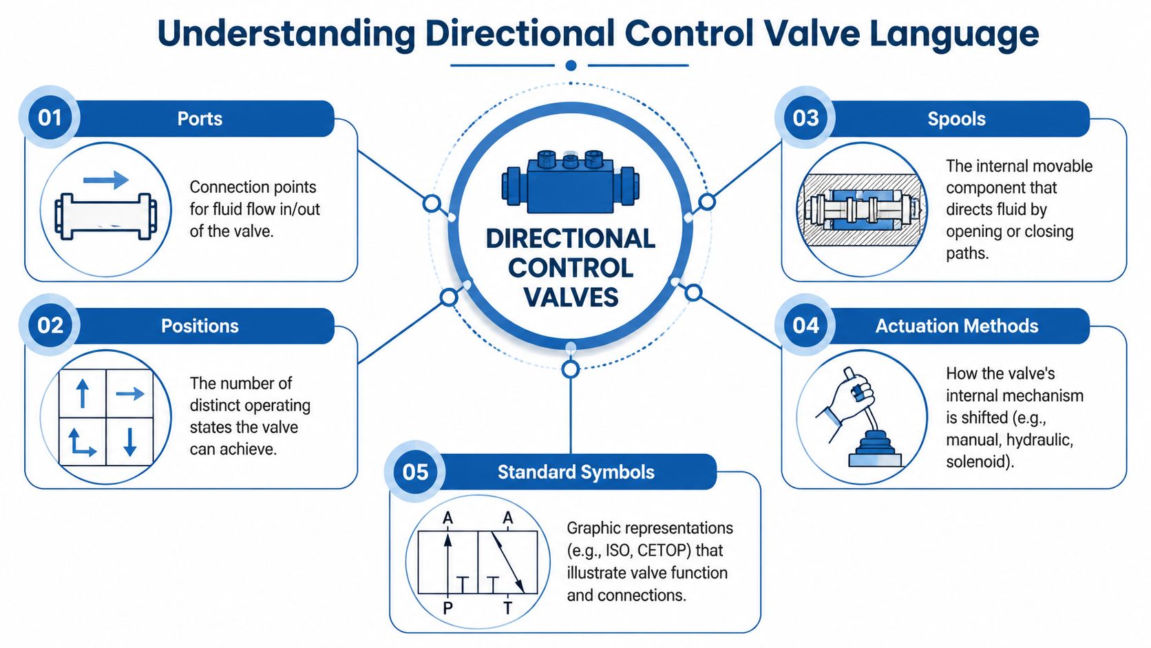
Ports mean physical connection points
Think of the valve as a railway signal box for oil. The ports are the tracks coming in and out.
The common labels are straightforward:
- P port carries pressure oil from the pump.
- T port returns oil to tank.
- A and B ports go to the actuator, usually the two sides of a double-acting cylinder or the two work lines of a motor.
If someone hands you a valve symbol and you can identify P, T, A, and B, you're already halfway there. On many jobs, confusion doesn't come from the valve being complex. It comes from people not checking which line is supposed to be pressure, tank, or work port before installation.
Positions tell you how many operating states exist
Each square in the symbol represents one spool position. A two-position valve has two states. A three-position valve has three states, usually left, centre, and right.
That centre condition matters more than many new engineers realise. It decides what the machine does when nobody is commanding movement.
A centre can be arranged to:
- Block ports so the actuator is held
- Open paths to tank so flow unloads
- Create a float condition so a cylinder can move freely under external force
The wrong centre condition causes plenty of field problems. A machine that should hold may creep. A pump that should unload may run against resistance. A function that should float may lock solid.
Ways tell you how many ports are controlled
When someone says 4/3 valve, they mean four-way, three-position. Four ports are involved. Three operating positions are available.
A 3/2 valve has three ports and two positions. A 4/2 valve has four ports and two positions. This naming convention sounds dry at first, but once you know it, valve datasheets become much easier to read.
For a useful reference when reading hydraulic diagrams, MA Hydraulics has a page on hydraulic circuit symbols that helps decode common schematic notation.
How to read the symbol without overthinking it
Use this order:
- Find the centre square first. That shows the valve's normal or spring-centred state.
- Identify P, T, A, and B. That tells you what each connection is supposed to do.
- Follow the arrows. These show allowed flow paths.
- Look for blocked ends. These show closed ports.
- Check the actuation and spring symbols. They tell you how the spool moves and how it returns.
Practical rule: If you can't explain the centre position in one sentence, don't sign off the valve selection yet.
Symbols describe function, not build quality
Two valves can share the same hydraulic symbol and behave differently in service. One may shift cleanly and tolerate harsh duty. Another may be more sensitive to contamination or internal wear. The symbol tells you what the valve is meant to do in the circuit. It doesn't tell you how well it will do it over time.
That's why symbol literacy is only the starting point. The next question is what type of valve mechanism sits behind that symbol.
Common Directional Control Valve Types
The same hydraulic function can be achieved by different internal designs, and those designs bring very different behaviour in service. From these considerations, practical selection begins.
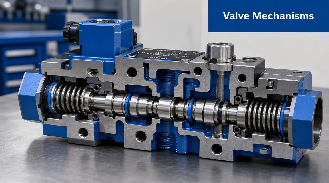
Spool valves and where they make sense
A spool valve uses a machined spool sliding inside a valve body to open and close flow paths. This is the most common arrangement in mobile and industrial hydraulics because it's versatile, compact, and available in many configurations.
Spool valves suit applications where you want:
- smooth directional switching
- compact packaging
- multiple centre options
- easy integration into sectional or CETOP assemblies
Their weakness is that they usually allow some internal leakage by design. In many circuits that's acceptable. In some holding applications, it isn't.
Poppet valves and where they earn their keep
A poppet valve seals by seating an element against a port. That makes it attractive where near-zero internal leakage matters more than smooth metering feel.
Typical reasons to choose a poppet-style arrangement include:
- Load holding where drift is unacceptable
- Positive shut-off in safety-related parts of a circuit
- Applications with leakage sensitivity during standby or neutral conditions
The trade-off is that poppet arrangements can be less forgiving when the job needs smooth transition or fine modulation through the valve itself.
The actuation method changes the real behaviour
A valve's internal type is only part of the story. You also need to know how it shifts.
Common actuation methods include:
| Actuation method | Typical use | What it does well | What to watch |
|---|---|---|---|
| Manual lever | Simple mobile functions | Direct operator control | Operator effort and packaging |
| Direct solenoid | Smaller valves and fast electrical switching | Good for straightforward automation | Limited force on larger main stages |
| Pilot-operated solenoid | Higher flow and larger valves | Shifts larger main spool with lower electrical effort | Needs sound pilot supply and cleanliness |
| Hydraulic pilot | Remote operation in mobile systems | Useful where operator linkage is impractical | Pilot circuit condition matters |
A good visual explainer helps if you want to see different arrangements in motion:
Pilot-operated valves for higher flow duties
When a main spool has to shift substantial flow at high pressure, pilot operation becomes very useful. The pilot stage does the switching work that a direct solenoid alone may struggle with on a larger valve.
The Danfoss Vickers DG5V-8 series is a clear benchmark. It's a solenoid-controlled, pilot-operated, subplate-mounted directional valve rated to 350 bar on all ports, as shown in the Danfoss DG5V-8 technical literature. That pressure class is typical of serious mobile and industrial duties.
The catch is simple. Pilot-operated valves only behave properly when the pilot oil is clean and stable.
If pilot pressure is weak or contaminated, the valve may chatter, shift slowly, or stop short of full stroke.
What works and what doesn't
What works is matching the internal mechanism to the duty. Spool valves work well for general directional control, modular stacks, and machine functions that need flexibility. Poppet styles work well when shut-off quality matters more than spool-like behaviour. Pilot operation works well when you respect pilot supply conditions.
What doesn't work is buying on headline specification alone. A valve can have the right port count and pressure rating and still be the wrong answer if the circuit needs tight load holding, poor maintenance tolerance, or frequent cold starts in dirty service.
The Power of Standardisation CETOP and Modular Valves
Standardisation saves time in design, reduces grief in maintenance, and gives buyers more flexibility when stock is tight. In hydraulic directional control valves, CETOP and ISO 4401 interfaces are the closest thing the industry has to plug-and-play mounting.
Why CETOP matters on real machines
A CETOP pattern is not a valve type. It's a standard mounting face and port layout that allows compatible valves and subplates to fit the same interface. For OEMs and repair teams, that matters because it reduces custom pipework and makes replacement more predictable.
In UK hydraulic systems, CETOP and ISO 4401 interfaces are commonly used in modular manifold assemblies because they reduce plumbing complexity and improve serviceability. Practical component benchmarks in this class reach up to 350 bar (5100 psi), as shown in this Walvoil sectional valve document used as a pressure reference.
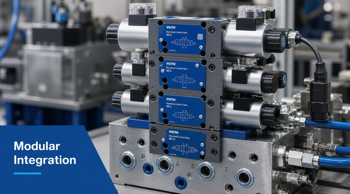
Modular stacks reduce pipework and fault-finding time
The gain isn't just neat packaging. It's system clarity.
With a modular arrangement, you can build valve functions into a stack rather than scattering them around the machine on separate lines and fittings. That usually means:
- Less external plumbing which cuts leak points
- Simpler manifold design which helps assembly and repeatability
- Cleaner servicing because functions are grouped in one place
- Easier upgrades when a pressure, flow, or check module needs to be added
For engineers working on bespoke circuits, manifold block design becomes a major part of making these assemblies practical and serviceable.
The trade-off nobody should ignore
Modularity is useful, but only if the stack still gives proper access and sensible flow paths. I've seen compact assemblies that looked excellent on paper and became awkward the moment somebody had to test a pressure point, replace a seal, or remove a single module without disturbing the rest.
A tidy manifold also won't rescue a poor valve choice. Standardisation helps with interchangeability and service access. It doesn't remove the need to check centre condition, leakage behaviour, pilot requirements, and contamination sensitivity.
Compact design is only good design if a service engineer can still work on it.
Where modular valves fit best
They're particularly effective in:
- Industrial power units where space and access need balancing
- Agricultural and mobile equipment where pipe reduction helps reliability
- Repeat-build OEM projects where standard interfaces simplify production
- Retrofit work where an old pipe-heavy layout needs rationalising
Used properly, CETOP and modular valves bring order to a hydraulic system. Used badly, they just hide complexity in a smaller space.
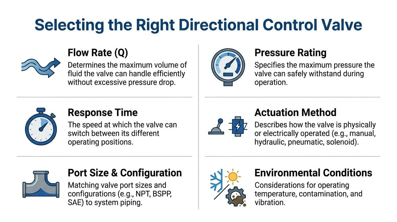
How to Select the Right Valve Performance and Sizing
A valve that looks fine in the catalogue can still give a machine slow cycle times, heat build-up, load drift, and awkward control once it is on the job. Selection affects more than function. It affects energy use, service life, and how often the maintenance team gets called back.
Start with the duty cycle and circuit behaviour
The first question is not port size. It is how the valve will be used on the machine.
A lightly used clamp circuit gives you more room for compromise than a press, a materials handling function, or a mobile machine spool that is shifted repeatedly under load. In UK industrial and mobile work, that difference shows up quickly in oil temperature, operator complaints, and wear.
Check these points before choosing anything:
- Required flow at the actuator so cylinder or motor speed is met without excessive pressure drop
- Maximum working pressure, including shock or transient conditions, so the valve has sensible margin
- Centre condition and neutral behaviour so the machine unloads, holds, or stops in a controlled way
- Actuation method so manual, solenoid, pilot, or proportional control suits the operator and the control system
- Internal leakage level so standby losses and actuator drift stay within what the application can tolerate
Sizing on nominal flow alone is a common mistake. An oversized valve can make low-flow control vague. An undersized valve creates restriction, heat, and wasted power. The right choice sits in the useful operating range, not at the edge of the chart.
Pressure loss and leakage affect running cost
Buyers often compare purchase price first. The machine pays for pressure loss and leakage for years after that.
Every directional valve introduces some restriction. If the pressure drop across the valve is higher than it needs to be, the power unit works harder and the oil runs hotter. On a high-duty industrial unit or a mobile machine with limited cooling, that shows up as reduced efficiency and shorter oil life.
Leakage needs the same level of attention. Some internal leakage is normal in spool valves, but the acceptable amount depends on the job. If the function must hold a load, maintain position, or sit in neutral for long periods, leakage is a design issue, not a footnote. A valve that is cheap to buy can become expensive once drift, heat, and nuisance faults start appearing. For a practical view of common hydraulic faults linked to poor component choice, see these hydraulic valve problems and their typical causes.
Purchase price is easy to see. Pressure loss, leakage, and heat are what the machine keeps paying for.
Control method should match the machine, not fashion
Electrical integration now matters in many applications, but that does not mean every circuit needs proportional control.
Simple on-off directional valves still suit a large amount of plant, workshop equipment, agricultural machinery, and straightforward OEM builds. They are easier to set up, generally less sensitive to wiring and tuning issues, and often cheaper to replace. Proportional or electro-hydraulic valves earn their place where smoother motion, variable speed control, automation, or PLC integration justifies the extra cost and tighter cleanliness requirements.
I would treat this as a trade-off question. Better controllability can improve productivity and reduce shock loading, but only if the rest of the system is designed to support it. A proportional valve fitted into a circuit with poor filtration, unstable voltage, or weak commissioning discipline will not behave like the brochure suggests.
Directional Valve Type Selection Guide
| Valve Type | Primary Use | Leakage | Contamination Tolerance | Cost |
|---|---|---|---|---|
| Spool valve | General directional control in mobile and industrial circuits | Usually some internal leakage | Moderate, depends on design and clearances | Often moderate |
| Poppet valve | Load holding and positive shut-off duties | Very low internal leakage | Often better than fine-clearance spool designs | Often moderate to higher |
| Direct-acting solenoid valve | Smaller circuits and straightforward automation | Depends on internal sealing arrangement | Moderate | Often lower to moderate |
| Pilot-operated valve | Higher flow and larger main stage control | Depends on valve design and pilot health | Sensitive to poor pilot cleanliness | Often higher than simple direct-acting types |
| Proportional directional valve | Variable control and smoother machine response | Application dependent | Typically needs better cleanliness and electrical setup | Often higher |
A practical buying approach
For replacements and new builds, match the valve to the whole circuit rather than treating it as a threaded spare part. MA Hydraulics Ltd supplies directional, proportional, modular, and inline hydraulic valve options as part of its wider hydraulic component range, which is useful when the job involves fitting the valve to a broader system rather than replacing like for like.
The sensible approach is usually the one that lasts. Size for real flow, not optimistic catalogue assumptions. Check pressure drop at your expected operating point. Choose a centre condition that gives the machine the neutral behaviour it actually needs. Be realistic about oil cleanliness and pilot quality. If the load must stay put, make sure the valve arrangement can hold it properly instead of assuming the directional valve will do that on its own.
Installation Maintenance and Troubleshooting Tips
A directional valve often gets blamed after a machine starts drifting, hesitating, or refusing to shift on a cold Monday morning. In practice, the valve is only one part of the fault path. Installation quality, oil condition, pilot supply, return line backpressure, and electrical health usually decide whether the valve gives years of reliable service or becomes a repeat callout.
That matters in UK industry and mobile plant because downtime costs more than the valve. A poor install or lazy maintenance routine shows up later as wasted power, nuisance faults, inconsistent motion, and parts swapping that never quite fixes the problem.
Installation details that prevent trouble
Good installation starts before the valve is bolted down. Check the manifold or subplate face for burrs, paint, corrosion, and pulled threads. A small defect on the mounting face can create an internal leak path, distort the valve body, or cut a seal during assembly.
Use a disciplined install routine:
- Inspect the mounting face for burrs, nicks, and trapped debris.
- Check seals and O-rings before fitting. A twisted or nicked seal can look like a much larger hydraulic fault.
- Torque fixings correctly and evenly. Uneven clamping can affect sealing and spool movement.
- Confirm port identification before startup. Misconnected P, T, A, or B lines still catch people out.
- Flush or clean the circuit properly if the system has been rebuilt, repaired, or modified.
On pilot-operated valves, give the pilot line and drain line the same attention as the main ports. I have seen perfectly good valves replaced because a restricted drain line stopped the stage from shifting properly. The replacement behaved exactly the same.
Maintenance that actually extends valve life
Oil cleanliness has a direct effect on valve life, response, and leakage. Spools tolerate dirt badly. Pilot stages usually tolerate it even less. If a machine uses electro-hydraulic or proportional control, weak maintenance practice tends to show up faster because those valves respond to small hydraulic and electrical faults instead of masking them.
The maintenance routine does not need to be complicated. It needs to be consistent.
Check filter condition. Watch for varnish, water contamination, and debris after hose failures or pump damage. Inspect coil plugs, DIN connectors, cable glands, and earths on outdoor or washdown equipment. On mobile applications, pay attention to vibration damage and water ingress around connectors and coils.
For a broader look at recurring faults, MA Hydraulics has a useful page on common hydraulic valve problems and their likely causes.
Symptom checks that save time
| Symptom | Likely cause | Practical check |
|---|---|---|
| Valve fails to shift | Coil fault, wiring issue, jammed spool, inadequate pilot pressure | Verify the electrical command first, then check pilot supply and spool freedom |
| Sluggish actuator movement | Contamination, pressure drop, partial spool movement, return restriction | Check filtration condition, supply pressure, and tank line backpressure |
| Actuator creeps in neutral | Internal leakage, unsuitable centre condition, worn internals, cylinder leakage | Isolate the actuator and valve separately before deciding where the leakage sits |
| Chatter or unstable shifting | Dirty pilot oil, unstable pilot pressure, sticking internals | Inspect pilot source stability, contamination level, and spool condition |
| External leakage | Damaged seals, poor mounting face, loose fittings | Inspect sealing surfaces and recheck assembly torque |
Start with the checks that prove or eliminate the simple faults quickly. Confirm the command signal. Confirm that the coil is energising. Confirm pilot pressure, if fitted. Then move on to pressure readings, spool movement, and leakage tests.
Fault-finding habits that prevent wasted spend
Methodical troubleshooting saves money. Procurement teams feel the cost when parts get changed on suspicion. Maintenance teams lose hours when the actual fault sits elsewhere in the circuit.
Check the whole circuit before ordering a replacement valve. A blocked return filter, collapsed hose liner, low pilot pressure, incorrect voltage at the coil, or poor earthing can all make a healthy valve look defective. The reverse is also true. Internal bypassing or incomplete spool shift inside the valve can look like weak pump performance until pressure and flow are tested properly.
The best service engineers work through the schematic, confirm the expected valve state, and test in sequence. That approach gives a more reliable machine and lower running cost than swapping components until the symptom disappears.
Your Next Step to a Reliable Hydraulic System
Directional control valves look straightforward until you have to select one for a machine that has to work every day, hold load properly, respond cleanly, and still be serviceable years later. That's when the details start to matter.
The core points are simple. The valve determines where oil goes and what the machine does in neutral. The symbol tells you the intended function, but not whether the hardware suits the duty. Spool, poppet, direct-acting, pilot-operated, modular, CETOP, proportional. Each has a place. None is right for every circuit.
The biggest mistake is treating valve selection as a basic catalogue exercise. In real UK industrial and mobile applications, the right choice depends on leakage, pressure loss, contamination tolerance, pilot reliability, electrical integration, and maintainability. Those aren't small details. They decide whether the machine feels right and whether it stays reliable.
Procurement teams usually want a clear replacement path and a sensible price. Engineers want the machine to behave properly. Maintenance teams want something they can diagnose and service without dismantling half the installation. Good valve selection sits at the point where those three needs meet.
If you're reviewing a current valve, specifying a new circuit, or trying to solve drift, sluggish movement, or poor control feel, it helps to speak to someone who can read the problem as a system issue rather than just a part number issue. That's especially true when the valve choice affects manifolds, pilot circuits, power pack layout, or the way the machine interfaces with electrical controls.
A reliable hydraulic system rarely comes from picking the most complex valve. It comes from choosing the one that matches the machine, the environment, and the way people will maintain it.
For application advice, replacement valves, or help matching the right directional control valve to your system, contact MA Hydraulics Ltd. Phone 01724 279508 today, or send us a message.
