
A reduction gearbox is a mechanical device that trades speed for torque. If a 10-tooth driving gear turns a 50-tooth driven gear, you get a 5:1 reduction, so the output turns once for every five input rotations and torque rises by the same factor in an ideal system.
That's the practical answer, but it usually comes up because something on a machine isn't matching up properly. The motor is happy at its own speed, but the conveyor, auger, winch, hydraulic pump or PTO-driven attachment needs something slower and stronger. Connect them directly and you often end up with the wrong shaft speed, poor starting performance, overheating, or a drive that won't survive real duty.
For UK OEMs and MRO teams, that gap between motor speed and usable machine speed is where a gearbox earns its keep. It lets the prime mover operate in a sensible range while the driven equipment gets the torque it needs. That sounds simple on paper. In practice, selection is where people get caught out. Ratio is only the start. Duty cycle, mounting, shock loading, lubrication, frame compatibility, and whether the machine really needs fixed reduction or variable speed all matter just as much.
A lot of engineers working across mixed mechanical and hydraulic systems also have to think beyond the gearbox itself. If you're assessing packaging, tolerances, driveline interfaces, and how mechanical assemblies behave as part of a larger machine, the Sheridan Technologies complex hardware guide is a useful reference because it looks at the wider integration problem rather than treating components in isolation.
Your Introduction to Reduction Gearboxes
The easiest way to understand what is a reduction gearbox is to look at the job it solves on a real machine. A motor or engine can produce useful power at relatively high speed, but many driven loads don't want high speed. They want controlled rotation and enough twisting force to move weight, overcome startup resistance, or keep turning when the load varies.
That's why reduction gearboxes are common in agriculture, materials handling, plant equipment, compact power packs, and factory automation. They sit between the power source and the driven component and convert that high-speed input into a lower-speed output with more usable torque. In hydraulic systems, that often means matching a motor or PTO input to equipment that must turn slower without giving away pulling power.
What the gearbox means for the machine
A gearbox changes the behaviour of the whole drive line, not just the shaft speed. When it's matched properly, the motor operates in a healthier range, startup is more controlled, and downstream parts see a more appropriate load. When it's matched badly, problems spread quickly. Bearings run hotter, couplings complain, seals suffer, and operators start describing the machine as “sluggish”, “snatchy”, or “always noisy under load”.
In workshop terms, the gearbox isn't there to make the spec sheet look tidy. It's there to make the machine usable.
A good reducer makes an ordinary motor useful on a demanding load. A bad one turns a workable machine into a maintenance problem.
Where people usually go wrong
Newer engineers often focus first on nominal speed. Procurement teams often focus first on footprint or price. Neither is enough on its own.
A reduction gearbox must suit actual machine conditions:
- Starting behaviour matters because some loads are easy once moving but hard to break away.
- Load variation matters because not every conveyor, mixer, or PTO implement runs at one steady point.
- Mechanical fit matters because replacing a failed unit is often about shaft, flange, and mounting compatibility before anything else.
- Service life matters because the wrong ratio or wrong housing style can shorten the life of the entire drive train.
Core Principles Trading Speed for Torque
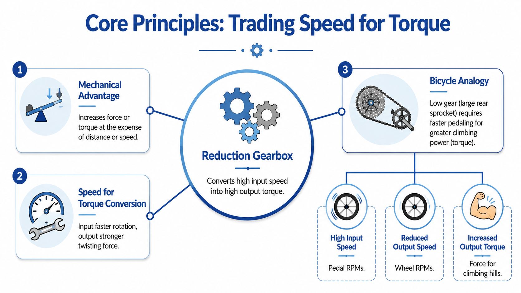
At the heart of a reduction gearbox is mechanical advantage. You give up rotational speed to gain torque. That's the same principle you feel on a bicycle when you shift into a lower gear for a hill. Your legs spin faster, but the bike can push harder against resistance.
In a gearbox, the ratio comes from the relationship between the driving gear and the driven gear. A practical example is straightforward: a 10-tooth driving pinion turning a 50-tooth driven gear gives a 5:1 reduction, so the output shaft turns once for every five input rotations and torque rises by the same factor in an ideal system, as explained in STOBER's gear reduction calculation guide.
How to read the ratio properly
The ratio tells you two things at once:
- Output speed falls in proportion to the reduction ratio
- Output torque rises in proportion to the reduction ratio, before real losses are considered
That second part is the reason gear reducers are so useful. They let a smaller motor or engine do work that would otherwise need a much larger direct-drive arrangement. For machine builders, that can simplify the package. For maintenance teams, it can make a drivetrain more durable if the ratio is sensible for the duty.
Why this matters in hydraulic and mobile equipment
The principle becomes more useful when you stop treating it as classroom maths. On real equipment, the gearbox is part of a larger power chain that might include an electric motor, a diesel engine, a PTO shaft, a hydraulic motor, a coupling, and a driven load with uneven resistance.
If you're pairing drive components where low-speed torque matters, it helps to look at options built for that job, such as high torque hydraulic motors, because the reducer and the prime mover have to be considered together rather than as separate purchases.
Practical rule: If the machine needs force more than shaft speed, direct drive usually isn't the right answer.
What the theory doesn't tell you on its own
Textbook explanations make reduction sound lossless and tidy. Real installations aren't. You have friction, backlash, heat, lubrication effects, alignment issues, and changing loads. The ratio still defines the basic behaviour, but the machine only performs well when the whole drive line is designed around that behaviour.
That's why engineers who understand ratios but ignore mounting stiffness, duty pattern, or shock loading still end up with underperforming systems. The gearbox gives you the mechanical advantage. Integration determines whether you keep it.
A Practical Guide to Gearbox Types
A reducer that works well on a bench can still be the wrong choice once it is bolted into a UK machine with a tight chassis, a PTO speed to match, and a duty cycle that swings from light running to shock loads. Gear type affects service life, noise, efficiency, mounting layout, and how forgiving the unit will be when the rest of the driveline is less than perfect. For OEM design teams and MRO engineers, that matters more than the catalogue description.
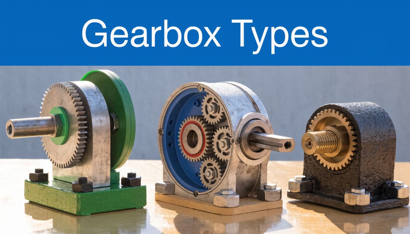
A simple gear pair still gives the baseline. A 20-tooth input gear driving a 60-tooth output gear gives a 3:1 reduction. On paper, that is straightforward. In practice, the useful question is whether that gear form, shaft arrangement, and efficiency level suit the machine you are building or repairing.
Spur gearboxes
Spur gearboxes are the plain-speaking option. Straight teeth, simple manufacture, and usually the easiest internals for a maintenance team to inspect and replace.
They suit lower-speed duties where purchase cost, ease of servicing, and parts availability matter more than refinement. I would still be cautious using spur units in applications where the prime mover runs fast or the machine sits close to operators for long shifts, because gear noise rises quickly and impact loading is less forgiving than with smoother tooth engagement.
For some PTO-driven equipment, that simplicity is a real advantage. For enclosed industrial skids with stricter noise expectations, it often is not.
Helical gearboxes
Helical gears use angled teeth, which brings the load in more gradually across the mesh. That usually means smoother running, better noise behaviour, and a gearbox that copes well with continuous duty.
The trade-off is axial load. Bearings, housing stiffness, and shaft support need to be right or the benefits are lost. That is one reason helical units tend to be a solid choice for OEMs chasing decent efficiency and acceptable sound levels, but not always the cheapest answer for a straightforward replacement job in the field.
If a machine runs for hours rather than minutes, helical is often where the shortlist starts.
Worm gearboxes
Worm gearboxes earn their place because they solve packaging problems. They give high reduction in a compact right-angle layout, which can make life much easier on mixers, conveyors, feeders, and compact auxiliary drives.
They also come with a real penalty. Efficiency is lower than spur, helical, or planetary arrangements, especially as ratios rise, and that lost power turns into heat. In intermittent service, that may be acceptable. In continuous duty, or where a hydraulic motor already runs hot and margins are tight, it can be the wrong choice even if the mounting layout looks ideal.
Worm units can still be the practical answer. They just need honest assessment of thermal limits, not just ratio and price.
For a visual refresher on how common gearbox formats differ mechanically, this short video is worth a look.
Planetary gearboxes
Planetary gearboxes are used where torque density and compact packaging matter. Multiple planet gears share the load, so you can get high torque capacity from a relatively small housing.
That makes them useful in mobile equipment, wheel drives, winches, and dense powerpacks where space is expensive. The downside is cost, internal complexity, and sometimes a less friendly repair path for MRO teams who would rather swap standard bearings and gears than replace a more integrated assembly. They are excellent when the machine needs that performance. They are unnecessary when a simpler parallel-shaft unit will do the same job with easier service access.
Gearbox type performance comparison
| Gearbox Type | Key Advantage | Typical Efficiency | Noise Level | Cost |
|---|---|---|---|---|
| Spur | Simple construction and straightforward servicing | Often good in simple, well-aligned drives | Higher at speed | Lower to moderate |
| Helical | Smoother running and good load handling | Usually better than worm in continuous duty | Lower than spur | Moderate |
| Worm | High reduction in compact right-angle layouts | Lower, especially at higher ratios | Generally moderate | Moderate |
| Planetary | High torque density in compact space | Often high, depending on stage count and design | Typically well controlled | Moderate to higher |
What usually works in practice
Selection usually comes down to what the machine can tolerate.
- Choose spur when low cost, simple servicing, and straightforward replacement matter more than noise.
- Choose helical when the unit will see long running hours and you need smoother operation with good all-round efficiency.
- Choose worm when the layout demands a right-angle drive and you can accept the heat and efficiency penalty.
- Choose planetary when space is tight, torque demand is high, and the budget supports a more compact, more specialised unit.
For UK OEMs and maintenance teams, the best gearbox type is the one that matches the actual duty cycle, fits the mounting envelope, and does not create a new problem for the hydraulic motor, PTO shaft, or operator standing next to it.
Understanding Multi-Stage Reduction and Efficiency
A common failure point in real machine design is asking one gear stage to do too much. On paper, a very large ratio in a single step can look tidy. In the housing, it often means larger gears, awkward centre distances, higher tooth loads, and a package that no longer suits the machine.
Multi-stage reduction solves that packaging problem by splitting the ratio across two or more meshes. Two moderate stages can deliver a large overall reduction while keeping the gears, shafts, and bearings within a more workable size range. For OEM teams trying to fit a reducer between a prime mover and a hydraulic drive, that usually matters more than the textbook ratio itself.
Single reduction versus double reduction
A single reduction gearbox has one gear mesh between input and output. A double reduction gearbox adds a second stage, which allows a lower output speed and higher torque multiplication from a compact unit. Motion Control Tips gives a useful overview of how gear reducers trade speed for torque and why multiple stages are used for higher ratios.
The trade-off is straightforward. Every added mesh creates another source of friction, heat, and noise. In practice, that means a double or triple reduction unit can be the right answer for a slow, heavily loaded machine, but it also places more demands on lubrication quality and thermal control.
I usually treat stage count as a system decision, not just a gearbox decision.
If the reducer is driven by a hydraulic motor or a PTO-driven hydraulic pack, the losses in the gearbox do not stay inside the gearbox. They show up as heat the wider system must carry. On compact mobile equipment using a PTO hydraulic pump arrangement, that can affect oil temperature, prime mover load, and the margin available on continuous duty.
Efficiency is a real selection factor, not a catalogue footnote
No gearbox transfers all input power to the output shaft. An extra stage gives ratio flexibility, but it also reduces overall efficiency because each mesh, bearing set, and seal adds loss. Engineers at SEW-EURODRIVE explain in their gear unit efficiency guidance that efficiency depends on gear geometry, lubrication regime, speed, and load point, not just gearbox type.
That matters in two places.
First, available output torque under continuous duty may be lower than a quick ratio calculation suggests once mechanical losses are included. Second, wasted power becomes heat, and heat shortens oil life and bearing life if the housing cannot reject it fast enough. UK MRO teams see this regularly on replacement jobs where the ratio is correct, but the new unit runs hotter because the actual duty cycle includes long loaded periods, frequent starts, or poor airflow around the casing.
What this changes on a real machine
For practical selection, the question is not whether more stages are good or bad. The question is whether the machine benefits enough from the extra reduction to justify the efficiency penalty and added complexity.
Check these points before specifying a multi-stage unit:
- Required output speed under real input speed, not nominal motor speed only
- Actual torque demand across the duty cycle, including starting load and shock events
- Thermal capacity of the gearbox and surrounding installation
- Lubrication method and oil grade, especially on long-running or high-load duty
- Space saved by a staged design versus the maintenance access you lose
For conveyors, mixers, agricultural machinery, and PTO-driven hydraulic systems, multi-stage reduction is often the practical way to get the speed down without an oversized drive layout. For lighter-duty equipment with shorter run times, one stage can be easier to maintain and more forgiving in service.
Additional ratio is useful. It is never free.
Sizing and Selection for UK Hydraulic and PTO Systems
Ratio alone doesn't size a gearbox properly. It tells you the speed relationship, but it doesn't tell you whether the unit will survive the actual machine. That's where many replacements go wrong, especially when a failed reducer is swapped on nominal output speed alone.
The more useful question is this: what does the load look like over time? That's the key issue highlighted in STOBER's discussion of gearbox versus reducer terminology and sizing. The practical UK procurement problem isn't defining the gearbox. It's choosing ratio, service factor, and mounting when the motor isn't running at one fixed duty point.
Start with duty, not catalogue speed
A gearbox on a smooth conveyor has a different life from a gearbox on a baler, mixer, or materials handling system that sees frequent starts, stops, and load swings. If the machine starts under load, reverses often, or sees shock, the reducer must be chosen for that reality.
For UK MRO teams replacing units in agriculture or materials handling, the same source makes an important point: the primary concern is often compatibility and life expectancy, not the textbook definition of the component.
The questions that matter on a live job
Before selecting a unit, check these points in order:
- Duty cycle. Is the load steady, intermittent, or abusive?
- Starting condition. Does the machine start unloaded, or does it have to break away under resistance?
- Mounting arrangement. Foot mount, flange mount, shaft mount, or something adapted in the field?
- Input and output interfaces. Motor shaft, coupling, PTO layout, keyway, spline, hollow shaft, or legacy pattern?
- Environment. Indoor, washdown, mobile, dusty, damp, or exposed to shock and vibration?
If the drive ties into tractor or mobile plant architecture, it also helps to check the hydraulic side of the system at the same time. A PTO hydraulic pump arrangement often dictates input speed, rotation, and mounting choices that affect gearbox selection just as much as the driven load does.
UK-specific fit is often the deciding factor
In theory, many reducers can produce the same ratio. In practice, only a smaller group will fit the motor frame, shaft arrangement, guarding, and machine envelope without creating extra fabrication work.
That's particularly true when replacing older equipment. Common UK setups may be built around IEC motor frames, established PTO layouts, or legacy machine clearances. If a replacement needs custom plates, offset couplings, or shaft modifications, the cheapest gearbox on paper often becomes the most expensive choice by the time the machine is back in service.
One sensible way to buy
Procurement works better when engineering supplies the following with the enquiry:
| Selection item | Why it matters |
|---|---|
| Required output speed | Establishes the reduction target |
| Expected running load | Prevents under-sizing |
| Start and stop pattern | Influences service factor choice |
| Mounting style | Avoids installation rework |
| Shaft and flange details | Protects compatibility |
| Environment and lubrication constraints | Supports service life |
Where reduction gearboxes are being sourced alongside hydraulic components, MA Hydraulics Ltd is one UK option for matching gearbox, PTO, and related drive components within the same application discussion rather than treating each part separately.
Installation Lubrication and Failure Prevention
A well-sized gearbox can still fail early if it's installed badly or maintained casually. Most premature problems aren't mysterious. They usually start with misalignment, poor mounting, contaminated oil, wrong oil level, or a machine running in conditions the gearbox wasn't prepared for.
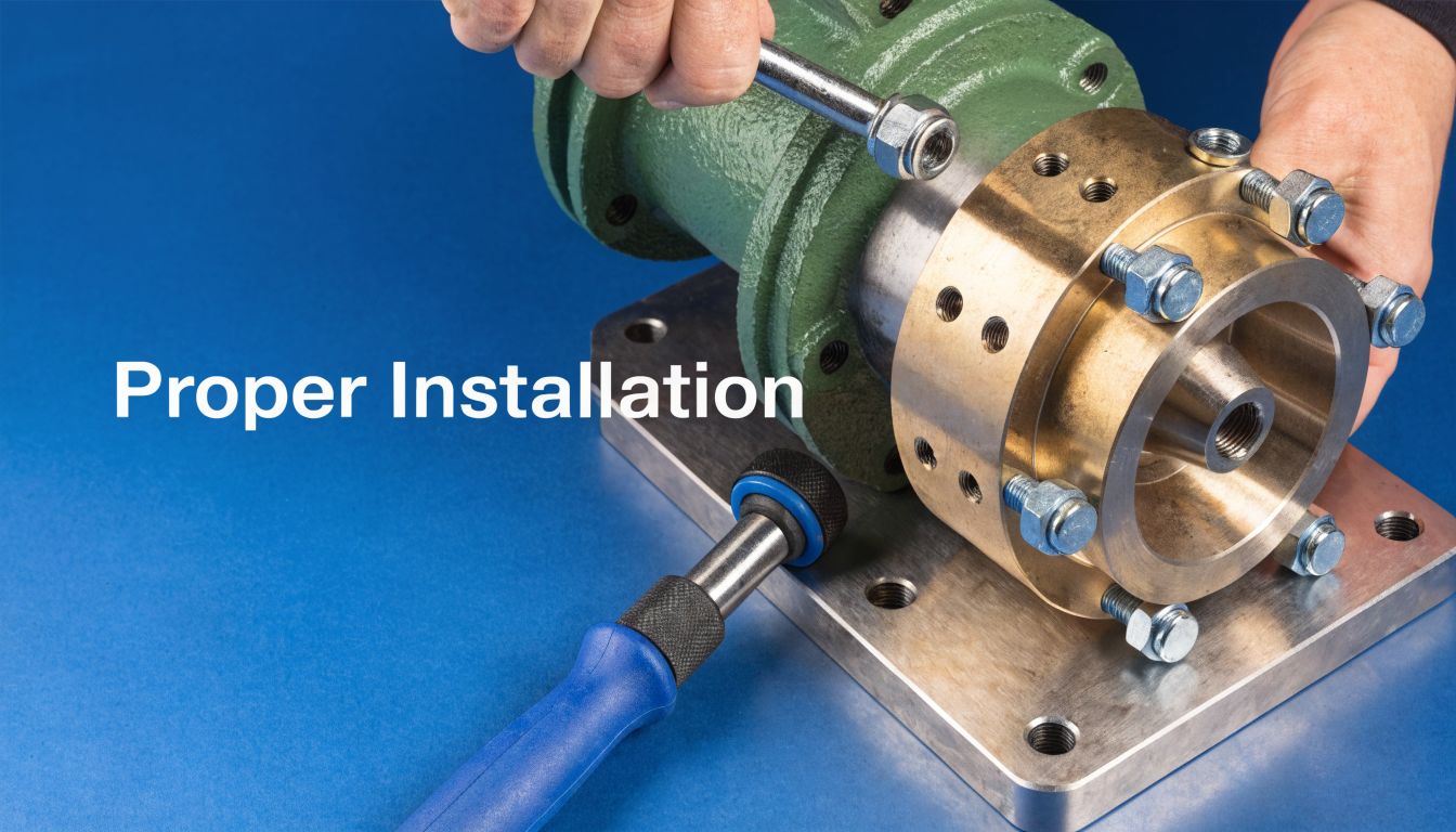
Installation points that matter
The housing needs to sit on a rigid, flat mounting surface. If the base twists during tightening, the internals pay for it later through bearing stress and shaft misalignment. Couplings should also be fitted without forcing components together. If someone needs to “persuade” the assembly into place, alignment likely isn't right.
Pay attention to the approved mounting orientation. Lubrication behaviour changes with orientation, and a unit that works perfectly in one position can run short of proper oil distribution in another.
If a gearbox runs hot immediately after installation, don't assume it simply needs to bed in. Check alignment, fill level, and mounting attitude first.
Lubrication is not a minor detail
Oil choice affects heat, wear, and gear tooth protection. So does oil level. Too little oil starves components. Too much can increase churning and temperature. If the application calls for a specific lubricant type or viscosity, that isn't optional paperwork. It's part of the gearbox design.
Routine inspection should include:
- Oil condition. Darkened or burnt-smelling oil points to overheating.
- Contamination check. Milky oil usually means water ingress.
- Leak inspection. Seals don't just fail on their own. Pressure, wear, shaft condition, and overheating all contribute.
- Noise trend. A change in sound under the same load often appears before visible damage.
- Surface debris. Fine metallic content in drained oil is an early warning, not workshop decoration.
For teams building a maintenance routine around predictable service intervals, preventive maintenance plans are a practical way to catch these signs before they become an unplanned stoppage.
Common failure signs in service
Gear tooth damage often starts as pitting and develops into more serious surface breakdown if load, lubrication, or alignment problems remain. Bearings usually announce trouble through noise, heat, and looseness before complete failure.
If you work across driveline systems more broadly, the warning patterns seen in gearboxes have a lot in common with other rotating powertrain faults. This piece on diagnosing transmission issues for repair shops is useful because it focuses on practical fault symptoms technicians encounter in the field.
A simple prevention habit
Don't only inspect the gearbox when it has already become loud. Check it when the machine still appears healthy.
Use a repeatable routine:
- Listen for change at constant load.
- Check temperature behaviour against normal operation.
- Inspect oil before the next interval is overdue.
- Look at seals, shafts, and mounting bolts for movement or leakage.
- Record findings so small changes don't get dismissed as “probably nothing”.
That discipline extends service life more reliably than waiting for a visible failure.
Is a Gearbox Always the Best Choice? A Final Verdict
Not always. A reduction gearbox is excellent when the machine needs a fixed relationship between input speed and output torque, but it isn't automatically the right answer for every modern drive problem.
The comparison that matters most today is often gearbox versus variable-speed drive. As noted in Torque Transmissions' discussion of reduction gearboxes and modern drive choices, existing guidance often skips this question even though it matters in UK applications such as conveyors, mixers, and mobile plant that are being redesigned around tighter energy targets.
When a reduction gearbox is the better choice
A gearbox is often the stronger option when the application values:
- Durability under harsh mechanical conditions
- Shock load tolerance where startup or process variation is rough
- High torque density in a compact mechanical package
- Simple fixed-speed operation without needing electronic speed variation
That makes reducers well suited to plenty of real industrial and mobile work. If the machine mostly does one job at one useful output speed, a fixed-ratio mechanical solution is often easier to maintain and easier to trust.
When a variable-speed drive makes more sense
A VSD becomes attractive when the process needs speed flexibility more than pure mechanical multiplication. If operators need to change speed regularly, fine-tune process rate, or adapt output dynamically, electronic control may fit better than a purely fixed reduction arrangement.
That doesn't make the gearbox obsolete. It just means the decision should start with process behaviour, not habit.
Choose the architecture that matches the job. Don't fit a gearbox because it's familiar, and don't fit a VSD because it sounds modern.
The practical verdict
If your machine needs consistent low speed with strong torque, a reduction gearbox is usually the right starting point. If it needs frequent speed adjustment, a variable-speed solution may be the better fit. In many systems, the best result comes from combining sensible mechanical reduction with proper drive control rather than treating the two options as rivals.
For OEMs, maintenance teams, and hydraulic engineers, the main lesson is simple. Don't stop at asking what a reduction gearbox is. Ask whether the ratio, type, mounting, lubrication, and control philosophy suit the machine you have.
If you need help selecting or replacing a reduction gearbox for a hydraulic, PTO, industrial or mobile application, contact MA Hydraulics Ltd. Phone 01724 279508 today, or send us a message.
