
If you're looking at a hydraulic power unit, mobile machine, or OEM assembly and seeing hoses crossing over each other, fittings tucked into awkward corners, and valves mounted wherever there was room, the problem usually isn't just appearance. That layout tends to create pressure loss, leak risk, slower assembly, and harder fault-finding.
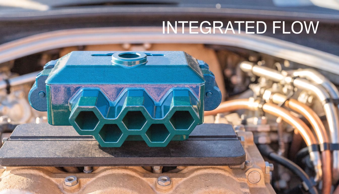
A well-executed manifold block design fixes that by pulling the circuit into one compact, machined component. Instead of treating pipework as the default, it treats flow path, service access, and manufacturability as design inputs from the start. In practice, that changes how reliable the machine is, how easy it is to maintain, and how much space you recover around the hydraulic package.
Moving Beyond Pipes to Integrated Hydraulic Manifolds
Traditional piped systems often grow piece by piece. A valve gets added later. A relief valve moves to make room for a bracket. A tee fitting appears because it is quicker than redesigning the assembly. The result works, but rarely well.
A manifold block takes the opposite approach. The circuit is consolidated into a drilled and machined block that carries the oil internally between functions. That usually means fewer joints, fewer hose runs, and a cleaner assembly.
Hydraulic manifold blocks typically reduce a system's physical footprint by 60-80% compared to conventional piped valve arrangements, while also minimising potential leak points and simplifying assembly, as noted in this overview of hydraulic manifold block history and design.
What improves in real service
In industrial machinery, the first gain is usually access. Technicians can see the valve group, test points, and ports in one place instead of tracing hoses around guards and framework. In mobile equipment, the compact layout is often even more valuable because packaging space is always tight.
There is also a reliability benefit that doesn't show up on a drawing. Every fitting you remove is one less potential leak path. Every unnecessary bend you avoid is one less place for pressure loss and heat generation.
Practical rule: If a piped circuit only exists because "that's how we always build them", it is usually worth reviewing as a manifold candidate.
A good manifold doesn't just save room. It makes the hydraulic system easier to understand. If you need a refresher on core circuit principles before laying out a block, this guide on how hydraulics work is a useful starting point.
Where designers still go wrong
The common mistake is assuming a manifold is merely a neater mounting block for existing valves. It isn't. The block changes the circuit geometry, the drilling strategy, the pressure losses, the machining sequence, and the service method.
That is why manifold block design has to be treated as an engineering task, not a packaging exercise. The best results come when the hydraulic function, the physical block, and the workshop process are developed together.
Functional Specification and Circuit Layout
Most manifold problems begin before any metal is cut. They start when the schematic is vague, the valve choice is made too early, or the layout is driven by external appearance rather than internal oil path.
The first job is to define exactly what the block has to do. That means pressure, flow, sequence, load holding, emergency behaviour, test access, and the physical constraints around the machine. If any of those are unclear, the CAD model will only hide the uncertainty for a while.
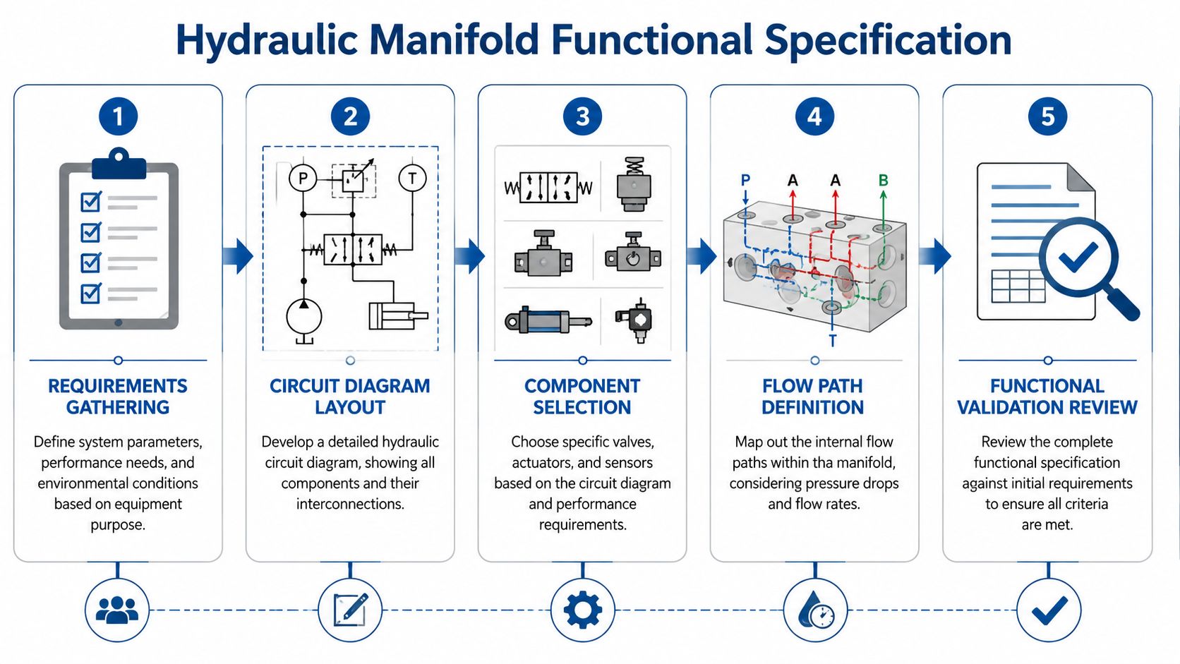
Start with the schematic, not the block
Read the hydraulic circuit as a list of functions, not just symbols. Which branch carries the highest flow. Which valve must be closest to the actuator port. Which line absolutely cannot tolerate a sharp pressure drop. Which pilot line needs isolation from a noisy main flow passage.
A useful way to work is to group the circuit into layers:
- Primary power path. Pump flow, pressure line, tank return, and main protection.
- Control functions. Directional control, pressure control, and flow control.
- Secondary support features. Gauge ports, test points, drain lines, and signal ports.
That order matters because the highest-flow passages tend to decide the block architecture. Pilot and sensing features are fitted around that, not the other way round.
If you're checking symbols or standard notation while building the function list, keep a reliable hydraulic circuit symbol reference to hand. It saves avoidable interpretation errors when multiple people review the same drawing.
Lay out valves by flow logic
Once the function is fixed, place the valves on the block faces in a way that shortens the internal routes. Do not start by making the front face look tidy. Start by reducing crossing drillings and avoiding awkward internal intersections.
A key design goal is to limit the number of turns in any single circuit path to fewer than five, which helps keep pressure drop below 2% and is critical for system efficiency, according to the Vickers manifold design guidelines.
That simple rule forces better decisions. If a valve placement creates a sixth bend, move the valve. If one branch has to weave around cavities and plugs, revisit the whole face arrangement. A manifold can look compact from the outside and still be poor internally.
Fewer turns usually beat clever drilling. The shortest clean route is normally the one that works best in service.
Questions that should be answered before modelling
A practical specification review should settle points like these:
-
What is fixed by the machine
Port orientation, mounting envelope, service access, hose exit direction, and allowable block weight often come from the machine layout and can't be negotiated later. -
What is fixed by the hydraulic duty
Relief settings, actuator speed requirements, load-holding functions, and any need for soft shifting or proportional control drive valve choice and passage size. -
What is fixed by maintenance reality
Test points need to be reachable. Cartridge valves need removal clearance. Solenoids shouldn't sit where a technician cannot unplug them without dismantling guards.
Common layout errors
Some faults appear again and again in first-pass manifold concepts:
- Overcrowded valve faces. This makes machining awkward, increases plug density, and leaves no room for tools during maintenance.
- Pilot lines routed through main-flow territory. The block becomes harder to drill cleanly and more sensitive to contamination.
- Ignoring plug strategy. Every cross drilling needs a closure method. If the plug plan looks chaotic, the internal design usually is too.
- No thought for assembly orientation. A block that can only be mounted or tested in one inconvenient position will cost time every time it is built.
The strongest layouts are usually boring on paper. Straightforward, direct, and easy to manufacture. That is exactly what you want.
Material Selection and Physical Block Design
Material choice is where many designs become either reliable or troublesome. Designers often focus on weight first, procurement focuses on price first, and production focuses on machinability first. All three matter, but pressure duty, environment, and block geometry should decide the shortlist.
For mobile machinery, aluminium is attractive because it is lighter and generally easier to machine. For heavier industrial duty, ductile iron and steel are often the safer route, especially when pressure and shock loading start to climb. If the block is going on equipment that lives outdoors in the UK, corrosion exposure also needs to be treated as a real design input, not a finishing note.
Match material to pressure and application
For systems operating above 220 bar, standard practice dictates using materials like ASTM A536 ductile iron or steel instead of aluminium to ensure long-term safety and durability under high stress. That benchmark comes from the design guidance already referenced earlier.
That doesn't mean aluminium is a poor choice. It means aluminium needs to be selected for the right duty. A compact mobile power pack with sensible loading and good protection from impact is a different proposition from a hard-worked industrial manifold subjected to repeated pressure cycling, vibration, and occasional abuse in service.
A practical material comparison looks like this:
| Material | Typical Max Pressure (bar) | Key Advantages | Common Applications |
|---|---|---|---|
| Aluminium | Up to 220 | Lower weight, easier machining, good for compact assemblies | Mobile equipment, lighter-duty manifold assemblies |
| Ductile iron | Above 220 | Better strength under sustained pressure, good durability | Industrial hydraulic power units, demanding mobile systems |
| Steel | Above 220 | High strength, suitable for severe duty and harsh service | High-pressure industrial circuits, heavy plant |
Sizing the block properly
A manifold shouldn't be made as small as possible. It should be made large enough to keep sensible wall thicknesses, allow realistic drillings, and provide access for plugs and fittings.
One dependable starting point from established manifold practice is to set the initial valve block thickness at five times the maximum valve port diameter. It is a rule of thumb, not a final answer, but it prevents the common mistake of starting with an unrealistically thin block and then forcing bad internal geometry into it.
Workshop view: If the only way to make the passages fit is to shave wall thickness everywhere, the block is undersized.
Real trade-offs in UK conditions
The UK climate matters more than many catalogue designs admit. Mobile machinery sees rain, road dirt, fertiliser exposure, washdown, and long periods standing outside. Industrial environments add coolant mist, humidity, and corrosive contaminants depending on the sector.
That changes the material conversation:
- Aluminium suits many mobile applications where weight matters, but surface protection and thread durability need thought.
- Ductile iron offers a more forgiving route for higher-pressure industrial systems and for installations where impact resistance matters.
- Steel is often chosen when the block will live in a severe environment or where pressure margin is a priority.
The cheapest billet is rarely the cheapest finished solution if corrosion, thread wear, or machining complexity causes problems later.
Design features that prevent expensive mistakes
Several physical design choices have an outsized effect on reliability:
- Port spacing needs to allow fittings and tooling clearance, not just fit on a drawing.
- Plug access should be planned so the workshop can machine, clean, and inspect the block without improvisation.
- Mounting faces must support the actual installed loads. A perfectly designed hydraulic path can still fail if the block is badly supported on the machine.
- Service points should be on usable faces, especially where technicians will attach gauges or pressure test equipment.
The best physical designs show restraint. They leave room for machining, room for assembly, and room for maintenance. That usually means the block is slightly larger than the most aggressive concept drawing, and far better in service.
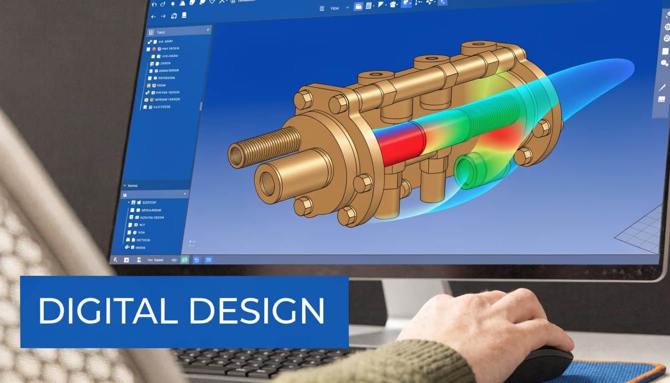
CAD Modelling and Flow Simulation Tips
Modern manifold block design lives or dies in CAD long before the machine shop sees a billet. A 3D model is not just a drawing output. It is where drilling logic, plug strategy, valve stacking, mounting detail, and service access are proved or exposed.
The most useful models are built to be changed. If a single passage move forces a complete rebuild of the model tree, the CAD method is too brittle for real project work.
Build the model around references that make sense
Whether the job is done in SolidWorks, Inventor, or another mainstream package, start with a fixed origin and consistent face references. That sounds basic, but it keeps valve cavities, ports, and drillings traceable when the design evolves.
Good modelling habits include:
- Use clear feature naming. "Cross drilling return A" is better than "Cut-Extrude47".
- Separate cavity features from connection drillings so revisions don't become a guessing game.
- Model plugs, fittings, and valve envelopes early because clashes usually appear there first.
- Keep service tooling in mind. If a hex plug cannot be reached with a standard tool, the digital model should reveal that before release.
Software can also automate parts of the process. Parametric manifold tools and add-ins are useful when they support the designer's judgement, but they don't replace it. Automated routing can still produce ugly, high-loss passage geometry if the functional layout is wrong.
Use flow simulation to challenge the drawing
A manifold can be geometrically correct and still behave poorly. That is where CFD and flow simulation earn their keep. They show where velocity spikes, abrupt direction changes, and constrictions are likely to create unnecessary pressure loss and heat.
The aim is not to create a beautiful colour plot for a design review. The aim is to answer practical questions:
- Is one branch starved because another route is too direct?
- Does a cavity outlet create a sharp expansion and recirculation zone?
- Is a pilot feed exposed to turbulence from a nearby high-flow passage?
- Can a drilling be enlarged or re-angled to make the route calmer and easier to machine?
Simulation is most useful when it changes a decision. If the model only confirms what was obvious already, it has been used too late or too lightly.
Later in the process, visual walkthroughs can help align design and production teams. This example video is the sort of reference many engineers use when discussing internal routing and 3D layout decisions:
Prepare the model for the workshop
The handover to CAM and machining is where avoidable confusion often starts. A model needs to tell the workshop what matters: critical bores, sealing surfaces, drill depths, thread forms, and which intersections must remain clean.
Before release, check these points:
-
Drilling sequence is logical
If the workshop has to guess which hole is machined first, the design package is incomplete. -
Closure strategy is obvious
Every cross-hole plug, seal, and unused machining feature should be intentional. -
Inspection features are identified
Critical faces and bores need clear tolerancing and a sensible inspection plan. -
Clean-out risk is understood
Long intersecting drillings, dead-leg pockets, and hidden burr traps should be flagged before machining starts.
An effective CAD process reduces drawing-room optimism. It exposes what can be machined, inspected, cleaned, and serviced.
Advanced Design Standards and Considerations
Some circuits do not fit in one block. Once the valve count rises, drilling paths become congested, or service access starts to disappear, a monolithic manifold can become harder to build and harder to maintain than a modular solution.
That isn't a compromise by default. In many applications, splitting functions across sub-blocks is the cleaner engineering answer.
When modular design makes more sense
A modular arrangement is often worth considering when the circuit combines high-flow power handling with several secondary control functions. Keeping those functions on separate blocks can simplify drilling, reduce plug congestion, and make future changes less painful.
Typical reasons to divide a manifold include:
- Different pressure duties across parts of the circuit
- Service access requirements for frequently replaced valves
- Machine packaging limits that make one large block awkward to mount
- Planned future variants where one module changes but the base module stays the same
The risk, of course, is that every interface between blocks adds sealing and assembly demands. If the mating faces, port alignment, and bolt loading are not treated properly, the modular concept can create the very leak paths a manifold was meant to remove.
Standards are not paperwork
CETOP and ISO interface standards save time only when they are used properly. A standard valve footprint gives interchangeability, but it doesn't rescue a poor internal layout. Likewise, specifying ports to recognised standards helps with fittings and maintenance, but the surrounding geometry still has to support sensible wrench access, sealing face quality, and hose orientation.
Practical design judgement is essential. A standards-compliant face can still be poor if the coil hits a bracket, the fitting fouls a guard, or the test port ends up inaccessible. Compliance is the baseline, not the finish line.
Standard interfaces reduce avoidable risk, but only if the whole installed assembly is considered at the same time.
Additive manufacturing and where it fits
For small-to-medium UK manufacturers, additive manufacturing (3D printing) offers a path to creating bespoke, low-volume manifold solutions by reducing tooling costs and lead times, though cost-benefit analysis is critical at specific production volumes, as discussed in this review of additive manufacturing for bespoke manifold applications.
The attraction is clear. Additive methods can create internal flow paths that would be difficult or impossible with conventional drilling. That opens the door to lighter forms, smoother transitions, and fewer compromises around inaccessible intersections.
But this is where judgement is needed. Questions that need answering before choosing additive manufacture include:
- What volume justifies it for the actual production run?
- What post-processing is required for sealing faces, threads, and valve cavities?
- How will the part be validated for hydraulic duty and repeatability?
- What does the customer expect in terms of serviceability and replacement lead time?
For many UK projects, additive manufacturing is strongest in prototyping, highly complex low-volume parts, and concept validation. Traditional machining still makes more sense for a large share of production manifolds because it is familiar, inspectable, and well supported by existing workshop capability.
Design choices that hold up over time
Advanced manifold work usually succeeds when complexity is controlled, not celebrated. The smartest-looking internal route is not always the best one. A modular assembly with straightforward sealing and clear function separation will often outlast a single-block design that was pushed too far.
That matters most on equipment that has to be repaired quickly. If a service engineer can isolate a sub-block, replace a valve, and get the machine running again without dismantling half the system, the design has done its job.
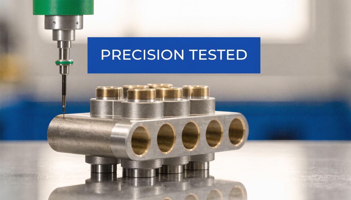
Machining Tolerances and Validation Testing
A manifold can be excellent in CAD and disappointing on the bench. The reason is usually not one dramatic fault. It is a chain of small manufacturing problems such as drift on a deep drilling, a poor sealing face, a burr left at an intersection, or a cavity machined to the edge of tolerance.
This stage is where design discipline has to meet workshop discipline. If those two teams are not aligned, defects appear late and expensively.
What to watch during machining
Valve cavities and sealing faces need consistent tolerance control because they decide whether the assembled block behaves predictably. Deep and intersecting drillings also deserve close attention. If the process relies on long unsupported drilling without a sound plan for chip evacuation and verification, contamination and blockage become much more likely.
A capable workshop will usually control manifold production through a defined process sheet rather than by drawing alone. That is one reason many firms now rely on dedicated project management software for machine shops to track machining stages, inspection holds, and release status across complex manufactured parts.
Practical checks during manufacture include:
- Critical cavity verification before the rest of the block is completed
- Plug thread inspection so sealing issues don't appear at final assembly
- Deburring of every intersecting passage rather than assuming flushing will remove everything
- Traceable inspection records for bores, faces, and key port locations
Cleanliness is not a finishing detail
Internal cleanliness affects the whole hydraulic system. A tiny burr or trapped chip can jam a cartridge valve, damage a seal, or create an intermittent fault that is hard to diagnose later.
That is why post-machining cleaning needs to be planned, not improvised. Flushing, air blow-through, visual checks, and where needed borescope inspection all have a role. If there is any doubt about whether a dead-end drilling is clean, there is already a problem.
For pressure verification in the workshop or during system commissioning, engineers often use dedicated hydraulic pressure tester kit equipment so the block can be checked safely and consistently.
Pressure testing and functional proving
A critical validation step is the hydrostatic test, where the completed manifold is pressurised to 1.5 times its maximum working pressure, such as 525 bar for a 350 bar system, to confirm its structural integrity before installation, as described in this guide to hydraulic manifold validation basics.
That test should not be treated as a box-ticking exercise. It is there to confirm that the block, plugs, interfaces, and machined structure hold pressure safely before the manifold goes anywhere near a machine.
If a manifold only gets its first serious pressure test after installation, the process has already failed.
Functional testing matters just as much. Pressure holding, directional operation, relief response, and any sequence or pilot functions should be checked against the original design intent. The block has to do more than survive pressure. It has to operate correctly, repeatedly, and without hidden restrictions.
Your Partner in Bespoke Hydraulic Design
Good manifold block design is methodical. The circuit has to be defined properly. The valve layout has to respect the oil path. The material has to suit pressure, environment, and duty. The CAD model has to support change, not fight it. The finished block then has to be machined cleanly, inspected properly, and tested with discipline.
That process is what prevents expensive mistakes. It avoids pressure-loss problems that only appear under load. It avoids service headaches caused by inaccessible valves and plugs. It avoids the false economy of choosing a material or layout that looks fine on paper but does not survive real industrial or mobile use.
When a bespoke manifold is done well, the result is not just a neater hydraulic assembly. It is a system that is easier to build, easier to maintain, and more predictable in service. That is why the best projects give equal weight to hydraulic performance, manufacturability, and long-term maintenance.
If you need support with manifold block design, bespoke hydraulic assemblies, or component selection for industrial and mobile applications, speak to MA Hydraulics Ltd. Phone 01724 279508 today, or send us a message.
