
The usual advice is to choose a check valve that matches the pipe size and stops reverse flow. That isn't enough for a hydraulic circuit. A valve can fit the connection perfectly and still restrict the pump, close badly or use seals that aren't suitable for the oil. Treat 1 1 2 check valve as a search description, not an order-ready specification.
Why a 1 1/2 Check Valve Needs More Than a Size
A 1 1/2-inch nominal-bore non-return valve needs a proper engineering identity. Your purchase order should describe the connection standard, allowable pressure, required flow, acceptable pressure drop, cracking pressure, fluid specification, seal material and permitted mounting position. Without those details, you're asking the supplier to make assumptions about your circuit.
There's also an application ambiguity. In hydraulic procurement, the phrase usually points towards a nominal connection size. In UK water-safety work, a loosely written “1 1 2” description can instead lead buyers towards two-check backflow protection, including RPZ assemblies. These aren't interchangeable interpretations.
Separate hydraulic duty from drinking-water protection
UK plumbing selection depends on the fluid category and contamination risk, not on the presence of a non-return mechanism. Single-check and double-check devices provide different protection arrangements, and anti-pollution check valves are associated with BS EN 13959, as outlined in BES guidance on check-valve selection.
RPZ acceptance is more specific still. Water Regulations UK's RPZ guidance specifies differentials greater than 0.34 bar (34 kPa) for the first check and 0.07 bar (7 kPa) for the second, with the latter potentially reduced to greater than 0.005 bar (0.5 kPa) where the check conforms to BS EN 13959:2004; it also states a relief-valve discharge criterion involving an upstream-to-intermediate differential exceeding 0.14 bar (14 kPa). Those are potable-water assembly criteria, not hydraulic cracking-pressure targets.
Procurement rule: Establish what the valve protects before discussing which connection fits.
The distinction between port size and performance is illustrated below.
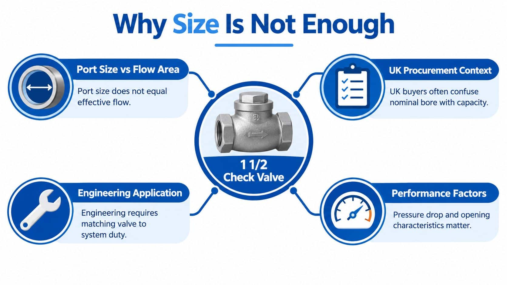
For hydraulic enquiries, send the circuit drawing and the existing valve identification alongside photographs. Include the function you need, such as preventing return flow or retaining pressure in an isolated branch. A photograph helps identify the hardware, but it doesn't establish the internal spring specification or the condition of the seat.
How Spring, Pilot and Poppet Check Valves Work
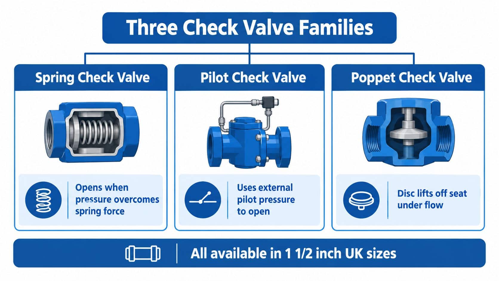
Don't treat spring, pilot and poppet as mutually exclusive descriptions. A spring-loaded valve can use a poppet, and a pilot-operated check can also contain a seated poppet. One term describes the closing force, another describes the release mechanism, and another describes the moving sealing element.
The diagram provides a useful starting vocabulary, but the manufacturer's sectional drawing and hydraulic symbol should settle the identification.
Spring-loaded and seated designs
In a spring-loaded check, forward pressure acts on the sealing element against the spring force. Cracking pressure is the upstream-to-downstream differential at which that element begins to lift from its seat. It isn't the pressure drop through the valve at full operating flow.
A poppet is a guided disc or shaped seated element. Forward flow lifts it; the closing arrangement returns it towards the seat when the opening force falls away. On a cylinder return branch, my recommendation is to check the whole return-path resistance before selecting the spring, rather than assuming a stronger spring gives better protection.
A swing check uses a hinged disc instead of a guided lifting element. For a low-pressure return line, it may be an option where the manufacturer permits the mounting position and the closure behaviour suits the circuit. Don't substitute it for a hydraulic cartridge merely because both devices prevent reverse flow.
Pilot-operated release
A pilot-operated check admits flow in its normal permitted direction and uses a separate pilot signal to release the otherwise blocked path. That adds a control requirement: the circuit must supply the necessary pilot pressure under the actual load and back-pressure conditions.
For a vertical cylinder, evaluate the complete load-control arrangement rather than assuming a pilot check alone provides controlled lowering. Use the pilot-operated check-valve range to discuss the required function, pilot connection and release conditions against the circuit drawing.
- Identify the ports: Separate the main flow connections from the pilot connection.
- Read the symbol: Confirm which path is free-flowing and which requires release.
- Request the section drawing: Body shape alone won't reveal the spring or seating arrangement.
For readers crossing over from plumbing, Good Boy Plumbing's guide to backflow prevention offers a separate water-system reference. Keep that context distinct from hydraulic load holding and component selection.
Comparing 1 1/2 Check Valve Types Side by Side
Choose the function first, then compare candidate products. A pilot-operated check isn't automatically an upgrade over a simple spring-loaded valve, and a standard poppet isn't automatically the cheapest option. Those conclusions require actual product data and quotations.
The useful comparison is whether each candidate meets the same duty. Don't accept a catalogue description as a substitute for an opening characteristic, installation instruction or service procedure.
Comparison of 1 1/2-inch check valve types
| Criterion | Spring-loaded | Pilot-operated | Standard poppet |
|---|---|---|---|
| Cracking pressure | Request the specified spring option and opening data | Check forward cracking pressure and pilot-release requirements | Confirm the closing arrangement and opening differential |
| Vertical or horizontal installation | Follow the approved mounting positions | Verify valve and pilot-port orientation requirements | Confirm whether closure depends on gravity or a spring |
| Resistance to chatter | Assess stability across the operating flow range | Assess both main-flow stability and pilot-signal behaviour | Review guide, seat and closure characteristics |
| Contaminated fluid | Obtain cleanliness requirements | Obtain requirements for main and pilot passages | Check seat sensitivity and permitted fluid condition |
| Pressure class | Use the selected model’s pressure-temperature data | Verify all main and pilot port limits | Use the selected model’s documented rating |
| Maintenance access | Check cartridge removal and spring availability | Allow access to pilot connections and service parts | Establish whether the seat and guided element are serviceable |
| Procurement priority | Straightforward non-return duty | Deliberate release of a blocked flow path | Suitable seated construction for the required duty |
For an ordinary non-return function, I'd start with a straightforward spring-loaded candidate and assess its operating data. If the circuit needs a separately commanded release, investigate a pilot-operated design. If a supplier proposes a standard poppet, ask what distinguishes it from the spring-loaded candidate rather than comparing labels.
Buy the operating characteristic you need, not the most elaborate mechanism on the quotation.
Keep comparisons within the right application
Vorsprung Autowerk's Vorsprung Autowerk check valve advice is an automotive vacuum-system reference, not a hydraulic pressure-rating authority. Use application-specific material for context, but don't transfer its component recommendations into an oil-hydraulic circuit.
During quoting, add a final column to your own comparison sheet for evidence received. A supplier's answer should point to a drawing, data sheet or written application confirmation. An unanswered criterion is a procurement action, not permission to assume the valve will work.
Sizing a 1 1/2 Check Valve for Real Flow and Pressure
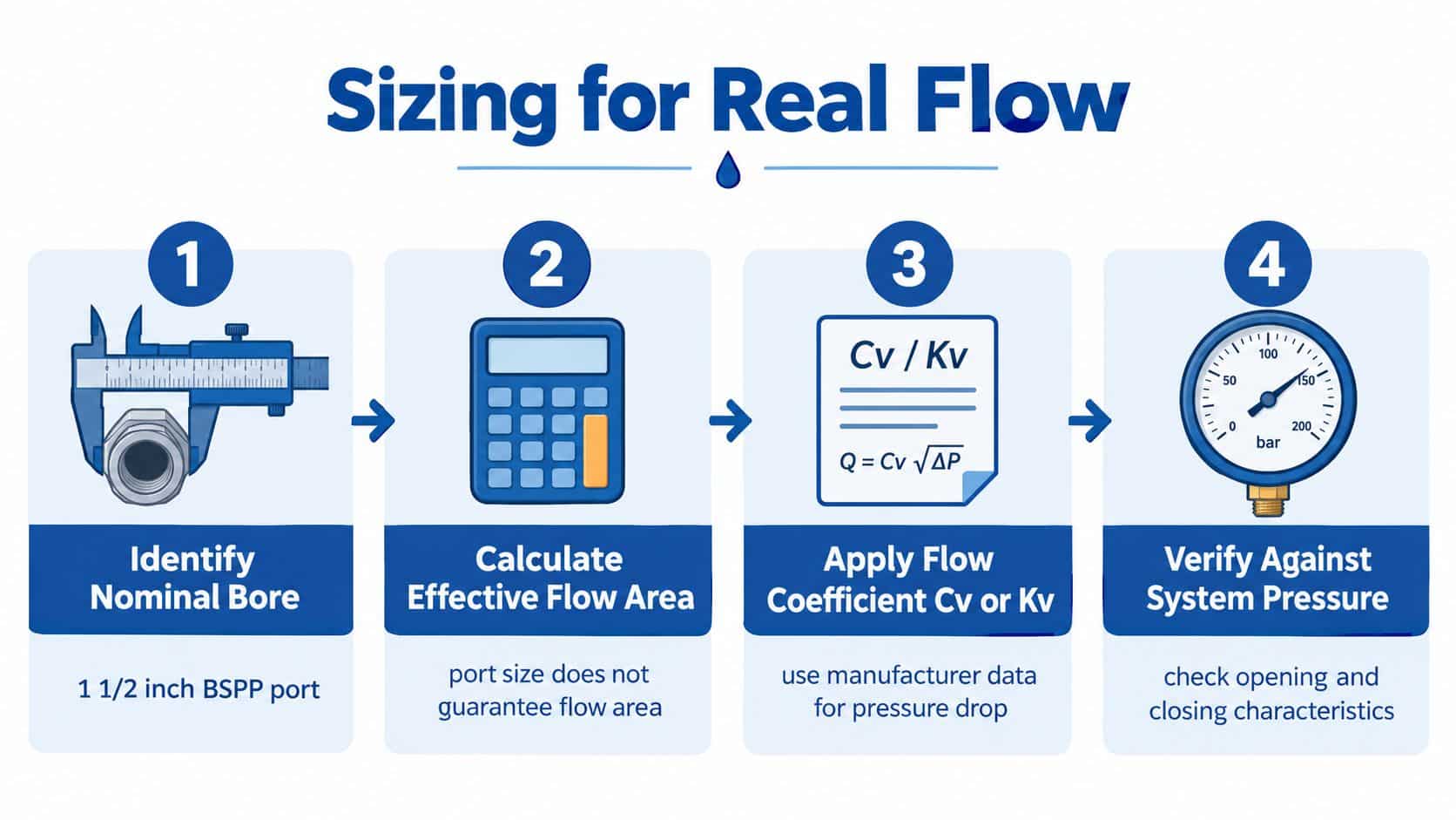
Size the valve around the flow it must pass and the pressure loss the circuit can tolerate. A nominal BSPP port designation doesn't tell you the effective opening through the seat. Request the manufacturer's pressure-drop curve, together with the fluid and temperature conditions used to produce it.
The sizing sequence below keeps the connection check separate from the hydraulic calculation.
Work from the operating conditions
Record flow in litres per minute, pressure in bar and operating temperature in °C. Include the oil specification and viscosity conditions, particularly where cold starting differs substantially from normal operation. Then use the manufacturer's curve or approved calculation method to establish the expected valve loss.
Cv or Kv can support a calculation, but only when you understand the coefficient's reference conditions and required fluid corrections. Don't use a water-based figure as an unqualified prediction for hydraulic oil. The flow-rate calculations resource is a useful companion when preparing the circuit information for selection.
Consider two explicitly hypothetical enquiries:
- A 60 L/min return line: Locate that duty on the selected valve's oil-flow curve, read the corresponding differential and add it to the other return-path losses. Reject the candidate if the complete return arrangement exceeds the allowable back-pressure.
- A 20 L/min pilot-controlled branch: Establish whether that flow belongs to the main controlled passage or the pilot supply. Size the relevant passage from its own data and separately verify that the pilot signal can release the valve.
Neither example produces a defensible pressure-drop answer without a real valve curve. Filling the gap with an assumed coefficient only makes the quotation look more complete.
Check connections and extremes
Confirm whether the nominal connection means BSPP, BSPT, NPT, SAE flange or DIN flange. Check the mating geometry rather than relying on the apparent diameter. Also verify performance at minimum flow, peak flow and pump shutdown, not just the normal running point.
The UK designated pressure-equipment standards list includes EN 16767:2020 for metallic industrial check valves and EN 12266-1 for valve pressure testing. Use these as relevant design and testing references, while demanding the selected product's own performance evidence.
On a suction-side application, my preference is to challenge whether a check valve is needed at all before accepting additional opening resistance. If it is necessary, confirm the available inlet-pressure margin with the pump supplier.
Pressure Ratings, Flow Capacity and UK Compliance
A pressure rating is a limit under stated conditions, not a promise of suitability everywhere. Ask for the valve's pressure-temperature envelope, body and seal materials, and the limits applicable to each connection. The weakest relevant limit governs the assembly.
For flanged products, compare flange drilling, facing and sealing arrangement against the mating equipment. A pressure-class label won't resolve a mismatch in bolt pattern or seal face. For threaded products, confirm both the thread form and the intended sealing method.
Request the compliance pack with the order
The GB pressure-equipment notice and designated standards provide the relevant conformity context: pressure-equipment requirements can apply where maximum allowable pressure is above 0.5 bar, and UKCA or CE marking requirements depend on the equipment's classification and applicable route. Don't apply a blanket marking rule to every valve.
Ask the supplier for:
- Manufacturer identification: A traceable model, part reference and production identification where provided.
- Applicable documentation: The declaration and conformity information required for that product.
- English instructions: Installation, operation and maintenance information that your service team can use.
- Operating limits: Allowable pressure, temperature, fluid compatibility and any application restrictions.
Check the documentation against the delivered component before releasing it to stores. A declaration for a similar-looking range isn't enough if the actual model or configuration differs.
Acceptance point: Compliance paperwork and hydraulic suitability are separate checks. Complete both.
I wouldn't pay for a higher pressure rating as a substitute for the right operating characteristic. It won't resolve an unsuitable spring, unstable closure or incompatible seal compound. Buy sufficient pressure capability for the duty, then judge service suitability from the complete specification.
Installation Orientation and Correct Flow Direction
Read the flow arrow before offering the valve up to the pipework. It identifies the intended permitted flow direction, not the direction that happens to suit the available space. Confirm the arrow against the circuit drawing and the manufacturer's port identification.
The photograph illustrates the marking to look for, not approval of that pictured valve for your hydraulic duty.
A fitting checklist worth keeping
Use the inline-valve installation guidance alongside the component instructions. Don't assume a spring-loaded design permits every orientation, or that a swing design can be rotated freely. Follow the specific mounting restrictions.
- Confirm the ports: Mark the intended upstream, downstream and pilot connections before assembly.
- Clean the interfaces: Protect open ports and inspect the sealing surfaces before fitting.
- Align and support the pipework: Don't pull misaligned pipes together through the valve body.
- Use the specified seals: Match washers, O-rings and other sealing components to the connection and fluid.
- Apply documented torque: Use the manufacturer's tightening values and sequence, not a generic setting based on nominal size.
- Preserve service access: Allow room for inspection, connection tools and safe removal.
Position the component in accordance with the manufacturer's instructions on debris management and accessibility. Don't improvise a mounting angle to solve a suspected contamination problem.
Keep visual instructions usable
Use the embedded demonstration only alongside the written port and direction checks.
Before relying on a workshop video, check that the frame shows the complete valve and its labels on both desktop and mobile screens. Suffolk County Council's accessibility guidance recommends descriptive iframe titles, captions and audio description where essential visual information isn't explained aloud.
Verify image wording against the component documentation. Check technical names in captions and provide an accompanying HTML transcript, following UK Government communications accessibility standards.
Commissioning and Functional Testing on Site
Commission the valve against an agreed test procedure, not by starting the machine and listening for trouble. Establish the test boundaries, authorised pressure, guarding, instrumentation and acceptance criteria before introducing pressure. Everyone involved should know how the circuit will be isolated and discharged.
HSE's pressure-testing guidance recommends beginning at low pressure below safe operating limits to establish initial integrity before increasing pressure. It also explains that conventional hydraulic-oil systems are generally outside the Pressure Systems Safety Regulations 2000, but that distinction doesn't remove the need for risk assessment and safe working.
Prove containment and operation
Start with an initial integrity check under controlled conditions. Inspect for external leakage using the approved safe method, keeping personnel clear of potential fluid release. If the initial check fails, stop and depressurise before investigating.
Once integrity is established, proceed through the authorised functional checks:
- Forward opening: Measure the differential at initial opening and compare it with the specified characteristic.
- Operating flow: Check the pressure loss at the agreed duty and watch for unstable behaviour.
- Reverse shut-off: Apply the approved reverse-flow test conditions and assess leakage against the stated acceptance criterion.
- Shutdown response: Observe the authorised operating sequence for chatter or an unacceptable closure event.
Don't exceed a component limit while trying to prove the rest of the system. The test pressure and method need to suit the entire test boundary.
Leave a usable commissioning record
Record installed direction, port standard, pressure rating, cracking pressure, seal compound, test medium and results. Add the valve reference, circuit location, instrumentation identification and any operating restrictions discovered during testing. Keep the record with the machine documentation rather than only in a technician's notebook.
Isolation must not leave pressure trapped between the check valve and another closed device. Provide and use a safe depressurisation route before loosening fittings or removing the component. Verify the isolated section is discharged by the approved procedure, rather than assuming a stopped pump means an unpressurised circuit.
A failed functional check requires investigation even when the body remains dry. Don't release the machine until the valve performs the required circuit function.
Maintenance, Failure Modes and When to Replace
Inspect the valve as part of the circuit, not as an isolated metal body. Chatter, reverse leakage and an abrupt shutdown response call for different investigations. Replacing the component without identifying the operating cause can leave the next valve exposed to the same conditions.
The distinction between containment and protection matters. SAFed and PECF guidance on pressure-equipment interpretation distinguishes a proof test from demonstration of an intended protective function. A valve that contains pressure hasn't necessarily proved satisfactory opening, sealing or closure behaviour.
Diagnose before ordering another valve
| Inspection finding | Investigation priority | Service decision |
|---|---|---|
| Chatter at partial flow | Compare operating flow with the selected valve’s stability data | Correct selection or circuit conditions before like-for-like replacement |
| Reverse leakage | Inspect for contamination, seat damage and worn sealing elements | Clean, repair or replace under the manufacturer’s procedure |
| Changed opening behaviour | Check the spring, guided movement and fluid condition | Verify the specified opening characteristic after intervention |
| External leakage | Examine connection seals, alignment and body condition | Correct the identified defect and repeat the relevant tests |
| Harsh closure at shutdown | Review transient behaviour and the closure mechanism | Assess a controlled-closure alternative against the complete circuit |
These are investigation routes, not diagnoses made from sound alone. For example, don't call every unstable noise “spring fatigue”. Inspect the available evidence, compare it with the commissioning baseline and check whether the machine's duty has changed.
Replace on function and condition
During authorised disassembly, inspect for seat erosion, damaged guides, spring deterioration and degraded elastomers. Investigate contamination or suspected water in the oil rather than treating the valve as the sole problem. Use approved replacement parts and the manufacturer's service limits.
After repair, repeat the relevant functional checks, not just an external leak inspection. If partial-flow instability or shutdown shock recurs despite correct installation and verified circuit conditions, ask the supplier to assess a non-slam or damped design. Don't select one solely from its name.
Retain a serviceable valve when it meets the documented acceptance criteria. Replace it when its condition, performance or supportability no longer meets the duty, and update the maintenance record so the next engineer knows why the decision was made.
MA Hydraulics Ltd supplies hydraulic check valves and offers component-selection support for replacement parts and new circuits. Send the team your valve identification, connection details, flow requirements and operating conditions so they can help assess a suitable 1 1/2-inch option. Phone 01724 279508 today, or send us a message.
