A hydraulic line rarely fails because of one dramatic event. More often, it starts with a small movement that nobody takes seriously. A steel tube chatters against a bracket. A return line picks up vibration from a gear pump. A support point loosens slightly after servicing, then the pipe begins to fret, oval, or mark. Weeks later, somebody finds dampness around a fitting, or a machine is down because a line has split where it should have stayed stable.
That’s where u bolt clamps earn their keep. They look simple, and that’s exactly why they’re often underspecified. In practice, they sit right at the intersection of restraint, movement control, corrosion resistance, and installation discipline. Choose the wrong one, and you can create the very problem you meant to prevent. Choose the right one, size it properly, and install it with some care, and it becomes one of the most dependable parts in the whole hydraulic assembly.
An Introduction to U Bolt Clamps Beyond the Basics
In UK hydraulics, u bolt clamps are not general hardware. They’re working components used to hold pipework and tubing in place while the system deals with pressure pulses, thermal change, machine movement, and vibration. That applies whether you’re looking at an agricultural power pack, a materials handling machine, or fixed plant in a manufacturing building.
The scale of use tells you these clamps are far from niche. Europe, including the UK, holds a 28% share of the global u-bolt clamps market, valued at USD 2.77 billion in 2024, according to Credence Research on the U-bolt clamps market. That matters because it reflects how widely these parts are used across automotive production, industrial infrastructure, and the hydraulic applications common in UK industry.
A design engineer usually notices u bolt clamps when something has already gone wrong. An MRO team notices them during a shutdown, when one support point shows rust bleed, a polished wear mark, or a nut that has backed off. The mistake is treating the clamp as if it only “holds the pipe up”. In a dynamic hydraulic system, it also influences fatigue life, alignment, serviceability, and how much stress ends up at the fittings.
Practical rule: If a pipe support is close to a pump, valve block, manifold, or machine frame that sees repeated movement, the clamp choice is part of the hydraulic design, not an afterthought.
That’s why it pays to buy from suppliers who understand the difference between a commodity fastener and a support component. If you’re comparing options, a broad selection of quality fasteners can be useful as a reference point, but the final choice still needs to match the pipe OD, support duty, environment, and expected vibration.
The Anatomy of an Industrial U Bolt Clamp
A proper industrial u bolt clamp has very little in common with the light-duty items sold for general site fixing. The shape may be similar, but the function is more demanding. In hydraulics, every part of the clamp contributes to how well it controls load without damaging the pipe.
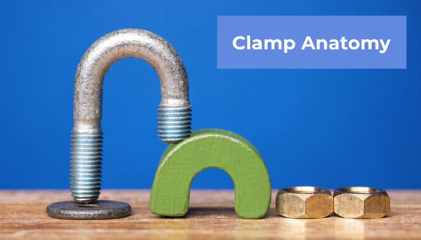
The bend, legs and threads
Start with the U-shaped bend. That curved section cradles the pipe and determines how the clamping force is introduced. If the bend radius is wrong for the pipe OD, the load won’t distribute properly. You end up with concentrated pressure points instead of stable support.
The legs matter just as much. They provide the clamping length and need enough straight, usable thread to pass through the mounting arrangement with proper nut engagement. On a real machine, poor leg length causes all sorts of site bodges, including washers stacked to make up space or nuts left with marginal thread contact.
Then there are the threads. On a decent industrial clamp, they should be consistent, cleanly formed, and suited to the intended nut and material pairing. Rough threads, poor plating, or mixed-quality nuts are an easy route to galling, uneven tightening, and false confidence during installation.
The saddle and nuts
Many hydraulic applications use a saddle or clamp plate with the u bolt. That part spreads load and helps keep the pipe seated correctly. Without it, you can still restrain the pipe, but you often lose control over pressure distribution and alignment.
The nuts are not a trivial detail either. They create and hold the clamp load. If they bind, strip, or loosen under vibration, the whole support point becomes unreliable.
A simple way to read an industrial specification is to break it into these core terms:
- Inside diameter identifies the internal width that must match the pipe outside diameter.
- Leg length tells you whether the clamp can pass through the mounting arrangement with full nut engagement.
- Thread size determines the mechanical interface and strongly affects achievable clamp load.
- Material grade tells you whether the clamp is suited to dry indoor service, wet plant, coastal exposure, or chemical splash.
A u bolt clamp is a small assembly, not a single bent rod. If one part is wrong, the whole support point is compromised.
What separates industrial grade from general purpose
The difference usually comes down to three things.
| Feature | Industrial u bolt clamp | General-purpose item |
|---|---|---|
| Material control | Specified material and finish | Often unspecified or loosely described |
| Thread quality | Consistent engagement and torque response | Variable fit and surface quality |
| Dimensional tolerance | Built around pipe support duty | Often adequate only for light restraint |
That’s why experienced engineers read the data sheet first and the catalogue title second.
Selecting U Bolt Clamp Materials and Coatings
A clamp that survives five years on an indoor power unit can fail within one winter on a tipper trailer or slurry pump set. Same nominal size, same drawing note, completely different duty. Material selection has to start with the actual service conditions, especially on UK hydraulic equipment that sees vibration, road salt, washdown, and long wet periods.
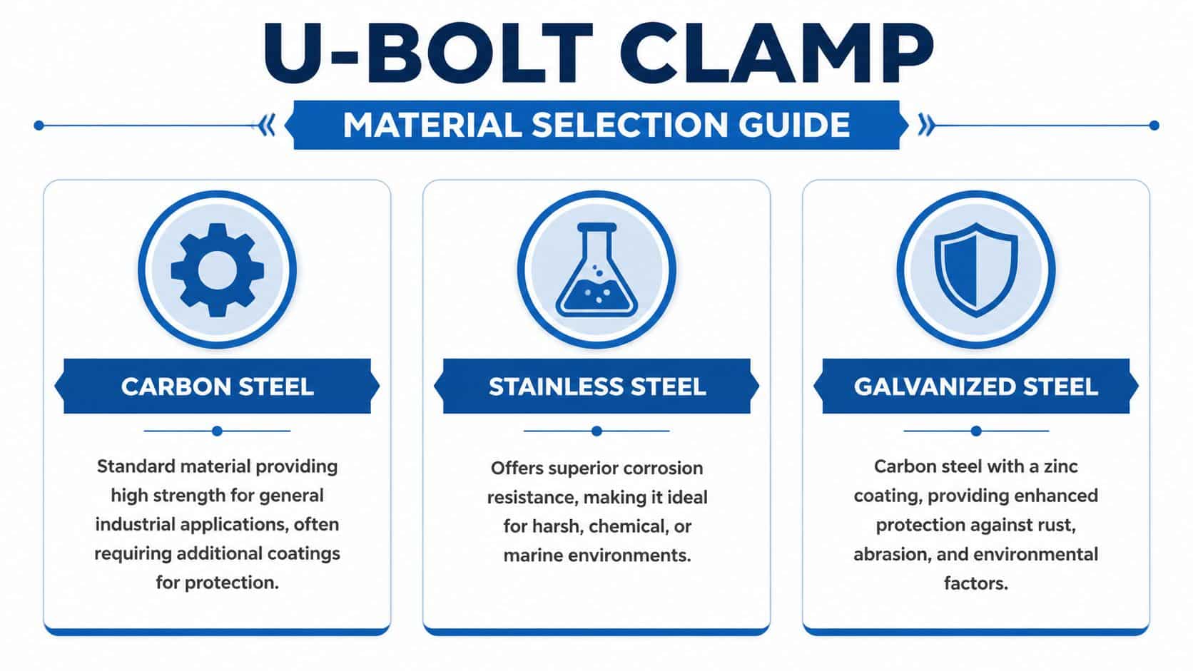
Carbon steel, stainless steel and galvanised options
Carbon steel is usually the starting point because it is strong, available, and cost-effective. It suits sheltered plant rooms, fixed machinery indoors, and support points that can be inspected easily. The limitation is corrosion margin. Once the finish is damaged by spanner marks, pipe movement, or grit trapped between the clamp and tube, plain carbon steel deteriorates quickly in damp service.
Stainless steel earns its keep where moisture is routine rather than occasional. That includes washdown areas, agricultural equipment, coastal sites, food production, and mobile plant exposed to winter roads. It also helps where maintenance access is poor, because the fasteners are less likely to seize solid by the time the clamp needs adjustment or replacement. Grade selection still matters. In chloride-rich environments, the wrong stainless grade can pit long before the rest of the assembly shows obvious damage.
Galvanised steel sits between the two on both cost and durability. It is often a sound choice for outdoor static equipment, general industrial yards, and exposed hydraulic pipework where stainless is hard to justify across the whole machine. The coating gives useful protection, but once it is worn through at the bearing points, corrosion starts locally and then spreads under the finish.
Material strength is only part of the decision. In dynamic hydraulic systems, surface behaviour matters as well. A clamp that is strong enough on paper can still shorten tube life if the material and finish promote fretting, trap moisture, or create local point loading as the line vibrates.
Coatings affect fatigue life, service life and maintenance effort
Coatings are often treated as a corrosion note for procurement. On working hydraulic equipment, they influence how the clamp behaves over time.
A thin plated finish may be acceptable on a dry indoor manifold stand. It is a poor choice for a vibrating pipe run under a vehicle body where grit, water, and salt are thrown at the threads every day. Hot-dip galvanising gives better outdoor protection, but the thicker coating can affect thread fit and nut running if the product is poorly made. Sherardised finishes are worth considering where you want more even zinc coverage without the heavier build-up associated with hot-dip galvanising. PTFE-coated variants can help in applications where reduced surface friction and extra chemical resistance are useful, but they are not a cure for poor clamp geometry or bad installation practice.
The practical question is simple. What happens after the coating is scratched, compressed, or rubbed by small cyclic movement? If the answer is red rust within months, the support point is under-specified.
Match the material to the environment and the failure mode
UK conditions push supports harder than many catalogue examples suggest. Outdoor mobile hydraulics see standing water, fertiliser, road salt, and repeated shock input. Coastal fixed plant adds salt-laden air. Indoor systems are easier, but even there, coolant mist, chemical cleaning, and occasional fluid leaks can attack finishes faster than buyers expect.
I usually separate the decision into two checks:
- What will attack the clamp from the outside? Water, chlorides, chemicals, washdown, mud, UV exposure, and trapped debris.
- What will load the clamp mechanically? Vibration, pressure pulsation, thermal movement, shock loading, and the risk of pipe fretting at the contact points.
That second point gets missed. On a dynamic line, corrosion resistance alone is not enough. If the clamp is rigid, the tube unsupported over too great a span, and the system sees pump ripple or chassis input, the pipe can fret against the clamp or crack next to it. Material choice needs to support the whole restraint strategy, not just survive the weather.
Composite and non-metallic options need careful judgement
There are cases where metallic clamps are not the best answer. Unistrut’s non-metallic U-bolt product guidance highlights composite options for corrosive environments. That can be useful context, especially where chemical exposure is severe.
For hydraulic service in the UK, I would still want clear answers on temperature range, long-term creep, clamp load retention, and behaviour under vibration before specifying them on a pressurised line support. Corrosion resistance is only one part of the job.
If you are reviewing surrounding restraint hardware as part of the same design decision, compare the service conditions across the full support package, including stainless steel worm clamps used for lighter-duty retention and shielding tasks.
What usually works in practice
| Environment | Usually sensible choice | What to watch |
|---|---|---|
| Dry indoor plant | Carbon steel with a suitable protective finish | Coating damage during installation and routine maintenance |
| Outdoor fixed equipment | Galvanised steel or stainless steel | Thread seizure, standing water, and neglected inspection intervals |
| Mobile hydraulics and agricultural duty | Stainless steel, or a coating system chosen for shock, dirt, and washdown exposure | Fretting, salt contamination, and fastener corrosion |
| Coastal or chemically aggressive service | Stainless steel with grade checked against the exposure, or an application-specific alternative | Pitting, crevice corrosion, and false confidence from generic catalogue notes |
The cheapest clamp is rarely the lowest-cost option over the machine life. On hydraulic systems that move, pulse, and live outdoors, the right material and finish reduce rework, protect the pipe, and keep the support point serviceable years after installation.
Sizing and Specifying to UK and International Standards
A clamp that fits the drawing but not the pipe will usually show up first on a live machine. The line starts to fret at the support, the nuts need retightening, and the fault gets blamed on vibration rather than poor specification. In UK hydraulic service, sizing needs to start with the actual pipe geometry, the expected load path, and the conditions the support will see through winter, washdown, and pressure cycling.
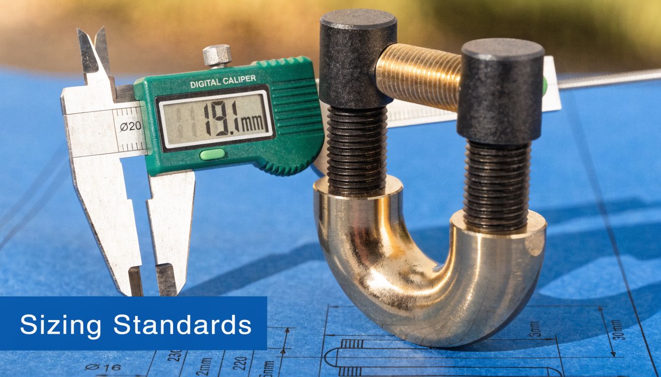
Specify from pipe OD, not nominal size
Nominal bore (NB) helps identify the pipe standard. Outside diameter (OD) decides whether the U-bolt fits and how it bears on the tube or pipe wall.
That distinction matters on hydraulic systems because support errors rarely stay local. An oversize clamp allows movement, impact, and wear at the contact point. An undersize clamp can flatten, mark, or preload the line before the system is even pressurised. On thin-wall tube, that is a reliability problem, not a paperwork issue.
For smaller line sizes and lighter retention duties, teams often cross-check stock support options against actual OD before ordering. If you are working around compact tube runs, 10 mm pipe clips for small-bore hydraulic lines are a useful comparison point because they show the same rule in practice. Size to the tube you have, not the label someone wrote on the work order.
A practical sizing method for dynamic hydraulic duty
Use the same sequence every time. It prevents the common purchasing and installation errors.
-
Measure the actual OD
Use calipers or the tube manufacturer’s specification. Painted pipe, plating build-up, and mixed standards can catch people out. -
Classify the support duty
Decide whether the clamp is carrying dead weight, controlling vibration, limiting lateral movement, or restraining a line near valves, pumps, or bends where dynamic loads are higher. -
Check clamp geometry, not just nominal size
Inside width, bend radius, thread size, leg length, and the bracket hole arrangement all need to suit the line and the support steel. -
Allow for movement and tolerances
Thermal change, pressure pulsation, frame flex, and hose-to-pipe transitions affect how the clamp sees load over time. -
Confirm the installation basis
If the design depends on a defined tightening method, write that into the job pack. A support point with controlled preload behaves differently from one tightened by feel. The T1A Auto torque wrench instructions are a straightforward reference for tool handling and repeatable torque application.
What standards mean in practice
In UK industrial work, BS 3974 Grip Type is a useful reference for form and fit. It gives a common basis for dimensions and installation intent, which helps when clamps are being sourced by different buyers or fitted by different maintenance teams across sites.
Internationally, the bigger issue is compatibility between pipe standards, material specifications, and supplier catalogues. A clamp listed against a nominal pipe size in one catalogue may not match the OD or thread expectation in another. That is where drawings need to be explicit. State the actual pipe OD, clamp material, finish, thread, leg length, washers, nuts, and any liner or isolation requirement. If the system is hydraulic and dynamic, include the service condition as well.
Dynamic systems need more than a fit check
Hydraulic lines do not load supports in a clean static way. Pressure ripple from pumps, valve switching, machine shock, and structural vibration all feed into the clamp. The support therefore needs enough restraint to control movement without creating a hard spot that shifts stress into the tube wall or the next fitting.
These are the sizing errors I see most often in service work:
| Mistake | Likely result in service |
|---|---|
| Selecting by NB only | Poor contact fit and movement at the support |
| Ignoring OD tolerance or coating thickness | Local marking, clamp looseness, or forced fit |
| Sizing for static weight only | Fatigue, fretting, and repeated retightening |
| Too little thread engagement or leg length | Insecure clamping and uneven load through the bracket |
| No allowance for UK outdoor exposure | Corroded threads, seized nuts, and loss of serviceability |
One point is often missed. A clamp near a pump skid or mobile hydraulic power pack may need a different specification from an identical clamp size elsewhere on the same machine. Same pipe. Different duty.
Write a specification that the workshop can use
A workable U-bolt clamp specification should let purchasing buy the right part and let maintenance confirm it is correct before fitting. At minimum, include:
- Pipe or tube actual OD
- Clamp inside width or grip size
- Thread size and leg length
- Material and coating
- Support bracket thickness and hole size
- Required nuts, washers, and any isolating sleeve or liner
- Service condition, especially if the line sees vibration, washdown, salt exposure, or outdoor temperature swings
If those details are missing, the workshop fills the gaps on site. That is where support problems start.
A properly specified U-bolt clamp does more than hold a pipe in place. It controls movement, protects the line from wear, and stays serviceable long enough for the rest of the hydraulic system to reach its maintenance interval without support-related failures.
Installation Best Practices and Torque Control
A clamp fitted on a calm workshop bench can look perfect. Put that same assembly on a UK hydraulic power pack beside a pump, in winter rain, with pressure pulsation and frame vibration, and poor installation shows up fast. The usual causes are uneven tightening, bad alignment, no torque control, or using the clamp to force a pipe run into place.
The right tightening sequence
Start with the line in its natural position. The bracket needs to sit square, the U-bolt legs need to pass cleanly through the support, and the pipe must already be where the design intended it to run. If a fitter has to bar the pipe across to meet the clamp, the support point is wrong or the run is carrying residual stress. That preload often turns into fretting, loosening, or fatigue once the machine is back in service.
Tighten the nuts evenly, alternating from side to side in small increments so the clamp comes down parallel to the support. Hand-seat the hardware first, confirm the pipe is still centred, then bring it up with a torque wrench to the specified value for the fastener, material, and lubrication condition. Dry stainless threads do not behave like zinc-plated carbon steel. A lubricated thread can generate much higher clamping force from the same torque, so workshop practice needs to match the specification.
For dynamic hydraulic systems, the target is controlled restraint, not maximum squeeze. Clamp load has to stop movement without crushing tube, marking softer pipe, or distorting thin-wall sections. That balance matters more near pumps, engines, valve manifolds, and mobile equipment where vibration input is constant.
Why torque control matters
Torque control is basic reliability work.
Under-tightening allows the pipe to shuffle in the support. You then get witness marks, coating wear, noise, and gradual nut back-off. Over-tightening brings a different set of problems: thread damage, local pipe flattening, bracket distortion, and higher stress at the U-bolt bend radius. In a hydraulic installation, either condition can shorten the life of the support and the line it is meant to protect.
Use a torque wrench and record the value where the job is safety-critical or hard to access later. If somebody in your team needs a basic refresher on technique, the T1A Auto torque wrench instructions are a useful reminder of correct wrench handling and setting practice. The principle carries over even though the application differs.
Smaller line supports follow the same discipline. This range of 10 mm pipe clips for hydraulic line support makes the same point. Fit, restraint, and material choice still matter even when the loads are lower.
A field checklist that works
On site, a simple routine prevents a lot of repeat visits:
- Seat the pipe before tightening so the clamp is retaining the line, not pulling it into alignment.
- Alternate between nuts to keep load even across the clamp and bracket.
- Check thread condition first especially on stainless hardware exposed to dirt, road salt, or washdown.
- Use suitable washers and nuts so load is spread properly into the bracket and the finish is not damaged during assembly.
- Watch the pipe profile for early signs of ovalling or surface marking as torque is applied.
- Re-torque after initial running on vibrating equipment, especially new installs where bedding-in can reduce clamp load.
Here’s the video reference before the next point. It’s a useful visual reminder that clamp tightening is a controlled process, not a brute-force exercise.
Avoiding distortion and loosening
Ovalling is one of the first installation faults to check for, particularly on thinner-wall tube, softer materials, or any line already carrying side load. Once the pipe loses its round section, contact pressure becomes uneven and the clamp stops sharing load properly around the circumference.
I treat that as a warning sign, not a cosmetic issue. If the pipe is marking during installation, the support arrangement needs checking before the machine runs. The answer may be lower assembly torque, a revised support spacing, an isolating liner, or a different clamp type altogether.
Good installers do one extra thing. They inspect the support again with the system running. If the pipe is moving, buzzing against the clamp, or transmitting pump vibration straight into the bracket, the job is not finished even if the nuts are at the specified torque.
Recognising Common Failures and Proactive Maintenance
Most failed u bolt clamps give you warning before they become a breakdown. The trouble is that the warning signs are easy to miss if nobody is looking specifically for them during inspection.
Corrosion is the obvious one. You see rust staining around the legs or nuts, white deposits on plated finishes, or local attack where moisture sits between clamp and pipe. In UK service, this often shows up first on outdoor machinery, washdown equipment, and any installation where road dirt or fertiliser residue stays trapped.
The failure modes worth knowing
Uniform corrosion is usually straightforward. The finish has degraded, the environment is harsher than expected, or the clamp was under-specified from the start.
Crevice corrosion is more subtle. It forms in the hidden contact area between the clamp and the pipe, especially where moisture and contamination sit undisturbed. The outside can look acceptable while the contact face is already compromised.
Fatigue cracking near the bend is common on dynamic systems. The pipe moves, the clamp sees repeated cyclic loading, and a crack starts at the highest-stress area. If the support point is close to a pump, engine, or moving frame section, pay attention there first.
Thread damage or galling usually points to poor material pairing, bad surface condition, contaminated threads, or over-tightening during installation.
What the symptoms usually mean
A quick diagnosis table helps in the field:
| Symptom | Likely cause | Typical response |
|---|---|---|
| Rust bleed at nuts or legs | Wrong material or finish for environment | Inspect, clean, and replace with better-suited material if needed |
| Polished wear mark on pipe | Clamp too loose or wrong size | Reassess fit and restraint |
| Flattening or marking of pipe | Over-tightening or poor saddle contact | Replace and correct installation method |
| Crack near bend radius | Vibration fatigue or incorrect sizing | Replace and review support arrangement |
| Seized or rough threads | Corrosion, galling, mixed materials | Replace hardware and review coating/material choice |
A clamp that has started rubbing the pipe is already telling you the support point has lost control.
What to check during routine maintenance
An MRO inspection doesn’t need to be complicated, but it does need to be deliberate.
- Look for movement marks where the pipe has polished, fretted, or worn against the clamp.
- Check nut security and signs of backing off after vibration.
- Inspect the contact area for trapped dirt, rust staining, or fluid residue.
- Assess the pipe shape and watch for local flattening.
- Review nearby components such as flexible hoses, manifolds, or pump mountings that may be feeding vibration into the line.
Where loosening is a recurring issue, controlled use of products like thread locking adhesive can support a broader fastening strategy, but it shouldn’t be used as a substitute for correct sizing, fit, and torque.
Replace early, not late
A u bolt clamp is inexpensive compared with the cost of a machine stoppage, fluid leak, or damaged pipe. Once a clamp shows cracking, severe corrosion, thread failure, or persistent movement marks, replacement is usually the sensible choice.
The point of maintenance isn’t just to keep the clamp serviceable. It’s to stop the clamp from becoming the reason the hydraulic line fails.
Sourcing the Right U Bolt Clamps for Your Application
The biggest mistake buyers make is treating u bolt clamps as catalogue commodities. They aren’t. Not in hydraulic service, not on vibrating mobile equipment, and not on plant where a failed support can lead to pipe damage and fluid loss.
A specialist supplier adds value before the clamp is even ordered. They’ll ask for the actual pipe OD, expected duty, support arrangement, material requirement, and whether the line needs rigid restraint or controlled movement. That short conversation often prevents the most expensive mistakes.
The verified data supports that approach clearly. According to NORMA Group’s U-bolt clamp product information, improper sizing can cause ovalling deformation in pipes under 300 bar pressures, leading to leaks costing UK manufacturers £500 to £2000 per incident. The same verified source also gives a practical load example of a 114 mm OD pipe clamp supporting 12 kN, which is exactly the sort of load-table detail engineers need when the application is more than a simple bracket job.
What a good supplier should help you confirm
A worthwhile supplier should be able to help with:
- Correct fit against actual OD, not rough nominal assumptions
- Material choice for dry indoor, outdoor, washdown, or corrosive service
- Thread and leg dimensions so the clamp suits the support steel
- Load table interpretation where the line sees dynamic service
- Availability for MRO work when breakdowns don’t wait for long lead times
That matters even more if the clamp is part of a wider hydraulic assembly involving manifolds, gear pumps, valve banks, or bespoke power pack pipework. Support hardware has to match the behaviour of the whole system.
The right clamp isn’t the one that merely fits the pipe. It’s the one that keeps the pipe stable for the life you expect from the machine.
A general distributor can sell a bent fastener. A proper hydraulic supplier should help you avoid an avoidable failure.
If you need help choosing the right u bolt clamps, support hardware, or related hydraulic components, speak to MA Hydraulics Ltd. The team can help with practical specification advice for OEM builds, repairs, and MRO work across mobile and industrial applications. Phone 01724 279508 today, or send us a message.
